Note: Descriptions are shown in the official language in which they were submitted.
CA 02776686 2012-04-03
WO 2011/046535
PCT/US2009/060346
LOAD SENSE HYDRAULIC PUMP ALIGNMENT
FIELD OF THE INVENTION
The present disclosure relates to forestry equipment. More particularly, the
present disclosure relates to a system for managing pumps used to power
hydraulic
units on forestry equipment.
BACKGROUND OF THE INVENTION
Forestry equipment is used to fell trees during harvesting. One type of
forestry equipment is a tracked harvester that includes a harvesting head the
grasps a
tree to be felled, downs the tree with a chain saw, and cuts the felled tree
trunks to
length with the chain saw. The hydraulic components of the harvesting head are
powered by one or more hydraulic pumps.
SUMMARY
According to one embodiment of the present invention, a tree harvester is
provided that includes a chassis; at least one ground engaging mechanism
configured
to propel the chassis over the ground; a harvesting head including a saw
configured to
cut trees; a plurality of hydraulic units including a hydraulic motor to power
the saw;
and a hydraulic control system. The hydraulic control system includes a first
hydraulic pump providing pressurized hydraulic fluid; a plurality of valves
controlling
the supply of hydraulic fluids from the first hydraulic pump to the plurality
of
hydraulic units; a load sense system that detects the load pressure
requirements of the
plurality of hydraulic units and provides instruction to the first hydraulic
pump to
produce pressure sufficient to satisfy the requirements of a highest of the
load
pressure requirements of the plurality of hydraulic units; and a second
hydraulic pump
providing hydraulic fluid to the harvesting head, the hydraulic motor
providing a load
sense signal to the load sense system to control operation of the first
hydraulic pump
BDDB01 5823932v1
CA 02776686 2012-04-03
WO 2011/046535
PCT/US2009/060346
and a load sense signal to the second hydraulic pump to control operation of
the
second hydraulic pump.
According to another aspect of the present invention, a method of harvesting
trees including the steps of providing a tree harvester including a chassis,
traction
devices configured to propel the chassis, a plurality of hydraulic units, a
harvester
head having a saw and hydraulic motor configured to power the saw, and a
hydraulic
system configured to operate the plurality of hydraulic units and the
hydraulic motor;
sensing the maximum load pressure required of the plurality of hydraulic units
and the
harvester head; controlling a first hydraulic pump based on the sensed maximum
load
pressure; sensing the load pressure required by the harvester head;
controlling a
second hydraulic pump based on the sensed load pressure required by the
harvester
head; combining the output of the first and second hydraulic pumps to power
the
harvester head; and harvesting a tree using the saw.
BRIEF DESCRIPTION OF THE DRAWINGS
The above-mentioned and other features and advantages of this disclosure, and
the manner of attaining them, will become more apparent and the disclosure
itself will
be better understood by reference to the following description of embodiments
of the
invention taken in conjunction with the accompanying drawings, wherein:
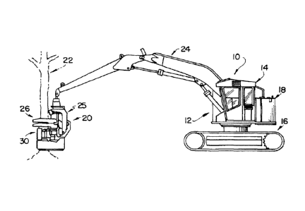
Figure lA is an elevational view of a tracked tree harvester showing the
harvester including a chassis, a pair of tracks propelling the chassis, a
boom, and a
harvesting head supported by the boom,
Figure 1B is an enlarged, front elevational view of the harvesting head of
Figure 1A;
Figure 2 is a schematic diagram illustrating an hydraulic system of the
tracked
harvester of Fig. 1,
Figure 3 is a schematic diagram illustrating an alternative embodiment
hydraulic system for use with the tracked harvester of Fig. 1,
2
BDDB01 5823932v1
CA 02776686 2016-01-08
Figure 4 is a schematic diagram illustrating another alternative embodiment
hydraulic system for use with the tracked harvester of Fig. 1, and
Figure 5 is a schematic diagram illustrating another alternative embodiment
hydraulic system for use with the tracked harvester of Fig. 1.
Corresponding reference characters indicate corresponding parts throughout the
several views. The exemplifications set out herein illustrate exemplary
embodiments of
the invention and such exemplifications are not to be construed as limiting
the scope of
the invention in any manner.
DETAILED DESCRIPTION
Referring to Fig. 1, a tracked tree harvester 10 of the present embodiment
illustratively includes a chassis 12 having a cab portion 14, a plurality of
tracks 16 for
supporting chassis 12 above the ground, an engine 18 for powering tracks 16 to
propel
chassis 12, and a harvesting head 20 for harvesting trees. Tracked harvester
10 also
includes a linkage assembly or boom 24 that allows harvesting head 20 to be
raised,
lowered, and tilted to position harvesting head 20 at a desired position
relative to a tree
22 to be felled. Although a tracked harvester is shown and described herein
using tracks
16 as propulsion devices, harvesting head 20 may be provided on other types of
tree
harvesters, such as wheeled tree harvesters that use tracks as propulsion
devices.
Additional details of harvesters are provided in U.S. Patent No. 4,412,569 and
U.S.
Patent Publication No. 2008/0289724.
As shown in Figs. lA and 1B, harvesting head 20 includes a support frame 25
supported by boom 24, arms 26, and chain saw 28 powered by a hydraulic motor
32.
Arms 26 grasp tree 22 while chain saw 28 cuts through tree 22. Harvesting head
20
further includes advancing wheels 30 that move cut tree 22 relative to head 20
to
position chain saw 28 at locations to cut tree 22 into segments. Once tree 22
is
segmented, arms 26 open to release the remaining portion of tree 22 still held
by head
20. Chain saw 28 and wheels 30 are powered by hydraulic motors, such as motor
32,
and arms 26 are powered by hydraulic cylinders (not shown). Additional details
of
3
CA 02776686 2016-01-08
suitable harvesting heads are provided in U.S. Patent Nos. 4,881,582;
6,516,841;
6,691,751; 6,962,178; and 7,296,602.
The hydraulic motors, such as motor 32, and hydraulic cylinders of harvesting
head 20 and the other hydraulic units 56 of tracked harvester 10 are powered
by a first
hydraulic pump 50 as part of a hydraulic system 52. Harvesting head 20 is also
powered by a second hydraulic pump 54 as part of hydraulic system 52.
Hydraulic
system 52 coordinates the supply of hydraulic fluid to harvesting head from
first pump
50 and second pump 54 based on the load pressure requirements of harvesting
head 20.
All of the hydraulic fluid of second hydraulic pump 54 is provided to
harvesting head
20. Whereas, the hydraulic fluid of first hydraulic pump 50 is split between
harvesting
head 20 and the other hydraulic components of tracked harvester 10.
Hydraulic system 52 is a load sense system that detects the highest pressure
required by hydraulic system 52 and controls pump 50 to provide an output
pressure
sufficient to satisfy this highest required pressure. Hydraulic system 52
receives the
load pressure requirement of each of a series of hydraulic units 56, such as a
hydraulic
cylinder used to power linkage assembly 24, and passes the highest pressure
through
main load sense line 57 to a pump control 58 for first pump 50. In response,
pump 50
provides hydraulic fluid at a pressure sufficient to satisfy the highest
pressure required.
Similarly, hydraulic system 52 includes a pump control 60 for second pump 54
that
controls the operation of second pump 54. Pump control 60 reacts to the load
requirements of harvesting head 20 to provide hydraulic fluid to harvesting
head 20
based on the needs of harvesting head 20.
Hydraulic system 52 further includes a series or stack of valve assemblies 61
that control the supply of hydraulic fluid to the respective hydraulic units
56. Each
valve assembly 60 includes a selection valve 62 that controls the flow of
fluid to a
hydraulic unit 56 and a pressure compensator 64 to compensate for the high
pressure
output of pump 50 resulting from the input of load sense system 53. When a
particular hydraulic unit 56 does not require the highest pressure provided by
first
pump 50, pressure compensator 62 reduces the supply pressure to the particular
hydraulic unit 56. Additional details of a suitable load sense system are
provided in
4
CA 02776686 2016-01-08
U.S. Patent No. 7,415,822, titled "Load Sense Boost Device," filed July 21,
2005, to
Harber et al. Although hydraulic units 56 are shown as hydraulic cylinders in
Fig. 2,
hydraulic units 56 may be other hydraulic units, such as hydraulic motors to
drive
tracks 16, and other hydraulically powered devices.
As shown in Fig. 2, one of the valve assemblies, valve assembly 61a, controls
the flow of hydraulic fluid from first pump 50 to harvesting head 20.
Hydraulic system
52 also includes a saw on/off valve 65 that controls the flow of fluid through
harvesting
head 20 to start and stop chain saw 28 rotating for example. On/off valve 65
controls
exhausting of hydraulic fluid from harvesting head 20 and the supply of
hydraulic fluid
from second pump 54. On/off valve 65 is a solenoid valve that receives an
electronic
signal to open when an operator decides to activate chain saw 28 by moving
switch 67
to an on position. When open, valve 65 allows hydraulic fluid to exhaust from
harvesting head 20 to tank 66. When closed, valve 65 blocks hydraulic fluid
from
exhausting to tank 66. As a result, no fluid flows through harvesting head 20
to rotate
the bar of chain saw 28. Therefore, valve assembly 61a and on/off valve 65
cooperate
to control harvesting head 20. Harvesting head 20 preferably includes one or
more
valves (not shown) that control the operation of the hydraulic features, such
as
retraction and extension of arms 26, rotation of the chain bar of chain saw
28, and the
other hydraulic features of head 20. According to an alternative embodiment of
the
present disclosure, the features of valve assembly 61a and on/off valve 65 may
be
combined in a single valve or other device or otherwise divided among multiple
valves
or other devices.
The demand of harvesting head 20 is communicated to pump control 58 for first
pump 50 and pump control 60 for second pump 54. As shown in Fig. 2, a pressure
sensor 68 is provided on harvesting head 20 to detect the load sense pressure
of
harvesting head 20. This load sense pressure is then used to control the
output of pumps
50, 54 to power harvesting head 20 and power rotation of the chain of chain
saw 28 and
the other hydraulic features of harvesting head 20.
As shown in Fig. 2, pressure sensor 68 is coupled to a proportional relief
valve
70 that controls exhausting of fluid from hydraulic line network 72 to control
the output
5
CA 02776686 2016-01-08
of pumps 50, 54. Network 72 includes a primary line 74. Primary line 74 is
coupled to
saw valve assembly 61a at valve port 76 that continuously provides hydraulic
fluid to
primary line 74 whether or not instructions are provided to power harvesting
head 20
and chain saw 28. When pressure sensor 68 detects no load or demand from
harvesting
head 20, it sends a low electrical current signal to proportional relief valve
70. In
response, proportional relief valve 70 allows the hydraulic fluid provided to
primary
line 74 by valve assembly 61a to exhaust to tank 66. As a result, little or no
pressure
builds up in primary line 74.
When pressure sensor 68 detects some load or demand from harvesting head 20,
it provides a higher electrical current to proportional relief valve 70. In
response,
proportional relief valve 70 restricts the flow of hydraulic fluid provided to
primary line
74 by valve assembly 61a from exhausting to tank 66. As a result, pressure
builds in
primary line 74. As pressure sensor 68 detects a greater load or demand from
harvesting
head 20, proportional relief valve 70 further restricts the flow of hydraulic
fluid to tank
66 and the pressure builds further. As pressure builds in primary line 74,
pressure also
builds at valve port 76 of valve assembly 61a. This pressure is fed into load
sense
system 53 of hydraulic system 52. If the load pressure of harvesting head 20
exceeds
the load pressure of the other hydraulic units 56, this pressure is passed
onto pump
control 58 to control the output pressure of pump 50 at a level sufficient to
satisfy the
demand of harvesting head 20.
On occasion, pump 50 may require more power from engine 18 than engine 18
can provide in a satisfactory manner, which will cause engine 18 to stall. To
avoid
engine stall when harvesting head 20 is demanding more pressure than engine
18,
through pump 50, can provide, network 72 includes a power feedback line 79
that
provides direct feedback to pump control 58 that limits the torque
requirements of
pump 50 to avoid engine stall.
Network 72 further includes secondary line 78 coupled to output line 80 from
second pump 54. Second pump 54 continuously provides hydraulic fluid at a load
sense
pressure to output line 80 whether or not instructions are provided to power
6
CA 02776686 2012-04-03
WO 2011/046535
PCT/US2009/060346
harvesting head 20 and chain saw 28. Secondary line 78 includes first branch
82 that
extends to proportional relief valve 70 and includes a check valve 84 blocking
back
flow of fluid from primary line 74. Secondary line 78 further includes a
second
branch 86 that extends to pump control 60 for second pump 54. As stated above,
when pressure sensor 68 detects no load or demand from harvesting head 20, it
sends
a low electrical current signal to proportional relief valve 70. In response,
proportional relief valve 70 allows the hydraulic fluid in first branch 82 of
secondary
line 78 to exhaust to tank 66. As a result, little or no pressure builds up in
second
branch 86 of secondary line 78 and little or no pressure is provided to pump
control
60 so that pump 54 does not increase its output pressure above the load sense
pressure
mentioned above.
When pressure sensor 68 detects some load or demand from harvesting head
20, it provides a higher electrical current to proportional relief valve 70.
In response,
proportional relief valve 70 restricts the flow of hydraulic fluid from first
branch 82 of
secondary line 78 to tank 66. As a result, pressure builds in secondary line
78,
including first and second branches 82, 86. As pressure sensor 68 detects a
greater
load or demand from harvesting head 20, proportional relief valve 70 further
restricts
the flow of hydraulic fluid to tank 66 from secondary line 78 and the pressure
builds
further. As pressure builds in second branch 86 of secondary line 78, pressure
also
builds at pump control 60 so that pump 54 increases its output pressure.
As pump 54 increases its output pressure, secondary line 78 communicates
this pressure to pump control 60 through second branch 82 resulting in even
greater
pressure output from pump 54. Eventually, pump 54 either reaches its maximum
output pressure or proportional relief valve 70 bleeds sufficiency pressure
from
secondary line 78 to maintain the output of pump 54 at the desired pressure as
determined by the output of pressure sensor 68.
To avoid rapid fluctuations in inputs to pump control 60, an orifice or flow
restriction 88 is placed in secondary line 78. During initial ramp up of the
output
pressure of pump 54, orifice 88 provides a pressure drop to dampen the
influence of
the change in output pressure from pump 54.
7
BDDB01 5823932v1
CA 02776686 2016-01-08
According to an alternative embodiment of the present disclosure shown in Fig.
3, proportional relief valve 70 for controlling pump 50 is replaced by a
piloted sequence
valve 90 and pressure sensor 68 for controlling pump 50 is replaced with a
hydraulic
line 92 extending from harvesting head 20 to piloted sequence valve 90.
Primary line 74
provides continuous load sense pressure to piloted sequence valve 90 and load
pressure
from harvesting head 20 controls exhausting of this pressure to tank 66. As
load
pressure from harvesting head 20 increases, less pressure is exhausted to tank
66, which
causes pressure in primary line 74 to increase. As discussed above, this
pressure is fed
into load sense system 53 of and potentially back to pump control 58 of pump
50 if the
load pressure of harvesting head 20 is greater than the other load inputs to
the load sense
system. A similar piloted sequence valve arrangement can be provided to
control the
input to pump control 60 of pump 54 when pressure sensor 68 is not provided.
As shown in Fig. 4, according to another alternative embodiment, proportional
relief valve 70 is provided to control second pump 54 as described above with
the
exception that a programmable logic controller (PLC) 94 is positioned between
load
sense pressure sensor 68 and proportional relief valve 70. Preferably, the
output from
PLC 94 to proportional relief valve 70 is proportional to the input to PLC 94
from
pressure sensor 68. As shown in Fig. 4, PLC 94 also provides input to pressure
relief
valve 96 to control exhausting of load sense pressure from valve assembly 61a
to tank
66. Thus, rather than one proportional relief valve 70 controlling the input
to pumps 50,
54, two pressure relief valves 70, 96 are used to control the respective pumps
54, 50.
With this configuration, pumps 54, 50 can be controlled independently through
the logic
of PLC 94. Power feedback line 79 provides feedback to pump control 58 that
limits the
torque requirements of pump 50 to avoid engine stall. An alternative power
feedback
line 79' may also be provided.
Another alternative embodiment control arrangement is provided in Fig. 5.
Compared to the embodiment of Fig. 4, valve assembly 61a is directly
controlled with
an electronic signal from PLC 94 and a supply pressure sensor 98 is provided.
The
output from PLC 94 to proportional relief valve 70 remains proportional to the
load
sense output from pressure sensor 68. The output from PLC 94 is proportional
to the
8
CA 02776686 2016-01-08
supply pressure provided by pressure sensor 98 less the load sense pressure
provided by
pressure sensor 68.
The scope of the claims should not be limited by particular embodiments set
forth herein, but should be construed in a manner consistent with the
specification as a
whole. This application is therefore intended to cover any variations, uses,
or
adaptations of the disclosure using its general principles. Further, this
application is
intended to cover such departures from the present disclosure as come within
known or
customary practice in the art to which this invention pertains and which fall
within the
limits of the appended claims.
9