Note: Descriptions are shown in the official language in which they were submitted.
CA 02776941 2012-04-05
WO 2011/043651 PCT/NL2010/000143
1
Apparatus for respirating of patients.
The present invention relates to an apparatus for the respirating of patients,
for
anesthesia through inhalation and for the administering of therapeutic gases
through
inhalation, which apparatus is provided with means for the circulating in one
direction in a line system of breathing gas, an anesthetic gas or a
therapeutic gas,
with means for varying the pressure in the line system in accordance with a
certain
respirating pattern, with means for measuring the flow of the gas and the
composition of the gas, whilst the line system is provided with connecting
means for
the patient and with further supplies for the various components of the
respiratory
gas and with a line system part in which an absorber device is provided for
the
withdrawing of the carbon dioxide exhaled by the patient in the line system.
Such an apparatus is known.
From medical considerations it may be desirable to maintain or alter a certain
amount of carbon dioxide in the respiratory gas, so that it can get more near
the
desired bodily values. This can be attained by changing the ventilation or
rather the
respiration. This however influences for instance the intake or release of
oxygen or
another gas. This may be undesirable. It is further known to enrich the
inhalation
gas with carbon dioxide. Also are known apparatuses, in which the line system
is
provided with a by-pass line with closing means by means of which the
respiratory
gas completely or partly can be led outside of the line system part in which
the
absorber device is provided, and whereby, in this manner, the absorber device
can
completely or partly be switched out, so that no or less removal of the carbon
dioxide exhaled by the patient takes place. The patient then breathes in again
the gas
that is led through the by-pass line (rebreathing).
Like this the US patent US-A 6 131 571 describes an apparatus in which in the
line
system a by-pass line is provided by means of which the respiratory gas can be
led
outside of the line system part containing the absorber device. This
publication
describes that in the case in which it is intended to quickly wash away
vaporous
anesthetica out of the line system, the by-pass line is opened to lead the
respiratory
CA 02776941 2012-04-05
WO 2011/043651 PCT/NL2010/000143
2
gas outside the absorber device. This makes it possible to ventilate the
patient
quickly without the concentration of CO2 in the body decreasing too much.
This known apparatus does not comprise means by which the opening and closing
of
the by-pass line can be controlled in dependence on a measurement in the line
system of the concentration of CO2 in the respiratory gas.
The International application WO-A-9636385 describes an apparatus in which a
device for analysing gas is provided, on the basis of which personnel can
operate a
valve in a by-pass line by means of which the respiratory gas completely or
partly
can be led outside of the line system part in which the absorber device is
provided.
The International application WO-A-9940961 describes an apparatus in which in
a
line system a by-pass line is provided by means of which respiratory gas
completely
or partly can be led outside of the line system part in which the absorber
device is
provided, while the completely or partly opening and closing of the by-pass
line is
controlled by a control unit in dependence on a measurement of the
concentration of
CO2 in the respiratory gas in the line system. With this known apparatus it is
aimed
for to maintain the concentration of CO2 in the blood at a particular level,
in order to
prevent a long lapse of time between the end of the anesthesia and the
beginning of
the spontaneous breathing.
This known apparatus has the drawback, that the adapting of the concentration
of
CO2 in the gas to the desired level comes about rather slowly relative to the
changes
in the body, that is to say, takes longer than 5 minutes, while a change in
the body of
the patient can take place within 2 minutes. Because of this it is not
possible to
realize a quick and accurate control of the amount of CO2 in the respiratory
gas at
the end of a respiratory movement of the patient (endtidal CO2 ; et C02),
which is of
great importance in case of for instance operations on the brain. In case of
operations on the brain it is desired that the PCO2 in the brain remains
constant. The
PCO2 in the brain is directly related to the PCO2 in the blood and this in
turn is
related to the end-tidal concentration of CO2.
Also it is desirable during these operate interventions to maintain the supply
of
oxygen to the body optimum. Hyperventilation may be desirable. However one
then
CA 02776941 2012-04-05
WO 2011/043651 PCT/NL2010/000143
3
has to apply rebreathing to keep the end-tidal concentration of CO2 at level.
The
problem is, that a change in the end-tidal concentration of CO2 can occur
quickly
(within a few minutes). In the present rebreathing systems the time of
response is
very long, from many minutes to over 30 minutes. Because of this the known
method
of control is not suitable for optimum clinical use.
The invention aims to obviate this drawback of the known apparatus and to
provide
an apparatus, by means of which a more accurate control of the amount of
carbon
dioxide in the respiratory gas can take place.
The apparatus according to the invention to that end is characterized, in that
a control
unit is provided by means of which the operating of the closing means takes
place in
dependence on one or more measurements of the concentration of carbon dioxide
in
the respiratory gas in the line system, and wherein the line system is
provided with a
circulation blower.
According to a characteristic of the apparatus according to the invention the
circulation blower has a capacity between 15 and 120 litre per minute.
According to a further characteristic of the apparatus according to the
invention the
circulation blower has a capacity between 30 to 60 litre per minute.
According to a further characteristic of the apparatus according to the
invention the
capacity of the circulation blower is adapted to the volume of the line
system, in such
a way, that the duration of one circulation of the gas is 10 seconds at the
most, more
in particular 5 seconds at the most, more in particular 3 seconds at the most.
According to a further characteristic of the apparatus according to the
invention the
duration of one circulation is 2,5 seconds at the most.
With the apparatus according to the invention it is possible to accurately
maintain the
concentration of carbon dioxide in the body of the patient at the desired
level. More
in particular it is possible to ascertain immediately a physiological change
in the
patient that is occurring all of a sudden, to determine the ratio between the
flow
CA 02776941 2012-04-05
WO 2011/043651 PCT/NL2010/000143
4
through the absorber device and the flow outside of the absorber device and to
bring
the concentration of carbon dioxide at the desired level by a quick mixing by
means
of the circulation blower.
According to yet a further characteristic of the apparatus according to the
invention
in at least two places in the line system means are provided for the measuring
of the
concentration of CO2 in the gas.
According to another characteristic of the apparatus according to the
invention one of
the means for the measuring of the concentration of CO2 in the gas is provided
near
the connection to the patient, more in particular at the mouth of the patient.
According to a further characteristic of the apparatus according to the
invention one
of the means for the measuring of the concentration of CO2 in the gas is
provided in
a part of the line system outside the connection to the patient.
According to a further characteristic of the apparatus according to the
invention one
of the means for the measuring of the concentration of CO2 in the gas is
provided in
a part of the line system which, as seen downstream, is positioned behind the
means
for the varying of the pressure in the line system.
Further characteristics and features of the invention will be described with
reference
to the drawing of an example of an embodiment.
Figure 1 schematically shows an example of an embodiment of the apparatus
according to the invention.
Figure 2 shows a part of another example of an embodiment of the apparatus
according to the invention.
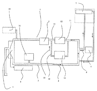
As is shown in figure 1, the apparatus 1 is provided with means, such as a
circulation
blower 2, for the circulating in one direction 4 in a line system 3 of
respiratory gas,
and of means 5, for instance a membrane or bellows, for varying the pressure
in the
CA 02776941 2012-04-05
WO 2011/043651 PCT/NL2010/000143
line system 3 in accordance with a certain respirating pattern to make
possible the
respiration of the patient 6.
Further means are provided, such as an apparatus 7, for determining the
composition
of the gas inhaled and the gas exhaled 8 by the patient. In the drawing is
shown the
5 principle of sampling removal. If so desired the gas that has been removed
can be
fed back into the system. It is also possible to make use of a measuring
system
directly in the gas inhaled and the gas exhaled 8. In the closed system by
means of
the sensor 9 the volume or the flow of the respiration by the patient can be
measured,
during spontaneous respiration as well as during breathing upon the patient or
in a
given case supportive breathing upon the patient. The apparatus 10 provides
the
supply of the gases and the vaporous anesthetica into the system.
In the example of the embodiment shown, in the line system 3, as seen in the
direction of circulation 4 of the respiratory gas, in front of the circulation
blower 2 a
line system part 11 is provided, in which is comprised the absorber device 12
for the
withdrawing of the carbon dioxide exhaled by the patient in the line system.
To the line system 3 further a by-pass line 13, extending parallel to the line
system
part 11, is connected, by means of which the respiratory gas can be led
completely or
partly outside the line system part 11 containing the absorber device 12. In
the by-
pass line 13 a regulating device 14 is provided, for instance a regulating
valve, by
means of which the ratio between the volume of the flow 15 of respiratory gas
through the by-pass line 13 and that through the absorber device 12 can be
adjusted.
By means of this the extent to which the patient breathes in gas that has been
purified
from carbon dioxide can be adjusted, and as a consequence thereof the amount
of
carbon dioxide in the body can be adjusted.
In the example of the embodiment shown at at least two places in the line
system
measuring devices are provided for the measuring of the concentration of CO2
in the
gas, whereby one measuring device 7 is provided near the mouth of the patient
6 and
a second measuring device 16 is provided in the part of the line system which,
as
seen in the direction 4 of the gas flow, is positioned behind the membrane or
bellows
5.
CA 02776941 2012-04-05
WO 2011/043651 PCT/NL2010/000143
6
By means of a control unit the operating of the regulating valve 14 takes
place in
dependence on the measurements of the concentration of carbon dioxide in the
respiratory gas at the mouth of the patient by the measuring device 7 and
further on
in the line system by the measuring device 16. On the basis of these
measurements
the regulating valve 14 is operated and by means of that the ratio between the
flow
of respiratory gas through the bypass line 13 and that through the absorber
device
12 is adjusted. By means of this the extent to which the patient breathes in
gas that
has not been purified from carbon dioxide is adjusted, and as a consequence
thereof
the amount of carbon dioxide in the respiratory gas at the end of a
respiratory
10 movement of the patient, de etCO2.
The determination of the end tidal concentration of CO2 through the
respiration is
dependant on the blood circulation. In adults the duration of one circulation
of the
blood is about 24 seconds; in infants about 9 seconds. The control system has
to be
15 quicker than the human, whereby a given is that for a significant change of
the
concentration of CO2 in the gas the length of time taken up by one circulation
of the
gas in the line system shall not be more than a third of the length of time
involved
with one circulation of the blood in the patient. Thus, a system for only
adults has to
remain below 24 seconds; for infants below 3 seconds.
A guiding principle is that one circulation of the gas in the line system does
not take
more than three seconds, preferably 2,5 seconds.
In this example of an embodiment the volume of the line system is 2,5 litre
while in
the line system a circulation blower is provided having in this example of an
embodiment a capacity of 60 litre per minute. This results in a circulation
time of:
2,5 litre/60 litre/min=0.042 minutes= 2,5 seconds.
Taking 2,5 seconds as a guiding principle, in the case of for instance a
volume of the
line system of 1,25 litre a circulation blower having a capacity of 30 litre
per minute
has to be applied, in the case of a volume of the line system of 5 litre a
circulation
blower having a capacity of 120 litre per minute has to be applied, and in the
case of
a volume of the line system of 0,625 litre a circulation blower having a
capacity of
15 litre per minute has to be applied.
CA 02776941 2012-04-05
WO 2011/043651 PCT/NL2010/000143
7
With the application of a circulation blower, the capacity of which is adapted
to the
volume of the circuit, it is possible to bring about and maintain a sufficient
fastness
of circulation. With this it is attained that the mixing is quicker than that
of the
processes in the patient, so that a quick and accurate regulation is possible
of the
etCO2. This is essential to an adequate control of the et C02, by which for
instance
during hyperventilation de et CO2 remains at the desired level,
notwithstanding
changing processes in the patient. By continuously measuring of the
concentration of
CO2 by means of the measuring devices 7 and 16 respectively at the mouth and
further on in the circuit it is possible to ascertain the correct functioning
of this quick
regulation.
With the apparatus according to the invention, more in particular the
application of a
circulation blower for providing a sufficiently fast circulation and the
control of the
ratio between the volume of the gas flow through the bypass line and that
through the
absorber device on the basis of measurements at at least two places in the
line
system, it is possible to adequately control the et CO2 irrespective of the
extent of
hyperventilation. Thereby the regulating valve with regard to the extent of
rebreathing in combination with the measurement of the end-tidal CO2 and the
intrinsic fastness of the system as a consequence of the application of a
circulation
blower, an adjustment which is faster than the changes of the processes in the
body
is attained.
In an example of an embodiment not shown in the drawing the regulating device
as
an alternative can also be provided in the line system part 11 in series with
the
absorber device 12.
In figure 2 an example of an embodiment is shown, in which next to the
regulating
device 14 in the by-pass line 13 in the line system part 11 a further
regulating device
17 is provided.
With the invention an apparatus is provided in which in parallel with the
absorber
device a by-pass line or rather by-pass is provided with either a regulating
device in
the flow through the absorber apparatus or a regulating device in the flow
through
the by-pass, and by means of which the breathing in again of carbon dioxide by
the
CA 02776941 2012-04-05
WO 2011/043651 PCT/NL2010/000143
8
patient (rebreathing of carbon dioxide) can be regulated, by means of which
the
amount of carbon dioxide in the respiratory gas at the end of a respiratory
movement
of the patient (et C02; endtidal C02) can be regulated at the desired physical
level,
while the ventilation is allowed to vary.
With the apparatus according to the invention by means of the increased
ventilation
the gases or in a given case vapours supplied to the patient can be increased
to attain
a faster wash in of the patient.
Further by means of the increased ventilation the gases or in a given case
vapours
given off by the patient into the system can be increased in order to obtain
attain a
quicker wash out of the patient.
20
30