Note: Descriptions are shown in the official language in which they were submitted.
CA 02777022 2015-10-19
51331-1200
MULTIPLE ORIENTATION BATTERY CONNECTOR
BACKGROUND
[00011 Batteries are commonly used to provide power to electronic
devices.
Typically, batteries are placed within a battery-operated device in a
particular orientation
to properly complete an electrical circuit. For example, some batteries have a
positive
terminal at one end of the battery and a negative terminal at the other end of
the battery,
and the battery must be properly oriented so that the battery terminals engage
appropriate
"
contacts of the device. Other battery configurations include positive and
negative
terminals adjacent one another or in relative positions/locations other than
at opposing
ends of a battery. Regardless of the particular configuration of the battery
and its
terminals, incorrectly orienting batteries within a device or with respect to
a battery
connector may not only yield an incomplete circuit rendering the battery-
operated device
unusable, but may also cause electrical or other damage to the components of
the device.
SUMMARY
[0002] Accordingly, the present description provides a connector for
electrically
coupling a battery with a battery-powered device. The connector includes first
and second
dual-contact assemblies, each of which includes a positive contact configured
to contact a
positive PP3 terminal of a PP3 battery and a negative contact configured to
contact a
negative PP3 terminal of the PP3 battery. Each dual-contact assembly is
configured so
that, when the dual-contact assembly is physically engaged with either of the
PP3 battery
terminals, one of the contacts of the dual-contact assembly electrically
engages the PP3
battery terminal, while the other of the contacts of the dual-contact assembly
is electrically
insulated from the PP3 battery terminal. Accordingly, the PP3 battery may be
installed
with the connector in either of two valid connection states, in which
appropriate electrical
connectivity is provided via the connector to a device to be powered by the
PP3 battery.
1
CA 02777022 2015-10-19
51331-1200
[0002a] According to one aspect of the present invention, there is
provided a connector
for electrically coupling a PP3 battery with a battery-powered device, the
connector
comprising: a first dual-contact assembly including a positive contact
configured to contact a
positive PP3 terminal of the PP3 battery and a negative contact configured to
contact a
negative PP3 terminal of the PP3 battery; and a second dual-contact assembly
including a
positive contact configured to contact the positive PP3 terminal of the PP3
battery and a
negative contact configured to contact the negative PP3 terminal of the PP3
battery, where
each of the first dual-contact assembly and the second dual-contact assembly
is configured
such that when the dual-contact assembly is physically engaged with the
positive PP3 terminal
of the PP3 battery, the positive contact of the dual-contact assembly
electrically engages the
positive PP3 terminal while the negative contact is electrically insulated
from the positive PP3
terminal, and where each of the first dual-contact assembly and the second
dual-contact
assembly is configured such that when the dual-contact assembly is physically
engaged with
the negative PP3 terminal of the PP3 battery, the negative contact of the dual-
contact
assembly electrically engages the negative PP3 terminal while the positive
contact is
electrically insulated from the negative PP3 terminal.
[0002b] According to another aspect of the present invention, there is
provided a device
configured to be electrically powered by a PP3 battery, the device comprising:
a circuit via
which the device receives and distributes electrical power from the PP3
battery to one or more
other components of the device; and a connector for electrically coupling the
PP3 battery to
the circuit, the connector including a first dual-contact assembly and a
second dual-contact
assembly, the connector being engageable with the PP3 battery in either of a
first valid state
and a second valid state, the first valid state being defined by the first
dual-contact assembly
being physically engaged with a positive PP3 terminal of the PP3 battery and
the second dual-
contact assembly being physically engaged with a negative PP3 terminal of the
PP3 battery,
the second valid state being defined by the first dual-contact assembly being
physically
engaged with the negative PP3 terminal of the PP3 battery and the second dual-
contact
assembly being physically engaged with the positive PP3 terminal of the PP3
battery, where
for each of the first dual-contact assembly and the second dual-contact
assembly, the dual-
la
CA 02777022 2015-10-19
51331-1200
contact assembly includes a positive contact electrically coupled with a
positive portion of the
circuit and a negative contact electrically coupled with a negative portion of
the circuit, the
positive contact and the negative contact being configured such that, when the
dual-contact
assembly is physically engaged with the positive PP3 terminal of the PP3
battery, the positive
contact is electrically coupled with the positive PP3 terminal while the
negative contact is
electrically insulated from the positive PP3 terminal, the positive contact
and the negative
contact of the dual-contact assembly being further configured such that, when
the dual-contact
assembly is physically engaged with the negative PP3 terminal of the PP3
battery, the
negative contact is electrically coupled with the negative PP3 terminal while
the positive
contact is electrically insulated from the negative PP3 terminal.
[0002c] According to still another aspect of the present invention,
there is provided a
connector for electrically coupling a battery with a battery-powered device,
the connector
comprising: a first dual-contact assembly including a positive contact
configured to contact a
positive terminal of the battery and a negative contact configured to contact
a negative
terminal of the battery; and a second dual-contact assembly including a
positive contact
configured to contact the positive terminal of the battery and a negative
contact configured to
contact the negative terminal of the battery, where each dual-contact assembly
is configured
so that, when the dual-contact assembly is physically engaged with either of
the battery
terminals, one of the contacts of the dual-contact assembly is radially biased
against a wall
portion of the engaged battery terminal, while the other of the contacts of
the dual-contact
assembly is spaced and electrically insulated from the engaged battery
terminal.
[0002d] According to yet another aspect of the present invention,
there is provided a
connector for electrically coupling a PP3 battery with a battery-powered
device, the connector
comprising: a first dual-contact assembly including a positive contact
configured to contact a
positive PP3 terminal of the PP3 battery and a negative contact configured to
contact a
negative PP3 terminal of the PP3 battery; and a second dual-contact assembly
including a
positive contact configured to contact the positive PP3 terminal of the PP3
battery and a
negative contact configured to contact the negative PP3 terminal of the PP3
battery, where
each of the first dual-contact assembly and the second dual-contact assembly
is configured
lb
CA 02777022 2015-10-19
51331-1200
such that when the dual-contact assembly is physically engaged with the
positive PP3 terminal
of the PP3 battery, the positive contact of the dual-contact assembly is sized
and configured to
cause resiliently-biased electrical engagement with an inner portion of the
positive PP3
terminal while the negative contact is electrically insulated from the
positive PP3 terminal,
where each of the first dual-contact assembly and the second dual-contact
assembly is
configured such that when the dual-contact assembly is physically engaged with
the negative
PP3 terminal of the PP3 battery, the negative contact of the dual-contact
assembly is sized and
configured to cause resiliently-biased electrical engagement with an outer
portion of the
negative PP3 terminal while the positive contact is electrically insulated
from the negative
PP3 terminal.
[0002e] According to a further aspect of the present invention, there
is provided a
connector for electrically coupling a battery with a battery-powered device,
the connector
comprising: a first dual-contact assembly including a positive contact
configured to contact a
positive terminal of the battery and a negative contact configured to contact
a negative
terminal of the battery; and a second dual-contact assembly including a
positive contact
configured to contact the positive terminal of the battery and a negative
contact configured to
contact the negative terminal of the battery, where each dual-contact assembly
is configured
so that, when the dual-contact assembly is physically engaged with either of
the battery
terminals, one of the contacts of the dual-contact assembly is radially biased
against a wall
portion of the engaged battery terminal to electrically engage the engaged
battery terminal,
while the other of the contacts of the dual-contact assembly is spaced and
electrically
insulated from the engaged battery terminal, where each dual-contact assembly
is configured
so that, when the dual-contact assembly is physically engaged with the
negative terminal of
the battery, the negative terminal of the battery is received within and at
least partially
surrounded by the negative contact of the dual-contact assembly, and the
positive contact of
the dual-contact assembly is configured so that, when the dual-contact
assembly is physically
engaged with the positive terminal of the battery, the positive contact of the
dual-contact
assembly is received within and at least partially surrounded by the positive
terminal of the
battery.
1 c
CA 02777022 2015-10-19
51331-1200
[00021] According to yet a further aspect of the present invention,
there is provided a
device configured to be electrically powered by a PP3 battery, the device
comprising: a circuit
via which the device receives and distributes electrical power from the PP3
battery to one or
more other components of the device; and a connector for electrically coupling
the PP3
battery to the circuit, the connector including a first dual-contact assembly
and a second dual-
contact assembly, the connector being engageable with the PP3 battery in
either of a first valid
state and a second valid state, the first valid state being defined by the
first dual-contact
assembly being physically engaged with a positive PP3 terminal of the PP3
battery and the
second dual-contact assembly being physically engaged with a negative PP3
terminal of the
PP3 battery, the second valid state being defined by the first dual-contact
assembly being
physically engaged with the negative PP3 terminal of the PP3 battery and the
second dual-
contact assembly being physically engaged with the positive PP3 terminal of
the PP3 battery,
where for each of the first dual-contact assembly and the second dual-contact
assembly, the
dual-contact assembly includes a generally cylindrical positive contact
electrically coupled
with a positive portion of the circuit and a generally cylindrical negative
contact electrically
coupled with a negative portion of the circuit, the positive contact and the
negative contact
being configured such that, when the dual-contact assembly is physically
engaged with the
positive PP3 terminal of the PP3 battery, the positive contact is received
within and partially
surrounded by an inner diameter portion of the positive PP3 terminal and is
electrically
coupled via resilient engagement with the inner diameter portion of the
positive PP3 terminal
while the negative contact is electrically insulated from the positive PP3
terminal, the positive
contact and the negative contact of the dual-contact assembly being further
configured such
that, when the dual-contact assembly is physically engaged with the negative
PP3 terminal of
the PP3 battery, the negative contact receives and partially surrounds an
outer diameter
portion of the negative PP3 terminal and is electrically coupled via resilient
engagement with
the outer diameter portion the negative PP3 terminal while the positive
contact is electrically
insulated from the negative PP3 terminal.
[0003] This Summary is provided to introduce a selection of concepts
in a simplified
form that are further described below in the Detailed Description. This
Summary is not
id
CA 02777022 2015-10-19
51331-1200
intended to identify key features or essential features of the claimed subject
matter, nor is it
intended to be used to limit the scope of the claimed subject matter.
Furthermore, the claimed
subject matter is not limited to implementations that solve any or all
disadvantages noted in
any part of this disclosure.
le
CA 02777022 2012-04-05
WO 2011/056500 PCT/US2010/053931
BRIEF DESCRIPTION OF THE DRAWINGS
[0004] Fig. 1 schematically shows a battery and battery-powered
device according
to the present description, including a connector for electrically coupling
the battery to a
circuit of the device.
[0005] Figs. 2 and 3 are exploded views of embodiments of a battery
connector
that may be used to electrically couple a battery to a battery-powered device.
[0006] Fig. 4 is a top view of a battery, shown together with certain
cross-
sectioned components of a battery connector that may be used to electrically
couple the
battery to a battery-powered device.
DETAILED DESCRIPTION
[0007] The present disclosure relates to a connector for electrically
coupling a
battery to a battery-powered device. As will be described with respect to
various
examples, the connector can be configured to enable valid operation regardless
of the
particular installed orientation of the battery. In many cases, the battery
will have two
terminals (positive and negative) that are to be connected to the battery-
powered device.
Typically, a pair of couplers or connection points is provided to facilitate
the connection,
thus presenting the possibility of physically orienting the battery relative
to the
device/connector in one of two different orientations. The connector examples
described
herein allow the battery to be validly connected in either orientation.
Specifically, in
either orientation, appropriate electrical connectivity is established to
permit device
operation and avoid the electrical/mechanical damage that can arise in prior
art connectors
that that allow for only one valid orientation.
[0008] In some previous solutions, users must insert batteries in a
particular
orientation, taking care to properly align positive and negative terminals
with
corresponding polarity-specific contacts (i.e., positive and negative) on the
device.
Although such previous solutions are at times accompanied by a diagram or
instructions
indicating proper battery orientation, it may be difficult to see such
instructions under
conditions where eyesight is compromised, such as poorly lit areas, or as may
be the case
for some elderly users. Additionally, such instructions may be difficult for
young children
to follow. Furthermore, following such diagrams each time batteries are
replaced in a
device that quickly goes through batteries may be unnecessarily time-consuming
and such
battery replacement may become frustrating to the user. As described above,
incorrectly
orienting batteries in such previous solutions not only renders the electrical
circuit
incomplete, but may also damage other electronic components of the device.
Thus, the
2
CA 02777022 2012-04-05
WO 2011/056500 PCT/US2010/053931
battery connector of the present disclosure includes dual-contact assemblies
configured to
validly accept batteries in either orientation, as described in more detail
hereafter.
[0009] Some of the examples herein will be discussed in the context
of a PP3
battery, also known as a 9-volt battery. In this battery configuration, the
body of the
battery is shaped as a rounded rectangular prism, and positive and negative
terminals are
provided next to each other on an end surface of the body/package of the
battery. The
negative PP3 terminal is relatively larger, and often is provided in a
generally cylindrical
form. More particularly, the negative PP3 terminal may be formed with a
hexagonal or
octagonal shape that can be snapped to a corresponding structure on a battery
connector.
The positive PP3 terminal is relatively smaller, and typically is also
generally cylindrical
but formed more specifically as a cylinder shape (i.e., typically without
hexagonal/octagonal features). The positive PP3 terminal typically is also
snapped or
similarly connected to a corresponding structure on a battery connector.
[0010] While the examples herein will often focus on a PP3 battery as
described
above, it will be appreciated that the present discussion is applicable to a
large extent to
other battery and terminal configurations, including cylindrical batteries,
coin-shaped
batteries, and/or batteries in other form factors and configurations.
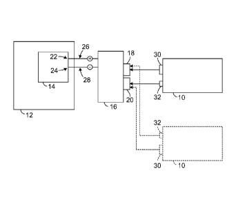
[0011] Fig. 1 schematically depicts a PP3 battery 10 and a device 12
that may be
electrically powered by the battery. Device 12 includes a circuit 14 via which
the device
receives and distributes electrical power from the battery to other components
of the
device. Also depicted is a connector 16 for electrically coupling battery 10
to the circuit
14 of device 12. Connector 16 typically includes a first dual-contact assembly
18 and a
second dual-contact assembly 20. As will be explained in further detail with
reference to
other figures, each of the dual contact assemblies includes a positive contact
which is
electrically coupled to a positive portion 22 of circuit 14 and a negative
contact which is
electrically coupled to a negative portion 24 of circuit 14. The connections
of these
contacts to the circuit are schematically shown in Fig. 1 as connections 26
and 28, which
are positive and negative, respectively.
[0012] The connector 16 may be engaged with PP3 battery 10 in either
of a first
valid state and a second valid state. The first valid state is indicated by
the solid-line
representation of battery 10, and is defined by the first dual-contact
assembly 18 being
physically engaged with a negative PP3 terminal 30 of battery 10, and the
second dual-
contact assembly 20 being physically engaged with a positive PP3 terminal 32
of battery
10. The second valid state is indicated by the dashed-line representation of
battery 10, and
3
CA 02777022 2012-04-05
WO 2011/056500 PCT/US2010/053931
is defined by the first dual-contact assembly 18 being physically engaged with
positive
PP3 terminal 32 of battery 10, and the second dual-contact assembly 20 being
physically
engaged with negative PP3 terminal 30 of battery 10.
[0013] In either of the first and second valid states shown in Fig.
1, appropriate
electrical connections are established between the PP3 battery and circuit 14.
Accordingly, in either state, appropriate electrical power is provided to
device 12, and the
arrangement avoids the potential damage that can occur in prior art systems as
a result of
installing a battery in an invalid orientation.
[0014] In typical embodiments, the appropriate electrical connections
are
established as a result of the engagement occurring between the dual-contact
assemblies
and the PP3 battery terminals. In particular, each dual-contact assembly is
configured so
that, when physically engaged with a positive PP3 battery terminal, the
positive contact of
the dual-contact assembly electrically engages the positive PP3 terminal,
while the
negative contact of the dual-contact assembly is electrically insulated from
the positive
PP3 terminal. Conversely, but similarly, when the dual-contact assembly is
engaged with
a negative PP3 battery terminal, the positive contact of the dual-contact
assembly is
electrically insulated from the negative PP3 terminal, while the negative
contact of the
dual-contact assembly electrically engages the negative PP3 terminal.
[0015] Fig. 2 depicts PP3 battery 10 with a further embodiment of a
connector 40
for electrically coupling battery 10 to a device. The components of connector
40 are
shown in an exploded view for clarity. Connector 40 includes a first dual-
contact
assembly 42, including a positive contact 44 for contacting a positive PP3
battery terminal
and a negative contact 46 for contacting a negative PP3 battery terminal. The
connector
also includes a second dual-contact assembly 52, including a positive contact
54 for
contacting a positive PP3 battery terminal and a negative contact 56 for
contacting a
negative PP3 battery terminal. As previously discussed, two valid connection
states are
permitted, in which either PP3 terminal can be validly electrically connected
to either
dual-contact assembly. Only one of the states/orientations is shown in Fig. 2
¨ i.e., an
orientation in which terminal 32 is aligned and engaged with dual-contact
assembly 52 and
terminal 30 is aligned and engaged with dual-contact assembly 42.
[0016] Contacts 44, 46, 54 and 56 may be mounted to a base structure
60, which
may also include a printed circuit board (PCB) or other connection mechanism.
Specifically, positive contacts 44 and 54 typically are connected together,
and/or to a
positive circuit connection on the device to be powered (e.g., positive
portion 22 of circuit
4
CA 02777022 2012-04-05
WO 2011/056500 PCT/US2010/053931
14 in Fig. 1). Similarly, negative contacts 46 and 56 typically are connected
together
and/or to a negative circuit connection of the device being powered (e.g.,
negative portion
24 of circuit 14 in Fig. 1). In addition, insulator structures 62 and 64 may
be provided, to
insulate each positive contact from each negative contact, and/or to hold the
positive
contact in a co-axial alignment or other desired orientation with respect to
the negative
contact. In addition to or instead of insulator structures, the contacts may
simply be held
in a spaced-apart orientation.
[0017] Contacts 44, 46, 54 and 56 may be generally cylindrical and/or
otherwise
adapted to physically engage with the generally cylindrical structure of the
positive and
negative PP3 battery terminals. For example, the negative contacts (i.e.,
contacts 46 and
56) may be configured to create an electrical connection by receiving and at
least partially
surrounding an outer diameter portion 32a of negative PP3 terminal 32. In
addition, the
negative contact may be sized or otherwise configured to provide a resiliently-
biased
engagement with the negative PP3 terminal. For example, a resilient metal may
be
employed for the negative contact. In addition, as in the depicted example,
notches or
cutaway portions may be employed to facilitate a resilient deformation of the
negative
contact, so as to provide a press-fit or other resilient engagement when the
negative PP3
terminal is received within the negative contact.
[0018] Similarly, the positive contacts (i.e., contacts 44 and 54)
may be configured
so that an electrical connection is created when one of them is received
within and at least
partially surrounded by an inner diameter portion 30a of positive PP3 battery
terminal 30.
As with the negative contacts, the positive contacts may be configured to
provide
resiliently-biased engagement with the positive PP3 terminal, so as to ensure
a reliable
electrical connection. Resilient engagement may be facilitated via choice of
conductive
material, and by providing notches or cutaways, as depicted on positive
contacts 44 and
54. As discussed with reference to Fig. 1, each of dual-contact assemblies 42
and 52 are
structured such that, when the dual-contact assembly is physically engaged
with positive
PP3 battery terminal, the positive contact electrically engages the positive
PP3 terminal
while the negative contact is insulated from the positive PP3 terminal, and
when the dual-
contact assembly is physically engaged with the negative PP3 battery terminal,
the
positive contact is insulated from the negative PP3 terminal while the
negative contact
electrically engages the negative PP3 terminal. Accordingly, regardless of
which
orientation the battery is placed in, appropriate electrical connectivity is
established
between the battery and device.
5
CA 02777022 2012-04-05
WO 2011/056500 PCT/US2010/053931
[0019] Fig. 3 depicts PP3 battery 10 with another embodiment of a
connector 80
for electrically coupling the PP3 battery to a device. As with Fig. 2, the
various
components that may be employed with the connector are shown in an exploded
view.
Fig. 3 is similar in many respects to Fig. 2. One point of contrast is that
positive contacts
82 and 84 are formed as part of a unitary conductive structure, along with
positive circuit
connection 86. Similarly, negative contacts 92 and 94 are formed unitarily,
along with
negative circuit connection 96. Insulator structures 102 and 104 may also be
provided, to
electrically insulate the two conductive structures from one another and hold
them in a
desired relative position to one another. In particular, the four structures
between battery
10 and base structure 110 may be assembled together in a stacked
configuration. Together
with base structure 112, base structure 110 may be used to support the battery
and
connector structures, and/or to provide electrical and physical connections to
components
of a battery-operated device.
[0020] Using the dual-contact assembly language of the prior
examples, positive
contact 82 and negative contact 92 define a first dual-contact assembly 122 of
connector
80, while a second dual-contact assembly 124 is defined by positive contact 84
and
negative contact 94. Also as in the prior examples, a valid electrical
engagement may be
created by connecting either PP3 terminal (30 or 32) of battery 10 to either
dual-contact
assembly (122 or 124). If a given one of the dual-contact assemblies is
engaged with the
positive PP3 terminal, its positive contact is connected to the positive PP3
terminal and its
negative contact is insulated from the positive PP3 terminal. On the other
hand, if the
dual-contact assembly is engaged with the negative PP3 terminal, its negative
contact is
electrically engaged with the negative PP3 terminal while its positive contact
is insulated
from the negative PP3 terminal. Also, similar to the embodiment of Fig. 2, the
contacts
may be generally cylindrical and/or otherwise configured to create resiliently-
biased
engagement with the generally cylindrical structures of the PP3 battery
terminals.
Regardless of which orientation the battery is placed in, appropriate
conductivity may be
provided to the device via positive circuit connection 86 and negative circuit
connection
96. These connections may correspond to connections 26 and 28, respectively,
of Fig. 1.
[0021] Fig. 4 shows a top plan view of battery 10, with its PP3 terminals
engaged
with the dual-contact assemblies of the connector embodiment of Fig. 3. In
particular, the
positive and negative contacts of dual-contact assemblies 122 and 124 are
shown in cross-
section. Negative PP3 terminal 32 is shown as being received within and at
least partially
surrounded by negative contact 94. The negative contact 94 makes electrical
contact with
6
CA 02777022 2012-04-05
WO 2011/056500 PCT/US2010/053931
the outer diameter or wall portion 32a of the terminal, and the electrical
engagement may
be maintained via a resiliently-biased engagement, as previously described. As
shown in
the figure, the biasing may occur radially in an inward direction against the
outer wall
region of the terminal. Meanwhile, the relative positions of negative contact
94 and
positive contact 84 result in the positive contact 84 being spaced and
insulated from
negative PP3 battery terminal 32. As previously discussed, the spacing and
insulating may
be provided by insulator structures 102 and 104 (not shown in Fig. 4).
[0022] Continuing with Fig. 4, positive contact 82 is shown as
received within and
at least partially surrounded by an inner diameter or wall portion 30a of
positive PP3
terminal 30. The positive contact 82 makes electrical contact with the
positive PP3
terminal, and the electrical connection may be established and maintained via
a resiliently-
biased engagement with the inner wall of the terminal, as previously
explained. Similar to
the negative contact, the connection of the positive contact may be maintained
via biasing
in a radial direction, or outward urging of the contact against the inner wall
region of the
positive battery terminal. The relative physical positions of positive contact
82 and
negative contact 92 result in the negative contact 92 being spaced and
insulated from
positive PP3 battery terminal 30. Although not depicted in Fig. 4, it should
be understood
that the connector embodiment of Fig. 2 may be engaged with a battery in a
manner
similar to that shown in Fig. 4.
[0023] In addition to or instead of the above examples, the contact
structures of the
dual-contact assemblies may be formed from and/or interconnected by wire or
wire-like
structures. For example, a wire contact may be employed to contact the inner
wall portion
of a positive PP3 terminal. Such a contact can be adapted to provide a spring-
maintained
or resiliently-biased connection to ensure electrical contact with the battery
terminal.
Similarly, a contact formed from wire or wire-like structures may be employed
to engage
an outer portion of a negative PP3 terminal. When employed, wire-type contacts
may or
may not involve a cylindrical shape or configuration, and the contacts may or
may not be
shaped to partially surround or be surrounded by the respective battery
terminal. Indeed, it
should be appreciated that various wire contact configurations may be employed
in
connection with the presently-described battery connectors.
[0024] It is to be understood that the configurations and/or
approaches described
herein are exemplary in nature, and that these specific embodiments or
examples are not to
be considered in a limiting sense, because numerous variations are possible.
The specific
routines or methods described herein may represent one or more of any number
of
7
CA 02777022 2012-04-05
WO 2011/056500 PCT/US2010/053931
processing strategies. As such, various acts illustrated may be performed in
the sequence
illustrated, in other sequences, in parallel, or in some cases omitted.
Likewise, the order of
the above-described processes may be changed.
[0025] The subject matter of the present disclosure includes all novel
and
nonobvious combinations and subcombinations of the various processes, systems
and
configurations, and other features, functions, acts, and/or properties
disclosed herein, as
well as any and all equivalents thereof
8