Note: Descriptions are shown in the official language in which they were submitted.
CA 02777258 2012-04-10
WO 2011/045781 PCT/IL2010/000767
TWIST DRILL
FIELD OF THE INVENTION
[001] The present invention relates to twist drills having shaped cutting
edges.
BACKGROUND OF THE INVENTION
[002] Self centering of a drill may be achieved by utilizing a known
principle: minimizing
a tangent angle, near the chisel edge, formed between a tangent to a cutting
edge and an axis
of rotation of the drill. Many different approaches have been taken in order
to achieve
optimal drill point geometry. The design of the cutting edges in general and
near the chisel
edge in particular is usually a tradeoff between toughness of the drill point
and the ability to
penetrate the workpiece efficiently. Drills having a generally sharper drill
point design will
generally penetrate the workpiece more easily but in most cases that may be at
the expense
of a more fragile drill point. A more robust, wider design of the drill point
will make it
sturdier but it may be more difficult for the drill point to pierce the
workpiece and center the
drill. An important aspect, dependant of drill point and cutting edge geometry
is the power
required to operate the drilling machine, more specifically, the axial power
required to
overcome the axial stress on the drill while machining.
[003] It is therefore an object of the present invention to provide new
cutting edge
geometry and drill point geometry that significantly reduces or overcomes the
aforementioned disadvantages.
SUMMARY OF THE INVENTION
[004] According to the present invention, there is provided a twist drill
having a rotation
axis A defining a forward to rear direction, the twist drill comprising a
cutting portion and a
drill body. The cutting portion comprises a chisel edge, a segment relief
surface, a chamfer
relief surface and at least two flutes extending longitudinally to the drill
body. Each flute
comprises a rake surface and a gash extending away from the chisel edge. The
cutting
portion further comprises at least two cutting segments, each cutting segment
comprising a
main cutting edge which includes a first cutting edge, a second cutting edge
and a chamfer
cutting edge. The gash and the segment relief surface meet at the first
cutting edge. The
rake surface and the segment relief surface meet at the second cutting edge
and the rake
-1-
CA 02777258 2012-04-10
WO 2011/045781 PCT/IL2010/000767
surface and the chamfer relief surface meet at the chamfer cutting edge. The
first and
second cutting edges are curved and the chamfer edge is straight.
[005] According to embodiments of the present invention, when proceeding along
the axis
of rotation A in a direction away from the chisel edge, each point of the main
cutting edge
projected on the axis of rotation A, is located farther from the chisel edge
than the point
before it.
[006] According to embodiments of the present invention, when proceeding along
the
main cutting edge in a direction away from the axis of rotation A, each point
on the main
cutting edge is located farther from the axis of rotation A than the point
before it.
[007] According to embodiments of the present invention, the segment relief
surface has a
concave shape defined by a relief radius RR.
[008] According to embodiments of the present invention, the drill body has a
diameter D
and the ratio of the relief radius RR to the diameter D is in the range of 50%
to 150%.
[009] According to embodiments of the present invention, the gash has first
and second
gash surfaces. The first gash surface meets the segment relief surface at the
first cutting
edge.
[0010] According to embodiments of the present invention, the first and second
gash
surfaces form an angle P therebetween. The angle P is in the range of 60 to
105 and
preferably is about 82 .
[0011 ] According to embodiments of the present invention, the first and
second gash
surfaces meet at a line L. The line L forming an angle y in the range of 20
to 50 and
preferably is about 32 with an axis of rotation A.
[0012] According to embodiments of the present invention, relative to the
chisel edge, any
given point on the main cutting edge is both rearward, and radially outward,
of all preceding
points on that main cutting edge.
BRIEF DESCRIPTION OF THE DRAWINGS
[0013] For a better understanding of the present invention and to show how the
same may
be carried out in practice, reference will now be made to the accompanying
drawings, in
which:
Fig. 1 is a partial isometric view of a twist drill according to embodiments
of the
present invention;
Fig. 2 is a side view of the twist drill shown in Fig. 1;
-2-
CA 02777258 2012-04-10
WO 2011/045781 PCT/IL2010/000767
Fig. 3 is an end view of the twist drill shown in Fig. 1;
Fig. 4 is a cross section taken along the line IV-IV of Fig. 3; and
Fig. 5 is a partial bottom isometric view of a twist drill according to
embodiments of
the present invention.
[0014] It will be appreciated that for simplicity and clarity of illustration,
elements shown
in the figures have not necessarily been drawn accurately or to scale. For
example, the
dimensions of some of the elements may be exaggerated relative to other
elements for
clarity, or several physical components may be included in one functional
block or element.
Further, where considered appropriate, reference numerals may be repeated
among the
figures to indicate corresponding or analogous elements.
DETAILED DESCRIPTION OF THE INVENTION
[0015] In the following description, various aspects of the present invention
will be
described. For purposes of explanation, specific configurations and details
are set forth in
order to provide a thorough understanding of the present invention. However,
it will also be
apparent to one skilled in the art that the present invention may be practiced
without the
specific details presented herein. Furthermore, well-known features may be
omitted or
simplified in order not to obscure the present invention.
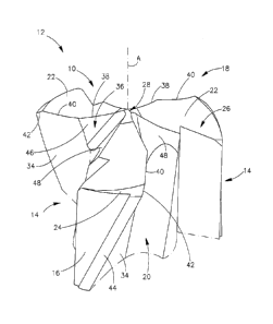
[0016] Reference is made to the figures in general and specifically to Fig. 1,
showing a
partial isometric view of a cutting portion 10 at a front end of a twist drill
12 having an axis
of rotation A and a diameter D, in accordance with embodiments of the
invention. The
twist drill 12 has a cylindrical drill body 14 and has a peripheral surface
16. The cutting
portion 10 may be part of a one-piece drill or a part of a replaceable cutting
head and may
be comprised of solid carbide. In accordance with some embodiments, the
cutting portion
10 has three identical cutting segments 18 and three identical flutes 20. The
cutting
segments 18 and flutes 20 are equally spaced circumferentially about the axis
of rotation A.
The axis of rotation A thus defines a forward-to-rear direction of the drill
body 14, with the
cutting portion 10 being at the forward end. Each flute 20 may have a helical
or straight
form and extends longitudinally along the drill body 14. In accordance with
other
embodiments the number of cutting segments 18 and flutes 20 may be different
from three,
for example, may be two, or four, or some other number.
-3-
CA 02777258 2012-04-10
WO 2011/045781 PCT/IL2010/000767
[0017] Each cutting segment 18 has a segment relief surface 22, which extends
radially
outwardly, away from the axis of rotation A to a chamfer relief surface 24.
The chamfer
relief surface 24 extends outwardly to the peripheral surface 16. The segment
relief surface
22 and the chamfer relief surface 24 form a main relief surface 26. At the
front end of the
twist drill 12 is located a chisel edge 28 which is defined by three chisel
sub-edges 30.
Each chisel sub-edge 30 is formed by intersection of two adjacent segment
relief surfaces
22. The flute 20 meets the main relief surface 26 at a main cutting edge 32,
also known as a
lip. Each flute 20 has a rake surface 34 and a gash 36 formed at the front end
of the flute
20.
[0018] The main cutting edge 32 is formed of three component cutting edges: a
first cutting
edge 38, a second cutting edge 40 and a chamfer cutting edge 42. The first
cutting edge 38
is formed at an interface of the gash 36 and the segment relief surface 22.
The second
cutting edge 40 is formed at an interface of the rake surface 34 and the
segment relief
surface 22. The chamfer cutting edge 42 is formed at an interface of the rake
surface 34 and
the chamfer relief surface 24. The rake surface 34 extends to the peripheral
surface 16
which may have a support wiper 44 which projects from the peripheral surface
16.
[0019] The first and second cutting edges 38, 40 are both curved. Although in
Fig. 3 it may
appear that the first cutting edge 38 is straight, it only appears to be
straight because in the
embodiment shown it has a very large radius of curvature. As can be seen in
Fig. 2 both the
first and second cutting edges 38, 40 are also concavely curved in a side
view. In
accordance with some embodiments the first and second cutting edges 38, 40 are
non-
identical. The curved nature of the first and second cutting edges 38, 40
gives unexpected
remarkable drilling results, in terms of centering and lowering machine power
requirements.
[0020] The segment relief surface 22 has a concave shape. In accordance with
some
embodiments, the concave shape is part of a sphere defined by a relief radius
RR (see Fig.
4). The ratio of the relief radius RR to the diameter D is in the range of 50%
to 150%. The
gash 36 has first and second gash surfaces 46, 48. According to some
embodiments, the
first gash surface 46 is planar. The first gash surface 46 meets the segment
relief surface 22
3o at the first cutting edge 38. The first and second gash surfaces 46, 48
form an angle I
therebetween (see Fig. 5). The first and second gash surfaces 46, 48 meet at a
line L which
forms an angle y with the axis of rotation A. In accordance with some
embodiments, the
-4-
CA 02777258 2012-04-10
WO 2011/045781 PCT/IL2010/000767
angle P may be in the range of 60 to 105 and preferably is 82 5 .
Independently, the
angle y may be in the range of 20 to 50 and preferably is 320 30
[0021] When proceeding along the axis of rotation A in a direction away from
the chisel
edge 28, each point of the main cutting edge 32 projected on the axis of
rotation A, is
located farther from the chisel edge 28 than the point before it. Thus,
relative to the chisel
edge 28, any given point on the main cutting edge 32 is rearward of all
preceding points on
that main cutting edge 32. Furthermore, when proceeding along the main cutting
edge 32 in
a direction away from the chisel edge 28, each point on the main cutting edge
32 is located
farther from the axis of rotation A than the point before it. Thus, relative
to the chisel edge
28, any given point on the main cutting edge 32 is radially outward of all
preceding points
on that main cutting edge 32.
[0022] While the present invention has been described with reference to one or
more
specific embodiments, the description is intended to be illustrative as a
whole and is not to
be construed as limiting the invention to the embodiments shown. It is
appreciated that
various modifications may occur to those skilled in the art that, while not
specifically
shown herein, are nevertheless within the scope of the invention.
-5-