Note: Descriptions are shown in the official language in which they were submitted.
CA 02777416 2012-05-11
1
TITLE OF THE INVENTION:
A method to recover LPG and condensates from refmeries fuel gas streams.
FIELD OF THE INVENTION
The present invention relates to a method that condenses and recovers low
pressure
gas (LPG) and condensates from fuel gas headers in oil refineries using Liquid
Natural Gas
(LNG) as a cryogenic process.
BACKGROUND OF THE INVENTION
Refineries process crude oil by separating it into a range of components, or
fractions, and then rearranging those into components to better match the
yield of each
fraction with market demand. Petroleum fractions include heavy oils and
residual
materials used to make asphalt or petroleum coke, mid range materials such as
diesel,
heating oil, jet fuel and gasoline, and lighter products such as butane
propane and fuel
gases. Refineries are designed and operated so that there will be a balance
between the
rates of gas production and consumption. Under normal operating conditions,
essentially
all gases that are produced are routed to the refinery fuel gas system,
allowing them to be
used for combustion equipment such as refinery heaters and boilers. Before the
fuel gas is
consumed at the refinery it is first amine treated to remove carbon dioxide
and hydrogen
sulfide before combustion. The treated typical refinery fuel gas systems are
configured so
that the fuel gas header pressure is maintained by using imported natural gas
to make up
the net fuel demand. This provides a simple way to keep the system in balance
so long as
gas needs exceeds the volume of gaseous products produced.
A typical refinery fuel gas stream is rich in hydrogen, C2+ and olefins. It is
well
known that gas streams can be separated into their component parts, involving
chilling,
expansion and distillation, to separate methane from heavier hydrocarbon
components.
Cryogenic processing of refinery fuel gas to recover valuable products
(hydrogen, olefins
and LPG) are a standard in the refining industry. Cryogenic processes in
practice provide
refrigeration by turbo-expansion of fuel gas header pressure re-compression
and or
mechanical refrigeration. Others have employed the use of membranes to first
separate
and produce a hydrogen stream and a hydrocarbon stream. In these cryogenic
mechanical
CA 02777416 2012-05-11
2
processes, there is a need for compression since typical fuel gas header
pressures vary
between 60 to 200 psi.
It is desirable therefore to have a process wherein the C2+ fractions from
refinery
fuel gas streams are efficiently and effectively separated as value added
products.
Cryogenic separation is typically viewed as being the most thermodynamically
efficient
separation technology. It is one of the first choices when higher value can be
obtained
from other products (olefins, LPG), especially when BTU removal from the fuel
gas
header system is of high priority. As, will be discussed, the present
invention provides a
process that achieves high product recoveries from refinery fuel gases
economically, both
in capital and operating costs. The process does not require feed or product
compression,
so its very reliable, pumps are the only rotating equipment. In addition, the
present
invention offers the ability to regulate a refinery gas variable pressure and
composition.
SUMMARY OF THE INVENTION
The claimed invention provides a method to cool and condense the C2+ fractions
from
a treated refinery fuel gas stream. First by cooling the fuel gas to ambient
temperature
through an air cooling fm-fan exchanger, secondly by pre-cooling the fuel gas
stream in a
plate fm exchanger, thirdly by adding and mixing a stream of Liquified Natural
Gas (LNG)
sufficient to meet the desired dew point of the C2+ fractions in the refmery
fuel gas stream.
The cooled refinery fuel gas stream is separated into a C2+ fraction and a C1-
fraction. The
cold C1" fraction is routed through the plate fin exchanger to give up its
cold in the pre-
cooling step before entering the fuel gas system. The C2+ fraction can be
routed to a
fractionation unit for products separation. The process can meet various modes
of
operation such as a C2" fraction and a C3+fraction streams, if so desired by
controlling the
temperature profile in the tower and LNG addition. At present, there is an
incentive for
the recovery of ethane as feed stock for the petrochemical industry.
In a preferred embodiment, the present invention is a process for the recovery
of
C2+ fractions from a hydrocarbon containing refinery fuel gas stream comprised
of
hydrogen and C1, C2, C3+ hydrocarbons, comprising:
CA 02777416 2012-05-11
3
(a) First cooling the treated refinery fuel gas stream to ambient temperature
in an air heat
exchanger, alternatively a cooling water heat exchanger can also be employed.
(b) Second by pre-cooling the fuel gas stream in a cold box, acting as a
reboiler to the
tower bottoms and as a condenser to the tower overhead stream.
(c) Third, the pre-cooled fuel gas stream is then mixed with a controlled
stream of LNG
to achieve the desired temperature to condense the desired liquids from the
fuel gas
stream. The mixture of liquids and gases enters a fractionation tower where
the gases
and liquids are separated. The liquids fraction is circulated through a
reboiler and
back to the tower to remove the light fraction in the stream. The gaseous
fraction is
stripped of its heavier components by a controlled reflux stream of LNG. The
exiting
produced cold vapour pre-cools the process feed gas giving up its cold energy
before
entering the fuel gas header.
A major feature of the invention is its ability to operate under varying
refinery flow rates,
feed compositions and pressures. Refinery fuel gas streams are variable since
they are
fed from multiple units. The inventive process can meet any refinery process
plant
variations, which are not uncommon in refinery fuel gas systems. The process
is not
dependent on plant refrigeration size and or equipment such as compressors
employed in
conventional LPG recovery processes.
The refrigeration plant is a supply of LNG which is added and directly mixed
with the
refinery fuel gas achieving the maximum heat transfer efficiency, the amount
of LNG
added is controlled on demand to meet desired product specs. Whereas, in
conventional
LPG recovery cryogenic plants, gas composition has an effect on the amount of
compression horsepower required; richer gas generally requires more horsepower
to
achieve the same recovery level than a leaner gas because of having more heavy
components. As inlet pressure decreases, more heat transfer area is required
to achieve the
same recovery level inside the cold box, as well, more exchanger area is
required for ethane
recovery than for propane recovery due to the higher amount of energy that
must be
transferred to cool the gas to the required temperatures.
Another benefit of the inventive process is the improvement of the refinery
fuel gas stream,
the reduced dew point of the fuel gas stream improves winter operations
significantly. Thus,
safety issues and operating difficulties associated with hydrocarbon
condensate are
eliminated.
CA 02777416 2012-05-11
4
As will hereinafter be described, the above method can operate at any refinery
fuel
gas operating conditions, resulting in substantial savings in both capital and
operating costs.
The above described method was developed with a view to recover LPG from
refinery fuel gas streams using LNG as a cryogenic process.
According there is provided a LPG recovery plant, which includes cooling the
refinery fuel gas stream to ambient temperature, pre-cooling the refinery fuel
gas by cross
exchange with fractionation unit bottom and overhead streams, adding and
mixing LNG to
directly cool and condense the desired liquid fractions, generating a two-
phase stream that
enters the fractionation unit. The fractionation unit is supplied at the top
tray with LNG on
demand as a reflux stream. At the bottom of the fractionation unit a reboiler
is provided to
fractionate the light fractions from the bottom stream. The trays in the
fractionation unit
provide additional fractionation and heat exchange thus facilitating the
separation. The
fractionator generates two streams, a liquid stream (LPG) and a very cold
vapour stream.
As will hereinafter be further described, the refinery feed gas is first
cooled to ambient
temperature, secondly, the ambient cooled refinery feed gas stream is pre-
cooled by the
fractionator bottoms reboiler stream and the fractionator overhead cold vapour
stream in a
counter-current flow. To the pre-cooled refinery feed gas stream, a stream of
LNG is added
and mixed with the refinery feed gas to meet a selected fractionation unit
operating
temperature. The fractionator overhead temperature is controlled by a LNG
reflux stream.
The fractionator bottoms temperature is controlled by a circulating reboiler
stream.
BRIEF DESCRIPTION OF THE DRAWINGS
These and other features of the invention will become more apparent from the
following description in which reference is made to the appended drawings, the
drawings are
for the purpose of illustration only and are not intended to in any way limit
the scope of the
invention to the particular embodiment or embodiments shown, wherein:
CA 02777416 2012-05-11
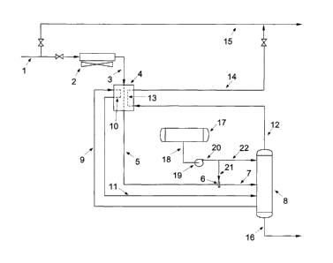
FIG. 1 is a schematic diagram of a gas liquids recovery facility equipped with
a heat
exchangers, a in-line mixer, a LNG storage bullet, pumps and a fractionator.
The LNG is
supplied to two locations; the in-line mixer and a reflux stream to the
fractionator.
FIG. 2 is a schematic diagram of a gas liquids recovery facility equipped with
a
5 variation in the process whereas LNG is added only as a reflux stream.
FIG. 3 is a schematic diagram of a gas liquids recovery facility equipped with
a
variation in the process whereas LNG is added only to the feed gas and mixed
before
fractionation.
DETAILED DESCRIPTION OF THE PREFERRED EMBODIMENT
The method will now be described with reference to FIG. 1.
As set for the above, this method was developed with a view for cryogenic
recovery
of C2+ fractions from typical refinery fuel gas streams. The description of
application of the
method should, therefore, be considered as an example.
Referring to FIG. 1, a refinery feed gas stream 1 is cooled to ambient
temperature in a
fin-fan air heat exchanger 2. The ambient cooled refinery feed gas stream 3
enters a heat
exchanger (cold box) 4. The heat exchanger (cold box) houses the reboiler
coils 10 and the
overhead condenser coils 13. The stream 3, is first pre-cooled by a
circulating reboiler stream
9 in a counter-current flow through coil 10, this counter-current heat
exchange, provides the
heat required to fractionate the bottoms stream while cooling the inlet
refinery gas stream.
The reboiler re-circulation stream 9 feed rate is controlled to meet
fractionator bottoms needs.
The refinery feed gas stream is further cooled by a stripped fractionator
overhead stream 12
in a counter-current flow through coil 13, this counter current heat exchange
substantially
cools the refinery feed gas stream. The pre-cooled refinery feed gas stream 5
exits heat
exchanger (cold box) 4 and flows through in-line mixer 6 where LNG stream 21
is added and
mixed as required to meet a selected stream temperature in stream 7. The two-
phase
temperature controlled stream 7, enters fractionator 8 to produce a vapour and
a liquid stream.
In this mode of operation the fractionator 8 overhead vapour stream 12 is
primarily a CI-
fraction. The fractionator 8 overhead temperature is controlled by a LNG
reflux stream
22. The trays in the fractionator 8 provide additional fractionation and heat
exchange thus
CA 02777416 2012-05-11
6
facilitating the separation. The bottoms temperature in Fractionator 8 is
controlled by a
circulating liquid stream 9 that gains heat through coil 10 in heat exchanger
(cold box) 4,
the heated circulating bottoms stream 11 is returned to the upper bottom
section of
fractionator 8 to be stripped of its light fraction. The fractionated liquid
stream 16 is
primarily a C2+ fraction, it exits fractionator 8 as its bottoms stream for
further
fractionation ie: a de-ethanizer, de-propanizer, etc...
The refrigerant used in the process is LNG which is stored in bullet 17. The
LNG is added to
the process through LNG feed line 18 to LNG pump 19. The pressurized LNG
stream 20
supplies LNG through stream 21 to a in-line mixer 6. The LNG stream 21 flow
rate is
controlled to meet a selected two-phase stream 7 temperature. Stream 21 is
added and mixed
with pre-cooled refmery gas stream 5 at in-line mixer 6 to produce a desired
temperature two-
phase stream 7. The LNG pressurized stream 21 also supplies LNG to reflux
stream 22 that
enters the top tray in fractionator 8. LNG reflux stream 22 controls the
temperature at the top
of fractionator 8.
A main feature of this invention is the simplicity of the process which
eliminates the use of
compression and expansion and or external refrigeration systems. Another
feature of the
invention is the flexibility of the process to meet various operating
conditions since only LNG
is added on demand to meet process operations parameters. The invention also
provides for a
significant savings in energy when compared to other processes since no
compression or
external refrigeration facilities are employed as in conventional cryogenic
processes. The
proposed invention can be applied at any refmery fuel gas plant size.
Referring to FIG. 2, the main difference from Fig.1, is the removal of in-line
mixer 6.
In this process mode, LNG is added only as a reflux stream to the top tray of
fractionator 8.
The temperature of the refmery feed gas stream 5 into fractionator 8 is fully
dependent on the
pre-cooling at heat exchanger (cold box) 4. The operation of the fractionator
8, bottoms is
controlled by a circulating reboiler flow rate stream 9, through coil 10, the
heated stream 11
flows back to the upper bottom section of fractionator 8, just as in FIG. 1.
The temperature at
the top of fractionator 8 is controlled by a LNG reflux stream 22. The trays
in the
fractionator 8 provide additional fractionation and heat exchange thus
facilitating the
separation. This process orientation provides an alternative method to
fractionate refmery
CA 02777416 2012-05-11
7
feed gas at albeit less efficiency than when using an in-line mixer 6 as shown
in Fig. 1.
Referring to FIG. 3, the main difference from FIG. 1 and FIG.2 is the removal
of the
reflux stream to the top of fractionator 8 and the removal of a circulating
reboiler stream from
the bottoms of fractionator 8. In this mode of operation, fractionator 8
becomes a simple
gas/liquid separator where both vapour and liquid streams are not
fractionated. This simple
mode of operation allows for the recovery of LPG and reduction of the dew
point in refinery
fuel gas for combustion.
In this patent document, the word "comprising" is used in its non-limiting
sense to
mean that items following the word are included, but items not specifically
mentioned are not
excluded. A reference to an element by the indefmite article "a" does not
exclude the
possibility that more than one of the element is present, unless the context
clearly requires that
there be one and only one of the elements.
The scope of the claims should not be limited by the preferred embodiments set
forth
in the examples, but should be given a broad purposive interpretation
consistent with the
description as a whole.