Some of the information on this Web page has been provided by external sources. The Government of Canada is not responsible for the accuracy, reliability or currency of the information supplied by external sources. Users wishing to rely upon this information should consult directly with the source of the information. Content provided by external sources is not subject to official languages, privacy and accessibility requirements.
Any discrepancies in the text and image of the Claims and Abstract are due to differing posting times. Text of the Claims and Abstract are posted:
| (12) Patent: | (11) CA 2777533 |
|---|---|
| (54) English Title: | DRILLING SCREW |
| (54) French Title: | VIS PERCEUSE |
| Status: | Granted |
| (51) International Patent Classification (IPC): |
|
|---|---|
| (72) Inventors : |
|
| (73) Owners : |
|
| (71) Applicants : |
|
| (74) Agent: | NORTON ROSE FULBRIGHT CANADA LLP/S.E.N.C.R.L., S.R.L. |
| (74) Associate agent: | |
| (45) Issued: | 2017-06-06 |
| (86) PCT Filing Date: | 2010-09-27 |
| (87) Open to Public Inspection: | 2011-04-28 |
| Examination requested: | 2015-07-27 |
| Availability of licence: | N/A |
| (25) Language of filing: | English |
| Patent Cooperation Treaty (PCT): | Yes |
|---|---|
| (86) PCT Filing Number: | PCT/EP2010/064249 |
| (87) International Publication Number: | WO2011/047933 |
| (85) National Entry: | 2012-04-12 |
| (30) Application Priority Data: | ||||||
|---|---|---|---|---|---|---|
|
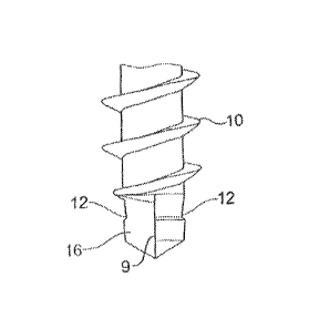
A drilling screw contains on its front end facing away
from the screw head a drill bit having two drilling
cutters. At an axial distance from the drilling cutters
the screw shank has a constriction, within which the
diameter of the screw shank is smaller than the
diameter of the hole produced by the drill bit. The
constriction is configured such that it has a shoulder
running almost transversely to the longitudinal axis
and facing the screw head and from which the diameter
gradually approaches again the core diameter of the
shank. Within this constriction begins the thread,
wherein the thread edge initially has a distance from
the longitudinal axis of the screw which corresponds
roughly to the radius of the hole. The thread edge then
runs along a spiral up to the final outer diameter of
the thread on the shank.
L'invention concerne une vis perceuse présentant, sur son extrémité avant opposée à la tête de vis, un trépan (7) muni de deux lames (8). La tige de vis présente, à une distance axiale des lames (8), un rétrécissement (12), dans lequel le diamètre de la tige de vis est inférieur au diamètre du trou formé par le trépan (7). Le rétrécissement (12) est conçu de manière à présenter un épaulement qui est tourné vers la tête de vis et s'étend de manière pratiquement transversale à l'axe longitudinal, épaulement à partir duquel le diamètre se rapproche à nouveau progressivement du diamètre intérieur de la tige. Le filetage (6) commence dans ce rétrécissement (12), l'arête de filetage présentant tout d'abord, à partir de l'axe longitudinal de la vis, une distance correspondant approximativement au rayon du trou. L'arête de filetage s'étend ensuite le long d'une spirale jusqu'au diamètre final extérieur du filetage (6) sur la tige.
Note: Claims are shown in the official language in which they were submitted.
Note: Descriptions are shown in the official language in which they were submitted.
For a clearer understanding of the status of the application/patent presented on this page, the site Disclaimer , as well as the definitions for Patent , Administrative Status , Maintenance Fee and Payment History should be consulted.
| Title | Date |
|---|---|
| Forecasted Issue Date | 2017-06-06 |
| (86) PCT Filing Date | 2010-09-27 |
| (87) PCT Publication Date | 2011-04-28 |
| (85) National Entry | 2012-04-12 |
| Examination Requested | 2015-07-27 |
| (45) Issued | 2017-06-06 |
There is no abandonment history.
Last Payment of $263.14 was received on 2023-12-13
Upcoming maintenance fee amounts
| Description | Date | Amount |
|---|---|---|
| Next Payment if small entity fee | 2025-09-29 | $253.00 |
| Next Payment if standard fee | 2025-09-29 | $624.00 |
Note : If the full payment has not been received on or before the date indicated, a further fee may be required which may be one of the following
Patent fees are adjusted on the 1st of January every year. The amounts above are the current amounts if received by December 31 of the current year.
Please refer to the CIPO
Patent Fees
web page to see all current fee amounts.
| Fee Type | Anniversary Year | Due Date | Amount Paid | Paid Date |
|---|---|---|---|---|
| Application Fee | $400.00 | 2012-04-12 | ||
| Maintenance Fee - Application - New Act | 2 | 2012-09-27 | $100.00 | 2012-09-11 |
| Maintenance Fee - Application - New Act | 3 | 2013-09-27 | $100.00 | 2013-08-15 |
| Maintenance Fee - Application - New Act | 4 | 2014-09-29 | $100.00 | 2014-08-28 |
| Request for Examination | $800.00 | 2015-07-27 | ||
| Maintenance Fee - Application - New Act | 5 | 2015-09-28 | $200.00 | 2015-08-14 |
| Maintenance Fee - Application - New Act | 6 | 2016-09-27 | $200.00 | 2016-08-30 |
| Final Fee | $300.00 | 2017-04-19 | ||
| Maintenance Fee - Patent - New Act | 7 | 2017-09-27 | $200.00 | 2017-09-19 |
| Maintenance Fee - Patent - New Act | 8 | 2018-09-27 | $200.00 | 2018-09-17 |
| Maintenance Fee - Patent - New Act | 9 | 2019-09-27 | $200.00 | 2019-09-16 |
| Maintenance Fee - Patent - New Act | 10 | 2020-09-28 | $250.00 | 2020-09-14 |
| Maintenance Fee - Patent - New Act | 11 | 2021-09-27 | $255.00 | 2021-09-13 |
| Maintenance Fee - Patent - New Act | 12 | 2022-09-27 | $254.49 | 2022-09-19 |
| Maintenance Fee - Patent - New Act | 13 | 2023-09-27 | $263.14 | 2023-09-18 |
| Maintenance Fee - Patent - New Act | 14 | 2024-09-27 | $263.14 | 2023-12-13 |
Note: Records showing the ownership history in alphabetical order.
| Current Owners on Record |
|---|
| SWG SCHRAUBENWERK GAISBACH GMBH |
| Past Owners on Record |
|---|
| None |

