Note: Descriptions are shown in the official language in which they were submitted.
CA 02777594 2012-04-13
WO 2011/044692 PCT/CA2010/001633
SYSTEM AND METHOD FOR MANAGING APPLICATIONS FOR MULTIPLE
COMPUTING ENDPOINTS AND MULTIPLE ENDPOINT TYPES
[0001] This application claims priority to U.S. Provisional Application No.
61/251,883
filed on October 15, 2009, the contents of which are incorporated herein by
reference.
TECHNICAL FIELD
[0002] The following relates to systems and methods for managing applications
for
multiple computing endpoints and multiple endpoint types.
BACKGROUND
[0003] The proliferation of mobile computing, for example using smart phones,
laptop
computers, and even in-vehicle systems, has increased the demand for mobile
applications.
Mobile applications tend to provide users with an experience that can appear
seamless and
visually appealing by taking advantage of the local computing hardware such as
GPS,
camera, video, etc. The downside of mobile applications from the
administrative standpoint
is that they can be expensive to develop and maintain and may need to be
developed
separately for different platforms. From the user's perspective, maintaining
mobile
applications can also be burdensome by requiring user intervention in order to
update the
local software, install patches, etc.
[0004] In contrast to the development of platform-specific mobile
applications, mobile
web or WAP based counterparts can be deployed. Mobile web pages utilize mobile
browsing capabilities to display content in a browser according to the way it
is rendered by
the web-based application. Mobile web pages typically provide the same content
regardless
of which type of platform you are viewing it on and, as such, the smart phone
user may have
a degraded experience when compared to a desktop or laptop with a larger
screen. Despite
having a user experience that may be less preferred than a platform-specific
mobile
application, mobile web pages are typically significantly less inexpensive to
develop,
maintain, and deploy. The mobile web environment allows administrators to
update content
and user interfaces (UI) without the need for user intervention since the user
is accessing
the content directly through their browser.
[0005] It is therefore an object of the following to address the above-noted
disadvantages.
-1-
CA 02777594 2012-04-13
WO 2011/044692 PCT/CA2010/001633
SUMMARY
[0006] In one aspect, there is provided a method for providing applications on
multiple
endpoint types, the method comprising: providing a runtime module capable of
creating a
user interface for an endpoint application from instructions provided in a
communications
protocol; and using the communications protocol to receive requests for
content, logic, and
user interface data, and to provide replies to the runtime module.
[0007] In another aspect, there is provided a method for providing
applications on
multiple endpoint types, the method comprising: obtaining a runtime module
capable of
creating a user interface for an endpoint application using instructions
provided in a
communications protocol; sending a request to an application server pertaining
to use of the
endpoint application; receiving a reply in accordance with the communications
protocol with
the instructions; and parsing the instructions to generate the user interface.
[0008] In yet another aspect, there is provided a method for enabling
interactivity with an
endpoint application, the method comprising: obtaining a message sent in
response to a
detected event; interpreting the message to determine one or more instructions
for
responding to the detected event; and providing the instructions to native or
custom
application programming interfaces (APIs) to perform a response to the event.
[0009] Computing devices, systems, and computer readable media configured to
perform such methods are also provided.
BRIEF DESCRIPTION OF THE DRAWINGS
[0010] Embodiments will now be described by way of example only with reference
to
the appended drawings wherein:
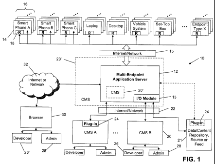
[0011] Figure 1 is a block diagram of an exemplary system for managing
applications for
a plurality of endpoints and endpoint types.
[0012] Figure 2 is a block diagram illustrating further detail of the
application server
shown in Figure 1.
[0013] Figure 3 is a block diagram illustrating further detail of the
application server core
shown in Figure 2.
-2-
CA 02777594 2012-04-13
WO 2011/044692 PCT/CA2010/001633
[0014] Figure 4A is a block diagram illustrating further detail of a content
management
system (CMS) shown in Figure 1.
[0015] Figure 4B is a block diagram illustrating further detail of a
content/data repository,
source or feed shown in Figure 1.
[0016] Figure 5 is a block diagram illustrating further detail of an endpoint
shown in
Figure 1.
[0017] Figure 6 is a block diagram illustrating further detail of a portion of
the endpoint
shown in Figure 5.
[0018] Figure 7 is a block diagram illustrating further detail of another
portion of the
endpoint shown in Figure 5.
[0019] Figure 8 is a schematic diagram illustrating a distribution of kernel
logic for each
application within an endpoint.
[0020] Figure 9 is flow diagram illustrating a runtime translation of an
endpoint mark-up
language (EML) document into instructions utilizing features on an endpoint.
[0021] Figure 10A is a schematic diagram illustrating a hierarchy for a
collection used in
the EML format.
[0022] Figure 10B is a schematic diagram illustrating a hierarchy for data
encoding using
the EML format.
[0023] Figure 11 is a schematic diagram illustrating a hierarchy for a themes
collection
definition.
[0024] Figure 12 is a schematic diagram illustrating a hierarchy for a views
collection
definition.
[0025] Figure 13 is a schematic diagram for a socket instance definition.
[0026] Figure 14 is a schematic diagram for a field instance definition.
[0027] Figure 15 is a schematic diagram for a button field instance
definition.
[0028] Figure 16 is a schematic diagram for a label field instance definition.
-3-
CA 02777594 2012-04-13
WO 2011/044692 PCT/CA2010/001633
[0029] Figure 17 is a schematic diagram for a list box instance definition.
[0030] Figure 18 is a block diagram illustrating an exemplary layout for a
smart phone
comprising a label field, socket, and button.
[0031] Figure 19 is a flow diagram illustrating exemplary computer executable
instructions for managing applications on multiple endpoints and endpoint
types.
[0032] Figure 20 is a flow diagram illustrating exemplary computer executable
instructions for creating a new endpoint type.
[0033] Figure 21 is a flow diagram illustrating exemplary computer executable
instructions for the application server in Figure 1 processing a request for
content at runtime
and returning a EML document.
[0034] Figure 22 is a flow diagram illustrating exemplary computer executable
instructions for launching a mobile application at an endpoint utilizing the
runtime module
shown in Figure 1.
[0035] Figure 23 is a schematic diagram illustrating handling of AWOM messages
using
the AWOM interpreter shown in Figure 7.
[0036] Figure 24 is a schematic diagram showing an example use case for the
system
shown in Figure 1.
[0037] Figure 25 is a schematic diagram showing another example use case for
the
system shown in Figure 1.
[0038] Figure 26 is a flow diagram illustrating example computer executable
instructions
for converting media files to requested formats on the fly.
DETAILED DESCRIPTION OF THE DRAWINGS
[0039] It has been recognized that the advantages of platform-specific mobile
applications can be combined with advantages of mobile web-based solutions to
facilitate
the development, deployment, and maintenance of mobile applications. As will
be described
further below, by combining these advantages, a single endpoint application
can be centrally
maintained and its content made available to multiple endpoints and multiple
endpoint types.
In this way, each endpoint application only needs to be developed once and can
be
-4-
CA 02777594 2012-04-13
WO 2011/044692 PCT/CA2010/001633
managed from a single location without duplicating content or resources. An
endpoint or
medium may refer to any form of technology, both software and hardware and
combinations
thereof, that has the ability to utilize a endpoint application. The endpoint
may be, for
example, a smart phone, web browser, laptop/tablet PC, desktop PC, set-top
box, in-vehicle
computing system, RSS feed, social network, etc.
[0040] A multi-endpoint application server is provided that allows
administrators to
create and update content such as data, UI, styling, flow, etc., for endpoint
applications
using content management capabilities (e.g. via a content management system
(CMS)) that
allows the administrators to control how the endpoint application should be
presented and
how it should behave for various end-point types. This allows administrators
to create a fully
branded experience that exists on the user's endpoint device as a endpoint
application as if
it were programmed specifically for the platform which the endpoint device
utilizes. The
application server can be implemented with its own CMS or an existing CMS used
by that
administrator to allow the administrator to manage content in a way that is
familiar to them.
A global application server can be deployed to service multiple clients or an
enterprise
server can be deployed to manage content and applications for an enterprise
which interacts
with multiple endpoint types.
[0041] The application server described below provides a mechanism by which a
endpoint application can be updated with new content, and have its entire user
experience
from UI to functionality modified from a single "portal" on the server side.
Therefore, the cost
of developing new branded endpoint applications can be reduced and the cost of
maintaining and updating the endpoint application can also be significantly
reduced, in
particular as more and more endpoint types are added. For the administrator, a
runtime
application can be provided to each endpoint, which is configured to obtain
content that is
managed and maintained from the server in the same way as a normal web browser-
based
application would. To enable such multiple endpoint types to experience the
same or similar
endpoint application experience, the multi-endpoint application server accepts
requests from
the runtime application and determines what kind of endpoint is making the
request such
that it can present the content to the runtime application in a manner that is
deemed
appropriate for the endpoint type. In this way, the process can be made
transparent to the
user and thus seamless from the user's perspective. The administrator can
easily configure
the process and simplify the day-to-day management of content for multiple
endpoint types
and should be able to configure pre-existing endpoint types and be able to add
new endpoint
types to the system as they are needed.
-5-
CA 02777594 2012-04-13
WO 2011/044692 PCT/CA2010/001633
[0042] As will be described below, in order to facilitate multiple endpoint
types, the
system that will be herein described utilizes a content communication protocol
for handling
communications between the multi-endpoint application server and the various
endpoint
types, and a runtime application on the endpoint that will interact with the
application server
to obtain new content and UI definitions. For ease of reference, the computer
language
utilized by the content communication protocol may be referred to as Endpoint
Mark-Up
Language (EML).
[0043] Referring now to Figure 1, an endpoint application management system is
denoted generally by numeral 10, and may hereinafter be referred to as the
"system 10".
The system 10 comprises a multi-endpoint application server 12, which may
hereinafter be
referred to as the "application server 12" for brevity. The application server
12 is interposed
between one or more but typically a plurality of endpoints 14 which are also
typically of
multiple endpoint types 16 and a CMS 20 (which may or may not reside on or
near the
application server 12) and/or a data/content repository, source or feed 21. In
the example
shown in Figure 1, several endpoint types 16 are illustrated, including three
different types of
smart phones (A, B, C), laptops, desktops, vehicle systems, set-top boxes
(e.g. for cable
television), along with a generic endpoint type X. It can be appreciated that
as noted above,
an endpoint 14 can represent any software, hardware, or combination thereof
that utilizes
some form of application, for example a "mobile application" that is also
available to various
other endpoint types 16 with a similar user experience.
[0044] Figure 1 illustrates several different configurations of the
application server 12
and CMS 20. In one configuration of the CMS 20', it may reside on the
application server
12, and in another configuration, the application server 12 may be part of or
otherwise
programmed into the CMS 20". In yet another, more typical configuration, the
application
server 12 is separate from one or more CMSs 20. It will be appreciated that
the application
server 12 can be a dedicated server per CMS 20 or can service multiple CMSs 20
as
illustrated in Figure 1. As such, a global or "common" application server 12
can be deployed
to provide a central service, or an enterprise or "custom" application server
12 can be
deployed to provide specific services to a single entity. Similar
configurations are also
applicable to the data/content repository, source or feed 21 (which for ease
of reference will
hereinafter be referred to as a "source" 21).
[0045] In this example, the CMS 20 and source 21 may comprise a plug-in 24,
which
provides a suitable interface for communicating with the existing features and
infrastructure
-6-
CA 02777594 2012-04-13
WO 2011/044692 PCT/CA2010/001633
provided by an existing CMS type. In other embodiments, an I/O module 13 may
be used at
the application server 12 to translate or convert native data or content in
whatever format to
one that is familiar to the application server 12. In further embodiments, the
CMS 20 or
source 21 may already be in the proper format and thus no plug-in 24 or I/O
module 13 may
be needed (see also Figures 4A and 4B).
[0046] The CMS 20 typically provides access to developers 26 and
administrators
(Admin) 28 for developing, deploying, and maintaining content for the endpoint
applications.
A runtime module 18 is provided on each endpoint 14, which provides the
runtime logic
necessary to request content and data from the application server 12 and
provide the
endpoint application features to the user of the endpoint 14. In this way, the
endpoint 14
does not have to maintain current views, styling and logic for each
application it uses but
instead can rely on the maintenance of the application content at the
application server 12.
This also enables multiple endpoint types 16 to receive a similar user
experience, regardless
of the platform. For example, a centrally managed endpoint application can be
deployed on
Apple, Blackberry, and Palm devices without having to separately develop an
application for
each platform.
[0047] As shown in Figure 1, communications between the endpoints 14 and the
application server 12 are facilitated by connectivity over the Internet or
other suitable
network 15 as is well known in the art. Similarly communications between the
application 12
and the CMSs 20 are facilitated by connectivity over the Internet or other
suitable network
22. It can be appreciated that the networks 15, 22 can be the same or
different. For
example, the network 15 may be a wireless network, whereas the network 22 may
be a
wireline service or hybrid of the two. Also, future networks may employ
different standards
and the principles discussed herein are applicable to any data communications
medium or
standard.
[0048] The application server 12 may provide its own CMS services (e.g. by
incorporating CMS 20') or may otherwise enable direct interactions with
developers 26' and
administrators (Admin) 28', e.g. through a browser 30 connectable to the
application server
12 through the Internet or other suitable network 32. In this way, the
application server 12
can service individuals that do not necessarily rely on or require the
capabilities of a CMS
20. Similarly, admin 28' may be required to service the applications deployed
and managed
by the application server 12 or to service and maintain the application server
12 itself.
-7-
CA 02777594 2012-04-13
WO 2011/044692 PCT/CA2010/001633
[0049] Further detail of one configuration for the application server 12 is
shown in Figure
2. The application server 12 in this configuration has a network component 36
providing an
interface between an application server core 34 and the various endpoints 14
and endpoint
types 16. This allows the application server core 34 to receive content and
data requests 37
from the endpoints 14 and to return data and UI responses 35 thereto. The
application
server 12 also comprises a browser front end 42 which enables the admin 28'
and
developers 26' to interact with the application server core 34. Alternatively,
any other
application programming interface (API) (not shown) can be used to provide a
portal into the
application server core 34 to users with the appropriate permissions. In this
example, when
relying on a CMS 20, the application server 12 may obtain content and other
data from the
CMS 20, through the I/O module 13, wherein the CMS 20 stores such content and
data in a
content database 40. Alternatively, or in addition to, the application sever
12 may have its
own content store 38. In yet another alternative, the application server 12
may have a
content cache 38 that temporarily stores content to avoid repeated requests to
the CMS 20
for the same content.
[0050] Figure 2 also illustrates a global unique identifier (GUID) server 15.
As will be
discussed further below, each instance of an application on an endpoint 14 can
be given an
ID (GUID). Each application may thus be assigned a GUID when it makes is first
(initial)
request to the endpoint application server 12. The GUID server 15 can be used
to prevent
two instances (even with the same name) having a conflict on the endpoint 14.
For
example, data storage on the endpoint 14 can be indexed by GUID such that each
application can be assured that its data store belongs only to itself and no
other application.
This can isolate each application from one another and also allow the
application server 12
to identify each endpoint application as it makes a request and allow for
analytical tracking
such as usage, advertising statistics, etc. The GUID server 15 can be an
external server as
shown in Figure 2 and can be made responsible for generating GUIDs to manage
and
distribute GUIDs to endpoints 14. This configuration can be used to ensure
that all GUIDs
for all endpoint applications are generated from the same server. In other
words, the GUID
server 15 can be used as a certification server whose responsibility is to
verify if an endpoint
application is valid and accordingly generate GUIDs. This creates a central
"control hub" for
managing all endpoint applications.
[0051] Turning now to Figure 3, an exemplary configuration for the application
server
core 34 is shown. The server core 34 comprises an administrative engine 44,
which is
responsible for handling requests 37, obtaining the necessary
content/UI/logic, definitions,
-8-
CA 02777594 2012-04-13
WO 2011/044692 PCT/CA2010/001633
configurations and other data, and providing responses 35. The administrative
engine 44
uses an endpoint request manager 46 to manage incoming requests 37 from the
endpoints
14 to determine what kind of endpoint 14 is making the request 37. Once it
knows the
endpoint type 16, the administrative engine 44 then uses the configuration
manager 48 to
get the necessary configuration 51 for that endpoint type 16. The
CMS/repository manager
53 is then called to obtain content or data from the source 21, CMS 20, etc.
The content is
then combined with the associated logic obtained by an endpoint logic manager
43 and
combined with the associated UI definitions obtained by an endpoint UI manager
55 and the
content is mapped using a content mapping manager 57. The content mapping
manager is
used in situations where the CMS 20 or the source 21 is not an integral part
of the
application server 12 such that external data and content types can be mapped
to content
items used in the application server 12. This is particularly important where
external sources
21 or CMSs 20 use data or a format that is not familiar or regularly used in
the application
server 12. The content mapping manager 57 can thus be used to translate
external data to
a format common to the application server 12. The endpoint UI manager 55 is
used to
determine what kind of UI "view" definitions should be loaded given the
content being
requested and the endpoint type 16 of the requestor. A reporting engine 59 may
also be
used, in conjunction with a 3rd party entity 49 (if applicable) to keep track
of analytical data
sent from the endpoint 14 and generate usage reports from data provided in the
request 37.
[0052] The content + UI + logic (and report if applicable) is then passed to a
content +UI
+ logic renderer 62 to generate a data package to be sent back as a response
35 as will be
explained in greater detail below. An advertising engine 45 may also be called
where
appropriate to add advertising content, e.g. obtained from a 3rd party
advertising source 47 (if
applicable). An I/O manager 33 may also be used, e.g. where data and content
provided by
the CMS 20 or source 21 needs to be translated or converted at the server
side. An endpoint
application distribution manager 60 is also provided for managing the
distribution of kernel
logic 61 for installing a runtime module 18 on the various endpoints 14.
[0053] The administrative engine 44 therefore gathers the necessary
configurations and
mappings as well as the content and data itself for the particular endpoint
application, and
provides these components to the renderer 62 to generate a suitable response
35 for the
requesting endpoint 14.
[0054] Figure 4A illustrates additional detail of one configuration for a CMS
20. As noted
above, the CMS 20 may use a plug-in 24 to enable the application server 12 to
communicate
-9-
CA 02777594 2012-04-13
WO 2011/044692 PCT/CA2010/001633
with the CMS platform 64 to avoid having to reconfigure or re-program the CMS
20. It will be
appreciated that the plug-in 24 is typically a piece of custom code that would
be written to
make non-compatible CMSs 20 and sources 21 work with the application server
12. As
shown in Figure 4A, the CMS 20 may utilize the plug-in 24 in some embodiments,
but may
instead provide its native data directly to the application server 12 to be
converted or
translated by the I/O module 13. In other configurations, e.g. when the CMS 20
is integral to
the application server 12, a familiar format of data/content can be sent
directly to the
application server core 34 without requiring any translation. It may be noted
that the plug-in
24 is particularly advantageous for unlocking content or data that is held by
an otherwise
isolated source 21. For example, a vehicle may provide data that can be used
for a traffic
application and the plug-in 24 can be written to enable that data to be
provided to the
application server 12. Also, in the CMS environment, the plug-in 24 can be
written to
provide a transparent interface with the application server 12 such that the
CMS 20 does not
need major re-programming to deploy endpoint applications.
[0055] The CMS platform 64 in this example represents any existing
capabilities and
functionality provided by the CMS 20, e.g. for content management, content
development,
content storage, etc. Accordingly, one or more connections to an existing
infrastructure may
exist, e.g. for deploying web-based solutions to browsers 66. The CMS platform
64 receives
various inputs that allow users to create, manage, and store content in the
content database
40 in a way that is familiar to them, but also through the plug-in 24 enables
endpoint
applications to be created, deployed, and managed through the application
server 12.
[0056] Figure 4B illustrates further detail of a source 21 and in the same way
as for the
CMS 20, the source 21 can utilize a plug-in 24, rely on the I/O module 13 or,
in other
circumstances, provide its native content/data which is already in the proper
format for the
application server 12. A content or data source or repository platform 64' may
represent any
existing infrastructure such as a server that feeds or stores (or both) data
to the network 22.
For example, a news service that is already deployed for feeding news stories
to multiple
news providers (e.g. newspapers) could be accessed to utilize in a endpoint
application that
can be viewed on multiple platforms using the application server 12.
[0057] Turning now to Figure 5, further detail of an example endpoint 14 is
shown. The
endpoint 14 in this example is meant to represent a general computing device
that is
capable of running an application, typically a endpoint application. The
endpoint 14 shown
comprises a network component 70 for connecting to the application server 12
through the
-10-
CA 02777594 2012-04-13
WO 2011/044692 PCT/CA2010/001633
network 15, and may also have a browser 72 for running web-based applications.
In
general, the endpoint may utilize a display 50, various input devices 52 (e.g.
touch-screen,
trackball, pointing device, track wheel, stylus, keyboard, convenience keys,
etc.), and have
one or more of its own processors 86. The endpoint 14 also typically has its
own memory or
data storage 54, which can include any suitable memory type as is well known
in the art.
Other memory 75 such as flash memory, removable storage media, etc. can also
be
available or included in the endpoint 14 depending on the endpoint type 16.
The endpoint
14 typically also has native UI 56 and custom UI 58 extending or "building"
from the native UI
56 to utilize the features made available by the endpoint 14 when applicable.
[0058] In order to implement a endpoint application managed by the application
server
12, the endpoint 14 comprises a runtime module 18 for each mobile application.
The
runtime module 18, as will be discussed below, comprises kernel logic 98 and
application
logic 100 for the corresponding mobile application. This can be done to ensure
that each
application on the endpoint 14 has its own kernel meaning that each kernel +
application is
protected in its own application space and is isolated from errors and crashes
that may
happen in other applications.
[0059] The runtime module 18 comprises a network layer 73 to interface with
the
network component 70 in the endpoint 14, and a parser 74 in communication with
the
network layer 73, which is invoked upon receiving a response 35 from the
application server
12 to begin processing the incoming data. The network layer 73 handles
responses 37,
reads data, and sends the data to the parser layer 74. The parser layer 74
parses the
incoming data and converts the data into in-memory objects (data structures),
which can
then be grouped into collections and managed by the storage layer 78 and other
internal
subsystems. The parser layer 74 uses a model layer 76 to create models. Models
are the
logical definitions of the data structures, which define classes that the
runtime module 18
uses to internally represent views, content, and data. The grouping into
collections can be
handled by collection classes (not shown) and there is typically a specific
collection class for
each model type. For example, a theme model can be grouped into a
ThemeCollection
class, which in turn is stored on the endpoint 14 via the ThemeStore class.
The model layer
76 uses a storage layer 78 to persist the model. The storage layer 78 works
with the model
layer 76, inherits collections, and acts as a broker between the model layer
76 and the
endpoint storage 54. The storage layer 78 is responsible for encoding and
decoding the
models into a format that is appropriate for the hardware storage that is
present on the
endpoint 14. As can be seen in Figure 5, there is a data persistence pathway
79 between
-11-
CA 02777594 2012-04-13
WO 2011/044692 PCT/CA2010/001633
the storage layer 78 and the endpoint storage 54, which transports the raw
models in a
format (e.g. persistent or binary) for storage in the endpoint 14. The runtime
module 18 also
comprises a controller 80 for generating requests 37 according to user inputs
and the overall
operation of the corresponding endpoint application. The controller 80 uses a
manager 82
for providing screen layout functionality to the controller 80, and a UI field
84 which
represents classes the controller 80 uses to place items within the manager 82
to create a
"screen".
[0060] Further detail of the network layer 73, parser layer 74, model layer
76, and
storage layer 78, is shown in Figure 6. The network layer 73 is responsible
for making
requests to the application server 12 and for fetching images and resources
from remote
locations. The content and data is received at a source layer and placed in a
thread pool to
be retrieved by the controller 80. An image layer makes asynchronous requests
so that the
runtime module 18 does not need to wait for everything to be received before
it begins
displaying items. The parser layer 74 is responsible for taking data in EML
format, process
this data, and convert the data into internal data structures in memory. The
parser layer 74
parses the EML content, parses the views, and parses the themes (defined in
the EML) to
separate advertising, content item, image, theme and view classes 86 that are
then loaded
into corresponding collections 88 in the model layer 76. The parser layer 74
also extracts
application wide objective messaging (AWOM) objects 92 which are associated
with one or
more event model types, e.g. a UI model such as a button click, a background
event such as
an automatic update, etc. The model layer 76 is the data structure definition
used internally
by the runtime module 18 to represent all content/view/theme information. The
view model
is a child of a UI type event model 90 which is an abstract definition that
indicates what
belongs in each item for a screen. The event models 90 can enable objective
messaging by
utilizing AWOM objects 92. The AWOM objects 92 comprise AWOM messages and
parameters. Further detail of AWOM is provided below. The collections 88 are
then stored
using the storage layer 78 and persisted in the endpoint storage 54. The
storage layer 54 is
responsible for taking the models in the collection form and storing and
retrieving them
locally on the endpoint 14 and passing the collections to the controller 80 to
generate a
screen.
[0061] Turning now to Figure 7, further detail of the manager 82, custom UI
elements 84
and controller 80 is shown. The controller 80 comprises a controller screen
module 94 for
interpreting user inputs and model and storage layer components to generate an
output for
the endpoint display 50. The controller screen 94 uses an AWOM interpreter 96
for parsing
-12-
CA 02777594 2012-04-13
WO 2011/044692 PCT/CA2010/001633
AWOM messages as they are received and executing the appropriate code based on
the
message. The controller 80 also uses a callback interface 252 to make
asynchronous
requests to the thread pool and calls storage layer 78 to obtain models from
storage once
the items are received. In other words, the callback interface 252 monitors
the threads to
determine when the content or data is available and uses the storage layer 78
to obtain the
content or data for incorporation into the screen. The controller 80 may also
rely on custom
UI elements 84 to leverage the native UI while providing custom look-and-feel.
[0062] As can be seen in Figures 6 and 7, AWOM components are utilized to
dynamically generate code that will execute on the endpoint 14 to respond to
interactivity
with the endpoint application. The AWOM technique involves sending object
oriented
messages to the runtime module 18, which are then parsed and interpreted into
native
platform instructions. An endpoint 14 can also generate AWOM code and send
this to the
application server 12 for processing. The use of the AWOM messages enables the
endpoint
application to be deployed to and utilize the functionality of multiple
endpoint types 16
without custom programming for each endpoint type 16.
[0063] Turning now to Figure 23, the use of AWOM messages in response to
example
events is shown. One example illustrated in steps 1) through 8) relates to a
UI event
wherein a button is clicked at step 1) which causes the event model 90 for
that button to
access its associated AWOM object 92 at step 2) to determine the AWOM message
for that
event. At step 3), the AWOM message is sent to the AWOM interpreter 96 in the
controller
80, which interprets the message at step 4) to instruct the custom API in this
example at step
5) to get news for the current location of the endpoint 14 (e.g. using a
custom API developed
from native API for a GPS program) at step 6), load a new view at step 7) that
includes links
to the news stories, and then waits for the next event at step 8), which may
include a link
selection event, etc. It can therefore be appreciated that each event has an
AWOM object
92 associated therewith that enables the appropriate AWOM message to be sent
to the
AWOM interpreter 96. The AWOM interpreter may then interpret the message and
then
hands over operations to the API, either native or custom or both to then
perform the
selected operations.
[0064] It can be appreciated that the events can be any possible event
associated with
the endpoint application. For example, steps A) through E) illustrate an event
that is not
linked to a user action. In this example, new content that is automatically
provided to the
endpoint 14 is received at step A), which invokes a new content event, which
in turn causes
-13-
CA 02777594 2012-04-13
WO 2011/044692 PCT/CA2010/001633
the event to access the associated AWOM object to obtain the AWOM message at
step B).
The AWOM message, as before, is sent to the AWOM interpreter, which then
instructs
native API to vibrate the phone to notify the user that new content is
available. As such, it
can be appreciated that AWOM provides a flexible solution to handle both user
driven events
and non-user driven events to handle interactivity associated with the
endpoint application.
The EML document enables the static structures to be defined and the AWOM
objects 92
handle dynamic events to update or load new views, etc.
[0065] This solution allows a great deal of flexibility between client and
server and the
format provided by way of example below uses objective messaging which can be
embedded inside EML specifications.
[0066] In this example, there are three aspects to the AWOM protocol, namely
API
reference, action reference, and parameter list by name. The API reference
denotes the
target API related to the message. The following formats can be used:
[0067] [AP/Name] - enables the message to be routed to the API specified.
[0068] [@aII] - enables the message to be delivered to all APIs registered
with the
AWOM interface. Generally this kind of a call would be used in a system wide
shutdown or
events that affect all (or most) aspects of the application.
[0069] [@this] - enables the message to be routed to the API of the caller.
For
example, if the caller is a button field, the message would be routed to the
calling button or
handling.
[0070] [@field 12] - denotes that the message should be routed to the API of
the field
with the ID = 12 (in this example).
[0071] The action reference denotes the action that should be taken on the
target API.
The action should be denoted by the name of the action, i.e. doSomething. The
Parameter
list by name specifies a list of parameters to pass with the action. This
aspect can use any
suitable delimiter and in this example uses a colon-delimiter, i.e. paramA =
`1': paramB='2'.
[0072] To send a message to all registered AWOM APIs to record their usage
statistics,
the following message can be used: [@all persistAnalytics];. To load a new
view to the
device display, the call may look like the following: [ViewLoaderloadView:
id='02347;. To
make a callback function call, i.e. to indicate that you want the caller
object to invoke API in
-14-
CA 02777594 2012-04-13
WO 2011/044692 PCT/CA2010/001633
its own instance, the following message could be used: [@this update
Title:text='Updated
Title':fontStyle='bold'];. To make nested calls, the following message
provides an example
of how to do so: [@this update Title:text=[DataStore getUsername:
userlD='123]];.
[0073] An example script notation is shown below:
[0074] <$pscript
[0075] [Package set: name='wi. prism. test];
[0076] [Importer load:libName="wi. prism. ajax. system 1'7,-
[0077] [Importer load:libName="wi. prism. ajax. system2 ,]
[0078] [DataStorage writeUsername:(Profile getUsername: "00002']];
[0079] [Meta setAppType:"1'7;
[0080] [Contentltem create: "1000'7,
[0081 ] [Set name: "oContentltem" -[Contentltem create: "1000']];
[0082] [Set name: "global.x "57,-
[0083] [Revision getRevision: [Get name: "oContentltem']];
[0084] [Set name: "content": (PrismFile readFile: "dcd. txt". "R; WD'7];
[0085] $>
[0086] It will be appreciated that any module or component exemplified herein
that
executes instructions may include or otherwise have access to computer
readable media
such as storage media, computer storage media, or data storage devices
(removable and/or
non-removable) such as, for example, magnetic disks, optical disks, or tape.
Computer
storage media may include volatile and non-volatile, removable and non-
removable media
implemented in any method or technology for storage of information, such as
computer
readable instructions, data structures, program modules, or other data.
Examples of
computer storage media include RAM, ROM, EEPROM, flash memory or other memory
technology, CD-ROM, digital versatile disks (DVD) or other optical storage,
magnetic
cassettes, magnetic tape, magnetic disk storage or other magnetic storage
devices, or any
other medium which can be used to store the desired information and which can
be
-15-
CA 02777594 2012-04-13
WO 2011/044692 PCT/CA2010/001633
accessed by an application, module, or both. Any such computer storage media
may be part
of the endpoint 14 or accessible or connectable thereto. Any application or
module herein
described may be implemented using computer readable/executable instructions
that may
be stored or otherwise held by such computer readable media.
[0087] Turning now to Figure 8, the separation of kernel 98 + application 100
into
separate runtime modules 18 is shown. As noted above, each application 100 has
its own
kernel to protect each application from errors and crashes in other
applications 100. Also,
each kernel 98 can be separately updated without affecting the operation of
other
applications 100. With each request 37, the endpoint application 14 can send
the kernel
version number in the body of the request 37 (not shown). The application
server 12 can
then compare the kernel version with the latest kernel version number (for
that endpoint type
16) currently residing on the application server 12. If the versions do not
match, for example
if the endpoint kernel 98 is out of date, the application server 12 can
respond back with
information that instructs the kernel 98 on the endpoint 14 to update itself
from a given
uniform resource identifier (URI) (if possible) or to request a 3rd party
application store to
update its software. For updating the actual application 100, since an
application's
UI/Logic/Styling/content is all defined by the application server 12, a server
administrator can
simply create/update the UI or content items on the server side. On the device
side, once
the endpoint 14 makes a request 37 for the content, it would automatically get
updated
UI/Styling (themes) from the application server 12.
[0088] As shown in Figure 9, in order to enable a single endpoint application
to be
developed and maintained while being deployed on multiple endpoints 14 and
multiple
endpoint types 16, the application server 12 generates a set of data,
hereinafter referred to
as a EML document 246, that can be interpreted in a runtime translation 102
(i.e. using the
runtime module 18), to generate instructions and data 106 to be used by
various endpoint
features 104. For example, a EML document 246 may include the content and UI
data for
playing a game on a particular one of various smart phone platforms, which is
translated into
instructions and UI content for showing game play on the smart phone display
and using
user inputs to participate in the game.
[0089] In order to enable such translations to occur on multiple endpoint
types 16, a
programming language can be used, for example EML as described herein. A UI
schematic
can be developed that utilizes EML to allow a given CMS 20 (or developer 26)
the flexibility
of controlling the look-and-feel of a client endpoint application. EML is
based on a structure
-16-
CA 02777594 2012-04-13
WO 2011/044692 PCT/CA2010/001633
similar to XML but adapted for the application server 12 and runtime modules
18. To enable
extensive UI customization from endpoint-to-endpoint, the application UI scope
and content
UI scope should be defined.
[0090] The application UI scope refers to how an application will flow from
screen-to-
screen, the overall design theme, the layout structure, and screen
definitions. In general,
this defines the UI feel of the particular endpoint 14.
[0091] An overall design theme refers to how the application will look
aesthetically. This
can include definitions for header colours, banner images, outline styles,
text font, title font,
etc. View definitions may be needed in order to define the various views and
contain
sockets that can be reused to display various forms of content. The screen-to-
screen-flow
refers to how the navigation system functions. The EML defines or refers to
pre-existing
navigation styles. For example, this could mean carousel navigation, menu
navigation, etc.
[0092] The overall design theme, view definitions, and screen-to-screen flow
of the
application UI scope will be referred to below in the context of the content
UI scope to create
a cohesive user experience.
[0093] The content UI scope comprises the definition of each content item and
how it
should be displayed relative to the application UI scope. This will not
necessarily alter the
application's overall look-and-feel, but rather should only affect the content
item currently
being displayed. However, the content UI scope may make references to items
defined in
the application UI scope such as screen definitions and the sockets contained
within them.
Therefore, the purpose of the content UI scope is to place a given content
item within the
application UI scope context.
[0094] The EML should also have the ability to bind data to UI elements,
namely UI
elements as defined in the EML do not necessarily have to have their display
values
assigned, the EML should be flexible enough to allow the runtime module 18 to
assign these
values dynamically. Also, similar to any U1, user events need to be handled. A
user event
may represent many actions such as click events on buttons, focus events, etc.
Therefore,
the EML schema should provide the user with some logical way of detecting
these events
and reacting appropriately.
[0095] The EML schema may be described making reference to Figures 10-18.
Figure
10A shows a generalized breakdown of a hierarchy that can be followed to
define various
collections 110, such as themes and views. As shown in Figure 10A, each
collection 110
-17-
CA 02777594 2012-04-13
WO 2011/044692 PCT/CA2010/001633
may have zero or more instances 112 and each instance may have zero or more
attributes
114 each having an associated value 116 in most cases. Various groupings of
attributes
114 can be made within a container 118, which is also under an instance 112 of
that
collection 110. Within the application UI scope, one collection 110 is themes.
The theme
definition is what defines the overall style of the application. In the theme
definition, the
CMS 20 or developer 26 can manipulate the colour scheme, fonts, borders,
backgrounds,
etc. that will be present throughout the entire application. In addition,
styles can be set for
individual UI types such as buttons, labels, etc. by referring to these
themes.
[0096] It has been recognized that the EML format herein described can also
advantageously be expanded to provide more generally a data carrier and should
not be
limited to defining UI elements. As shown in Figure 10B, <Data> is the parent
node defining
a collection 110' of data sets and <data set> is used to define an individual
instance 112' of
a data set. In this example, various attributes 114' are shown, including an
id, name, and
data to be included. It can be appreciated that the attributes may vary
according to the data
being carried in the EML format and may include only the data itself.
[0097] By enabling arbitrary data to be defined using the EML format, the EML
format
can thus be extended such that it can both start with text and build up to
define a UI and
start from elements defined in such arbitrary data and break down to provide
more complex
UI configurations such as those including timed events, drop down menus. In
other words,
the EML format provides both mark-up capabilities and construction from top
down. The
EML format can therefore act as the carrier of both UI mark-up and data for
the endpoint
application. In other words, the EML can not only define how the endpoint
application looks,
but also define what data the endpoint application can present (e.g. Listing
of local pizza
stores, the way it displays the listing is defined in the UI mark-up, and the
actual data
representing various pizza stores is defined in the <Data> portion).
[0098] An exemplary theme instance 112 is shown in Figure 11. In this
structure,
<themes> is the parent node defining a collection 110a of themes, and <theme>
is used to
define an individual instance 1 12a of a theme. Various attributes 1 14a are
shown and can
be described as follows: id - assigns an identifier value to the theme; name -
provides a
name for the theme; background-image - the identifier for the background image
to use;
background-colour - a code (e.g. hexadecimal) for the background colour;
foreground-colour
- a code (e.g. hexadecimal) for the foreground colour; background-focus-image -
the
identifier for the background image to use for focus; background-focus-colour -
a code (e.g.
-18-
CA 02777594 2012-04-13
WO 2011/044692 PCT/CA2010/001633
hexadecimal) for the background colour to use for focus; foreground-focus-
image - a code
(e.g. hexadecimal) for the background colour to use for focus; font-name - the
name of the
font to use; font-size - the size of the font to use; font-style - the font
style, e.g. bold,
underline, italics; text-valign - the vertical alignment of the text, e.g.
top, bottom, centered;
and text-halign - the horizontal alignment of the text, e.g. left, right,
centered.
[0099] Example syntax for a collection of themes is as follows:
[00100] <Themes>
[00101] <Theme id = "1"
[00102] name = "button theme test"
[00103] background-image = "2"
[00104] background-colour = "OOOOFO"
[00105] foreground-colour = "FFFFOF"
[00106] background-focus-image = "2"
[00107] background-focus-colour = "1111F1"
[00108] foreground-focus-colour = "FFFF1 F"
[00109] font-name = "Arial"
[00110] font-size = "12"
[00111] font-style = "I/B"
[00112] text-valign = "T"
[00113] text-halign = "C"/>
[00114] <Theme id = "2"
[00115] name = "list-theme-test"
[00116] background-image = "2"
-19-
CA 02777594 2012-04-13
WO 2011/044692 PCT/CA2010/001633
[00117] background-colour = "OOOOFO"
[00118] foreground-colour = "FFFFOF"
[00119] background-focus-image = "2"
[00120] background-focus-colour = "1111 Fl"
[00121] foreground-focus-colour = "FFFF1 F"
[00122] font-name = "Arial"
[00123] font-size = "12"
[00124] font-style = "I/B"
[00125] text-valign = "T"
[00126] text-halign = "C"/>
[00127] </Themes>
[00128] It may be noted that the EML format for themes has been adapted from
XML to
be similar to CSS syntax.
[00129] View definitions define the various screens or "views" that the
endpoint
application will be able to display. A view definition contains structural
information about the
relevant screen, such as layout information, meta information such as title,
etc. UI elements
can be assigned actions and values dynamically via AWOM described above.
[00130] An exemplary view instance 11 2b is shown in Figure 11. In this
structure,
<views> is the parent node defining a collection 110b of views, and <view> is
used to define
an individual instance 112b of a view. Various attributes 114b and a pair of
containers 118b
are shown and can be described as follows: id - the identifier for the view;
title - a title for
the view; <HPanel>; and <Vpanel>. A panel generally defines a logical and
visual container
that holds UI fields, in this case in a horizontal manner and vertical manner
respectively.
Each panel comprises a number of attributes 14b, namely: id - an id for the
panel; height -
ranges from 0.0 (0%) to 1.0 (100%), defines the percentage of screen height to
use; width -
ranges from 0.0 (0%) to 1.0 (100%), defines the percentage of screen width to
use; themeld
- to give the panel a custom look, a theme can be assigned, otherwise this can
be left blank
-20-
CA 02777594 2012-04-13
WO 2011/044692 PCT/CA2010/001633
or themes assigned manually; and spacing - the amount of horizontal/vertical
spacing
between items within the panel, typically measured in pixels.
[00131] Various other components within a view may be defined, such as
sockets, and
field structures as shown in Figures 13-17. Figure 13 shows a socket instance
112c, which
defines a pluggable socket within a view. Similar to the above, the socket
comprises the
following attributes, explained above: id, halign, valign, width, and height.
[00132] Figure 14 shows a field instance 112d, comprising the following
attributes: id,
name, themeld, halign, valign, width, height, onFocusMsg, and onUnFocusMsg.
The
onFocusMsg attribute is an AWOM message that is sent when the field gets the
focus, and
the onUnFocusMsg is an AWOM message that is sent when the field loses focus.
As can be
seen in Figures 16 and 17, the IabelField instance 112f and ListBox instance
112g include
the same attributes 114f, 114g, as the field instance 112d. Figure 15
illustrates a
ButtonField instance 112e, which includes the same attributes 114e as the
Field instance
112d, with an additional attribute 114e, namely the OnClickMsg, which is an
AWOM
message that is sent when the button is clicked. It can be appreciated that
other attributes
114 and instances 112 can be defined depending on the application and the
platforms on
which it may operate, and those shown in Figures 12-17 are for illustrative
purposes only.
[00133] Exemplary syntax for a view instance 112b is shown below:
[00134] <Views>
[00135] <View id = "0001" title = "article_list">
[00136] <VPanel id = "01" height = "1.0" themeld = "001" spacing = "1" >
[00137] <LabelField id = "0001" name = "labell" themeld = "002" width
"1.0" height = ".25" onFocusMsg = "[@this hasFocus];"
onUnFocusMsg = "[@this lostFocus];" valign =
"T" halign = "L"> Hello World!
</LabelField>
[00138] <Socket id = "12399" width = "1.0" height = ".5" valign = "T"
halign = "L"/>
[00139] <ButtonField id = "0002" name = "buttonl" themeld = "003"
width = 0.5" height = ".25" onFocusMsg = "[@this
-21-
CA 02777594 2012-04-13
WO 2011/044692 PCT/CA2010/001633
hasFocus];" onUnFocusMsg = "[@this lostFocus];"
onClickMsg = "[ViewLoader loadView: id ='0001'];" valign = "B"
halign = "R"> Click Me!
</ButtonField>
[00140] <VPanel>
[00141] <Niew>
[00142] <Niews>
[00143] The output layout view for the above example is shown in Figure 18. As
can be
seen in Figure 18, a display area 120 comprises a label 122, a socket 124, and
a button 126.
[00144] The content UI scope defines the basic properties of a content item,
along with its
display styles and settings. The content UI scope can also define where within
the
application UI scope the content item fits, via Views and Sockets. Data
binding can also be
assigned in the content UI scope if some of the field values need to be
determined at
runtime. Exemplary syntax for the content UI scope to achieve the example
layout shown in
Figure 18 is provided below:
[00145] <Conentltems>
[00146] <Content id = "56465" viewld = "0001" socketld = "12399" onLoadMsg =
"[@thissetTitle: title = 'test title'];">
[00147] ...Context Text / Revision Content... Can reuse fields and themes here
as
well...
[00148] </Content>
[00149] </Contentltems>
[00150] It can be seen that the content UI scope enables various views,
sockets and
fields to be arranged together to define the ultimate output. Data binding can
also be used
here through the viewlD and socketlD attributes of the content element. The
viewlD defines
-22-
CA 02777594 2012-04-13
WO 2011/044692 PCT/CA2010/001633
in which view the content should be placed, and the socketlD defines where
inside the view
this content should be located.
[00151] Figure 19 illustrates an exemplary set of computer executable
instructions
showing the development, deployment, use and management of a endpoint
application. In
this example, content for the endpoint application is provided by or otherwise
determined
using the CMS 20 at step 200 and, if necessary, the CMS defined at step 206 to
enable
future extraction and management of content for the endpoint application. For
example, a
developer may use the CMS 20 to extract and provide various data and content
to the
application server 12. It will be appreciated that the example shown in Figure
19 is equally
applicable to any source 21 and should not be limited to CMSs 20 only. At the
application
server 12, the endpoint application is developed at step 202, and this may be
done in
conjunction with the CMS 20 or separately therefrom as noted above. In this
example, it is
assumed that upon beginning development of the endpoint application, runtime
modules 18
for several platforms will be defined. In such a situation, the developer 26
can emulate for
multiple endpoint types 16 at step 204 thus generating endpoint-specific data
at step 208 for
such multiple endpoint types 16.
[00152] At step 210, runtime modules 18 are generated and they can then be
deployed to
the multiple endpoints 14 and endpoint types 16 at step 212. In Figure 19,
operations from
the perspective of one endpoint 14 are shown. At the endpoint 14 the newly
developed
runtime module 18 is obtained and installed at step 14 (which would be done at
other
endpoints 14 and other endpoint types 16). At step 216, the application may be
launched
and the runtime module 18 invoked to make a request 37 for content in order to
enable the
user to use the endpoint application. The application server 12 then receives
the request 37
at step 218 and generates EML content at step 220 (explained further below).
As discussed
above and shown in Figure 9, this may include generation of an EML document
246. The
EML content is then returned to the endpoint 14 that made the request 37 at
step 222, and
the endpoint 14 receives the EML content in a response 35 at step 224. The EML
content is
then parsed, rendered, and displayed in the endpoint application at step 226,
and while the
endpoint application is being used, the endpoint 14 determines if more
requests 37 need to
be generated at step 228. If not, the runtime module 18 ends at step 230. If
more requests
37 are required, e.g. to dynamically obtain or provide information generated
as a result of
using the endpoint application, steps 216 to 228 can be repeated.
-23-
CA 02777594 2012-04-13
WO 2011/044692 PCT/CA2010/001633
[00153] Either dynamically or at some other time, the content in or provided
by the CMS
20 can be added to, updated, deleted, etc. at step 232. This can then trigger
a process for
updating or revising the content and data, the endpoint application
definitions, or both at step
234. If necessary, the runtime module 18 may be updated at step 238, and the
endpoint
definitions or associated content updated at step 236.
[00154] Steps 202 to 212 in Figure 19 may refer generally to the development
of a new
endpoint applications and/or development of new endpoint types 16 for a given
endpoint
application. Turning now to Figure 20, one embodiment for implementing steps
202, 208,
and 210 to 212 is shown for creating a new endpoint type 16 for an
application. At step
202a, access is provided to an administrator interface, e.g. through the CMS
20 or directly
through the application server 12 (e.g. the browser front end 42). The
application server 12
then enables the creation of a new endpoint type definition at step 202b. The
user is then
able to configure a new endpoint type 16, by performing step 208. In step 208,
the user is
able to configure how to detect the new endpoint type 16 at step 208a, is
enabled to create
the UI and content mappings at step 208b, and is enabled to configure other
endpoint-
specific variables at step 208c. Once the new endpoint type configuration is
generated, the
user is then enabled to create an endpoint specific runtime module 18 at step
210a. It may
be noted that if the process shown in Figure 20 is done in parallel for
multiple endpoint types
16, step 210 may be repeated for each endpoint-specific runtime module 18,
e.g. 210b,
210c, etc. The runtime module 18 can then be distributed to various endpoints
14 of that
endpoint type 16 at step 212a, and the endpoint application can therefore be
used on the
associated platform.
[00155] Referring back to Figure 19, steps 218 to 222 are shown which
exemplify the
processing of a request 37 and the return of a response 35. One example for
implementing
steps 218 to 222 is shown in Figure 21. As before, the application server 12
receives the
request 37 at step 218. The EML content is then generated at step 220. Figure
21
illustrates one way in which to generate EML content. At step 220a, a server
application is
initialized by the application server 12. The server application then
initializes the content
item class 242 at step 220b. The content item class 242 is a data structure
that represents
the content that is loaded from, e.g. the CMS 20 or the local cache 38. At
step 220c, the
server application initializes the endpoint class 244, which is an internal
class that handles
endpoint detection. The content item class 242 uses the endpoint class 244 to
determine
the requesting endpoint 14 and to then load the appropriate module, view, and
theme. In
one example, endpoint detection is done by evaluating an HTTP user agent,
which is a
-24-
CA 02777594 2012-04-13
WO 2011/044692 PCT/CA2010/001633
header in the HTTP request that is read by the server application 12 to
determine the
endpoint type 16 of the requestor. However, this can be altered to define
other ways of
defining various endpoint types.
[00156] At step 220d, the content item class is rendered. This involves
loading the
module at step 220e, loading the view at step 220f, and loading the theme at
step 220g. At
step 220h, the thus rendered EML is loaded, and the rendered EML is executed
at step 220i
to generate an EML document 246. The EML document 246 may then be delivered
(i.e.
returned) to the requesting endpoint 14 at step 222.
[00157] Again turning back to Figure 19, the example shown therein provides
step 216 for
launching the endpoint application and making a request 37 and steps 224 and
226 for
receiving a response 35, and parsing, rendering, and displaying the content
according to the
EML. Figure 22 illustrates an exemplary set of operations for performing steps
216, 224,
and 226. At step 216a, the endpoint application is launched, e.g. by detecting
selection of
an icon by a user. A load content function is then executed at step 250, which
may rely on a
call back interface at 252. Generally, the purpose of a call back interface is
to invoke the
load content function, since the call back interface 252 is typically only
invoked once the
network layer has downloaded the EML data required to display the content
item. When an
asynchronous network request is completed, the network layer invokes the
provided call
back interface. This avoids having to wait for all items to be obtained before
others are
displayed.
[00158] The controller 80 in the runtime module 18 should first check its
local cache at
step 254 to determine if some or all of the required content is already
available locally and if
it is current. If all content is available and current, a request 37 can be
made through the
storage layer 78 at step 256 and the data obtained from the endpoint storage
54. If at least
some content is needed, e.g. if a portion of the content is dynamically
updated and must be
requested each time, step 216b may need to be executed, which comprises making
a
request 37 to the application server 12. Based on this request, the
application server 12
returns a response 35 comprising an EML document 246, which is received at
step 224.
The parser layer 74 is then invoked at step 260, and the model layer 76
invoked at step 262
to obtain the content items and update the storage layer 78 at 264. The
controller 80 then
returns to step 250 to obtain the newly acquired content and continues with
step 266. As
such, it can be appreciated that step 256 can be executed either immediately
if all content is
available, or following a request/response procedure to obtain the missing
content.
-25-
CA 02777594 2012-04-13
WO 2011/044692 PCT/CA2010/001633
[00159] The controller 80 then processes the view model at step 266 to iterate
over a
hierarchical collection of UI model structures organized in a View Collection.
As the
controller 80 passes over each model, it accordingly creates native/custom UI
elements and
styling elements and adds them to a stack of UI objects that will be used to
render the
screen display. The controller 80 also creates UI objects with appropriate
styling at step
268, using the custom vertical field manager 60, the custom horizontal field
manager 62, and
the native UI API 56, 58, and custom UI API 269. It may be noted that the
custom UI 58
should be an extension of the pre-existing UI 56 in order to leverage the
power of the native
API whilst providing the flexibility of custom built UI experiences. Once the
UI objects are
created at step 268, the UI objects can be added at step 270 and rendered for
display at
step 272 and the associated data then provided to the endpoint display 50.
[00160] The render display step 272 also handles user interactions at any time
during use
of the application 100. From the endpoint inputs 52, user input is detected
and processed at
step 274. If the input relates to a native UI event, the input is processed by
the native UI
event handler at step 275, which, for example, may invoke a custom scroll at
step 282. The
user input may also be processed by the AWOM interpreter 96 at step 276, which
either
invokes custom API at step 280 or invokes native API 58 via a wrapper at step
278.
Therefore, it can be seen that the AWOM processing allows the runtime module
18 to
provide interactivity with the application 100 such that not only is
UI/styling/content/themes
etc. provided to each platform type, the native API can be leveraged and used
if available to
provide a look and feel that is consistent with what the endpoint 14 can
offer. It may also be
noted that the custom API can be thought of as an extension of the native API
such that a
developer, having access to definitions for the native API that is available
to them for a
particular platform (e.g. by storing such information at the application
server 12), can create
their own custom APIs that can be called using an AWOM message. This enables a
developer to enhance the user experience without having to recreate APIs that
already exist.
[00161] Figures 24 and 25 illustrate example use cases for the system 10. In
Figure 24, a
media-based embodiment is shown wherein three different smart phone types are
shown,
namely Smart Phone A, Smart Phone B, and Smart Phone C, which each operate on
a
unique platform. The system 10 can be used to deploy a runtime module 18 (not
shown for
simplicity) to each smart phone 14a, 14b, 14c for displaying news content and
such news
content is displayed to the user using custom look-and-feel according to the
smart phone
type. The news application can be dynamically up-to-date by gathering, in this
example,
content and data from a newspaper CMS 20 (e.g. the newspaper whose brand is
associated
-26-
CA 02777594 2012-04-13
WO 2011/044692 PCT/CA2010/001633
with the application), a content repository 21 (e.g. 3d party news store), and
other news feed
21 (e.g. stock ticker, weather, etc.) can be handled through the I/O module 13
to combine
the raw data and content with styling, views, and other UI aspects that is
appropriate for
each smart phone type 16. In this way, as the users select different news
articles, the
content can be fetched and rendered in an appropriate way for the requesting
endpoint type
16. Also shown in Figure 24 is another smart phone A which is used by a
blogger to
dynamically add news content through a blog application. This illustrates that
the runtime
module 18 can also be used to add content and data and push this out to
multiple platforms.
In a related example, company announcements or other employee information
could be
generated by one person using one platform but still be supported by devices
carried by all
employees, even if on different platforms.
[00162] Another example use case is shown in Figure 25, wherein a multi-player
game
server acts as the source 21 for a gaming experience. In this example, the
application
server 12 enables game play to occur across multiple platforms by translating
game data
and game play statistics for the game server 21. In this way, the application
server 12 can
handle requests for game UI so that the mobile game application can render
game play. As
the user interacts with the game, game stats, moves, etc. can be sent to the
application
server 12 in subsequent requests and game play managed from the game server
21. By
providing a central hub for the exchange of game data and game play stats,
players that use
different platforms can still play against each other.
[00163] It has also been recognized that by enabling the application server 12
to
communicate with multiple endpoint types 16, in some instances, one particular
endpoint
type 16 will request one version or format of a requested multimedia file
while another
endpoint type 16 will request another. To accommodate such situations, on-the-
fly
multimedia conversion can be incorporated into the above-described system 10.
As shown
in Figure 26, a first request 300 may be sent by endpoint type A, a second
request 302 may
be sent by endpoint type B, and a third request 304 sent by endpoint type C,
each of which
is requesting the same multimedia file (e.g. audio file, video, image, etc.)
but in different
formats or versions, sizes, etc. To address this situation, the application
server 12 receives
a particular request at 306 and determines at 308 if the format requested
exists in their file
format cache 310. For example, if another endpoint 14 of the same type 16 has
previously
made the same request and the multimedia file has already been converted, then
the
application server 12 can simply provide a copy of the previously converted
file. If on the
other hand the requested format does not exist, in this example, a placeholder
file (e.g. a
-27-
CA 02777594 2012-04-13
WO 2011/044692 PCT/CA2010/001633
message or video indicating that the conversion is in process) may be
generated at 312 and
sent back to the endpoint 14 making the request. It can be appreciated that
instead of
generating the placeholder at 312, the application server 12 can send an
instruction to the
endpoint 14 to have the runtime module 16 do so if configured as such.
[00164] The application server 12 then converts the multimedia file to the
requested
format at 314 and the converted file is sent back to the requesting endpoint
14. Since the
application server 12 in the above examples is responsible for providing the
content, they
should already have the multimedia file and can determine if the conversion
process is
needed at any suitable time, e.g. by initiating the request 300, 302, 304
prior to sending the
file. In this way, the files can be converted on the fly and adapt to
different endpoint types
16. By storing previously converted versions and formats, subsequent requests
can be
handled more expeditiously.
[00165] Although the above has been described with reference to certain
specific
embodiments, various modifications thereof will be apparent to those skilled
in the art.
-28-