Language selection

Search

Patent 2777666 Summary

Third-party information liability

Some of the information on this Web page has been provided by external sources. The Government of Canada is not responsible for the accuracy, reliability or currency of the information supplied by external sources. Users wishing to rely upon this information should consult directly with the source of the information. Content provided by external sources is not subject to official languages, privacy and accessibility requirements.

Claims and Abstract availability

Any discrepancies in the text and image of the Claims and Abstract are due to differing posting times. Text of the Claims and Abstract are posted:

  • At the time the application is open to public inspection;
  • At the time of issue of the patent (grant).
(12) Patent: (11) CA 2777666
(54) English Title: ENERGY CONVERSION MATERIALS FABRICATED WITH BORON NITRIDE NANOTUBES (BNNTS) AND BNNT POLYMER COMPOSITES
(54) French Title: MATERIAUX DE CONVERSION D'ENERGIE FABRIQUES AVEC DES NANOTUBES DE NITRURE DE BORE (BNNT) ET COMPOSITES DE POLYMERE DE BNNT
Status: Granted
Bibliographic Data
(51) International Patent Classification (IPC):
  • H01L 41/37 (2013.01)
(72) Inventors :
  • KANG, JIN HO (United States of America)
  • PARK, CHEOL (United States of America)
  • HARRISSON, JOYCELYN S. (United States of America)
  • SMITH, MICHAEL W. (United States of America)
  • JORDAN, KEVIN (United States of America)
  • LOWTHER, SHARON (United States of America)
  • KIM, JAE-WOO (United States of America)
  • LILLEHEI, PETER T. (United States of America)
  • SAUTI, GODFREY (United States of America)
(73) Owners :
  • NATIONAL INSTITUTE OF AEROSPACE ASSOCIATES (United States of America)
  • UNITED STATES OF AMERICA AS REPRESENTED BY THE ADMINISTRATOR OF THE NATIONAL AERONAUTICS AND SPACE ADMINISTRATION (United States of America)
(71) Applicants :
  • NATIONAL INSTITUTE OF AEROSPACE ASSOCIATES (United States of America)
  • UNITED STATES OF AMERICA AS REPRESENTED BY THE ADMINISTRATOR OF THE NATIONAL AERONAUTICS AND SPACE ADMINISTRATION (United States of America)
(74) Agent: GOWLING WLG (CANADA) LLP
(74) Associate agent:
(45) Issued: 2021-01-05
(86) PCT Filing Date: 2010-10-13
(87) Open to Public Inspection: 2011-04-21
Examination requested: 2015-10-08
Availability of licence: N/A
(25) Language of filing: English

Patent Cooperation Treaty (PCT): Yes
(86) PCT Filing Number: PCT/US2010/002737
(87) International Publication Number: WO2011/046602
(85) National Entry: 2012-04-13

(30) Application Priority Data:
Application No. Country/Territory Date
61/278,866 United States of America 2009-10-13
12/925,047 United States of America 2010-10-13

Abstracts

English Abstract

Electroactive actuation characteristics of novel BNNT based materials are described. Several series of BNNT based electroactive materials including BNNT/polyimide composites and BNNT films are prepared. The BNNT based electroactive materials show high piezoelectric coefficients, d 13 , about 14.80 pm/V as well as high electrostrictive coefficients, M 13 , 3.21x1O-16 pm2/V2. The BNNT based electroactive materials will be used for novel electromechanical energy conversion devices.


French Abstract

Selon l'invention, les caractéristiques d'activation électroactive de nouveaux matériaux à base de BNNT sont décrites. Plusieurs séries de matériaux électroactifs à base de BNNT dont des composites de BNNT/polyimide et des films de BNNT sont préparées. Les matériaux électroactifs à base de BNNT présentent des coefficients piézoélectriques, d13 , élevés d'environ 14,80 pm/V ainsi que des coefficients électrostrictifs, M13 , élevés de 3,21 x 10⁻¹⁶ pm2/V2. Les matériaux électroactifs à base de BNNT seront utilisés pour de nouveaux dispositifs de conversion électromécanique d'énergie.

Claims

Note: Claims are shown in the official language in which they were submitted.


CLAIMS
What is claimed is:
1. A method for forming a boron nitride nanotube nanocomposite film,
comprising:
combining a boron nitride nanotube solution with a matrix including at least
one of a polymer
and a ceramic to form a boron nitride nanotube nanocomposite;
synthesizing the boron nitride nanotube nanocomposite film as an electroactive
layer from the
boron nitride nanotube nanocomposite such that when an electric power source
coupled to said
electroactive layer is activated, a mechanical deflection is achieved due to
an electroactive characteristic
in the boron nitride nanotube nanocomposite in the electroactive layer,
forming a plurality of electrodes on the electroactive layer,
wherein the boron nitride nanotube nanocomposite film is mechanically
deflected when an
electrical charge is applied, and electroactivity is achieved when the
electrical charge is applied from the
electric power source and the plurality of electrodes, and the boron nitride
nanotube nanocomposite
provides the electroactive characteristic, and
wherein the matrix is synthesized from a diamine, 2,6-bis(3-
aminophenoxy)benzonitrile ((.beta.-
CN)APB) and a dianhydride, pyromellitic dianhydride (PMDA).
2. The method of claim 1, wherein the polymer is selected from the group
consisting of
polyvinylidene fluoride, polyvinylidene fluoride copolymer, polycarbonate and
epoxy.
3. The method of claim 1, wherein the polymer is selected from the group
consisting of
polyurethane and polysiloxane.
4. The method of claim 1, wherein the ceramic is selected from the group
consisting of silicon
dioxides and aluminum oxides.
5. The method of claim 1, wherein a concentration of boron nitride nanotube
solution in the boron
nitride nanotube nanocomposite is at a percentage above 0% by weight and the
percentage is below
100% by weight.
12

6. The method of claim 1, wherein the forming of the plurality of
electrodes includes coating the
boron nitride nanotube nanocomposite film with metal electrodes.
7. The method of claim 6, wherein a metal for the metal electrodes is
selected from the group
consisting of chrome and gold.
8. The method of claim 1, wherein the forming of the plurality of
electrodes includes coating the
boron nitride nanotube nanocomposite film with electrodes.
9. The method of claim 8, wherein the electrodes are selected from the
group consisting of carbon
nanotubes, carbon nanotube sheeting, carbon nanotube/polymer composites, gold
particles, and silver
particles.
10. A method for forming a boron nitride nanotube nanocomposite film,
comprising:
combining a boron nitride nanotube solution with a matrix including at least
one of a polymer
and a ceramic to form a boron nitride nanotube nanocomposite;
synthesizing the boron nitride nanotube nanocomposite film as an electroactive
layer from the
boron nitride nanotube nanocomposite such that when a mechanical deflection is
applied to the boron
nitride nanotube nanocomposite film, an electrical charge is produced due to
an electroactive
characteristic in the boron nitride nanotube nanocomposite in the
electroactive layer;
forming a plurality of electrodes on the electroactive layer,
wherein the boron nitride nanotube nanocomposite produces said electrical
charge when
mechanically deflected, and electroactive properties and the plurality of
electrodes enable the electrical
charge to be generated when the boron nitride nanotube nanocomposite film is
mechanically deflected,
and
wherein the matrix is synthesized from a diamine, 2,6-bis(3-
aminophenoxy)benzonitrile ((.beta.-
CN)APB) and a dianhydride, pyromellitic dianhydride (PMDA).
11. The method of claim 10, wherein the polymer is selected from the group
consisting of
polyvinylidene fluoride, polyvinylidene fluoride copolymer, polycarbonate and
epoxy.
13

12. The method of claim 10, wherein the polymer is selected from the group
consisting of
polyurethane and polysiloxane.
13. The method of claim 10, wherein the ceramic is selected from the group
consisting of silicon
dioxides and aluminum oxides.
14. The method of claim 10, wherein a concentration of boron nitride
nanotube solution in the
boron nitride nanotube nanocomposite is at a percentage above 0% by weight and
the percentage is
below 100% by weight.
15. The method of claim 10, wherein the forming of the plurality of
electrodes includes coating the
boron nitride nanotube nanocomposite film with metal electrodes.
16. The method of claim 15, wherein a metal for the metal electrodes is
selected from the group
consisting of chrome and gold.
17. The method of claim 10, wherein the forming of the plurality of
electrodes includes coating the
boron nitride nanotube nanocomposite film with electrodes.
18. The method of claim 17, wherein the electrodes are selected from the
group consisting of
carbon nanotubes, carbon nanotube sheeting, carbon nanotube/polymer
composites, gold particles,
and silver particles.
19. The method of claim 6, wherein a metal for the metal electrodes
contains chrome and gold.
20. The method of claim 8, wherein the electrodes are a mixture including
one or more of carbon
nanotubes, carbon nanotube sheeting, carbon nanotube/polymer composites, gold
particles, and silver
particles.
21. The method of claim 1, wherein a concentration of boron nitride
nanotubes in the boron nitride
nanotube nanocomposite film is 2% by weight.
14

22. The method of claim 1, wherein the synthesizing is performed via in-
situ polymerization with
simultaneous shear and sonication.
23. The method of claim 15, wherein a metal for the metal electrodes
contains chrome and gold.
24. The method of claim 17, wherein the electrodes are a mixture including
one or more of carbon
nanotubes, carbon nanotube sheeting, carbon nanotube/polymer composites, gold
particles, and silver
particles.
25. The method of claim 10, wherein a concentration of boron nitride
nanotubes in the boron nitride
nanotube nanocomposite film is 2% by weight.
26. The method of claim 10, wherein the synthesizing is performed via in-
situ polymerization with
simultaneous shear and sonication.
27. A method for forming a boron nitride nanotube nanocomposite film,
comprising:
combining a boron nitride nanotube solution with a matrix including at least
one of a polymer
and a ceramic to form a boron nitride nanotube nanocomposite;
synthesizing the boron nitride nanotube nanocomposite film as an electroactive
layer from the
boron nitride nanotube nanocomposite such that A) a concentration of boron
nitride nanotubes in the
boron nitride nanotube nanocomposite film is between zero and two percent by
weight and B) when an
electric power source coupled to said electroactive layer is activated, a
mechanical deflection is
achieved due to an electroactive characteristic in the boron nitride nanotube
nanocomposite in the
electroactive layer; and
forming a plurality of electrodes on the electroactive layer,
the boron nitride nanotube nanocomposite film being mechanically deflected
when an electrical
charge is applied, and electroactivity being achieved when the electrical
charge is applied from the
electric power source and the plurality of electrodes, the boron nitride
nanotube nanocomposite
providing the electroactive characteristic.
28. A method for forming a boron nitride nanotube nanocomposite film,
comprising:

combining a boron nitride nanotube solution with a matrix including at least
one of a polymer
and a ceramic to form a boron nitride nanotube nanocomposite;
synthesizing the boron nitride nanotube nanocomposite film as an electroactive
layer from the
boron nitride nanotube nanocomposite such that A) a concentration of boron
nitride nanotubes in the
boron nitride nanotube nanocomposite film is between zero and two percent by
weight and B) when a
mechanical deflection is applied to the boron nitride nanotube nanocomposite
film, an electrical charge
is produced due to an electroactive characteristic in the boron nitride
nanotube nanocomposite in the
electroactive layer;
forming a plurality of electrodes on the electroactive layer,
the boron nitride nanotube nanocomposite producing said electrical charge when
mechanically
deflected, and electroactive properties and the plurality of electrodes
enabling generation of the
electrical charge when the boron nitride nanotube nanocomposite film is
mechanically deflected.
29. A method for forming a boron nitride nanotube nanocomposite film,
comprising:
combining a boron nitride nanotube solution with a matrix including at least
one of a polymer and
a ceramic to form a boron nitride nanotube nanocomposite;
synthesizing the boron nitride nanotube nanocomposite film as an electroactive
layer from the
boron nitride nanotube nanocomposite such that when an electric power source
coupled to said
electroactive layer is activated, a mechanical deflection is achieved due to
an electroactive characteristic
in the boron nitride nanotube nanocomposite in the electroactive layer; and
forming a plurality of electrodes on the electroactive layer,
,
wherein the matrix is synthesized from a diamine, 2,6-bis(3-
aminophenoxy)benzonitrile ((.beta.-
CN)APB) and a dianhydride, pyromellitic dianhydride (PMDA).
30. The method of claim 29, wherein the polymer is selected from the group
consisting of
polyvinylidene fluoride, polyvinylidene fluoride copolymer, polycarbonate and
epoxy.
31. The method of claim 29, wherein the polymer is selected from the group
consisting of
polyurethane and polysiloxane.
16

32. The method of claim 29, wherein the ceramic is selected from the group
consisting of silicon
dioxides and aluminum oxides.
33. The method of claim 29, wherein a concentration of boron nitride
nanotubes in the boron nitride
nanotube nanocomposite film is at a percentage above 0% by weight and the
percentage is below 100%
by weight.
34. The method of claim 29, wherein the forming of the plurality of
electrodes includes coating the
boron nitride nanotube nanocomposite film with metal electrodes.
35. The method of claim 34, wherein a metal for the metal electrodes is
selected from the group
consisting of chrome and gold.
36. The method of claim 34, wherein a metal for the metal electrodes
include a mixture of chrome
and gold.
37. The method of claim 29, wherein the forming of the plurality of
electrodes includes coating the
boron nitride nanotube nanocomposite film with compliant electrodes.
38. The method of claim 37, wherein the compliant electrodes are selected
from the group consisting
of carbon nanotubes, carbon nanotube sheeting, carbon nanotube/polymer
composites, gold particles,
and silver particles.
39. The method of claim 37, wherein the compliant electrodes are a mixture
including one or more
of carbon nanotubes, carbon nanotube sheeting, carbon nanotube/polymer
composites, gold particles,
and silver particles.
40. The method of claim 29, wherein a concentration of boron nitride
nanotubes in the boron nitride
nanotube nanocomposite film is 2% by weight.
41. A method for forming a boron nitride nanotube nanocomposite film,
comprising:
17

combining a boron nitride nanotube solution with a matrix including at least
one of a polymer and
a ceramic to form a boron nitride nanotube nanocomposite;
synthesizing the boron nitride nanotube nanocomposite film as an electroactive
layer from the
boron nitride nanotube nanocomposite such that when a mechanical deflection is
applied to the boron
nitride nanotube nanocomposite film, an electrical charge is produced due to
an electroactive
characteristic in the boron nitride nanotube nanocomposite in the
electroactive layer; and
forming a plurality of electrodes on the electroactive layer,
,
wherein the matrix is synthesized from a diamine, 2,6-bis(3-
aminophenoxy)benzonitrile ((.beta.-
CN)APB) and a dianhydride, pyromellitic dianhydride (PMDA).
42. The method of claim 41, wherein the polymer is selected from the group
consisting of
polyvinylidene fluoride, polyvinylidene fluoride copolymer, polycarbonate and
epoxy.
43. The method of claim 41, wherein the polymer is selected from the group
consisting of
polyurethane and polysiloxane.
44. The method of claim 41, wherein the ceramic is selected from the group
consisting of silicon
dioxides and aluminum oxides.
45. The method of claim 41, wherein a concentration of boron nitride
nanotubes in the boron nitride
nanotube nanocomposite film is at a percentage above 0% by weight and the
percentage is below 100%
by weight.
46. The method of claim 41, wherein the forming of the plurality of
electrodes includes coating the
boron nitride nanotube nanocomposite film with metal electrodes.
47. The method of claim 46, wherein a metal for the metal electrodes is
selected from the group
consisting of chrome and gold.
48. The method of claim 47, wherein a metal for the metal electrodes
include a mixture of chrome
and gold.
18

49. The method of claim 42, wherein the forming of the plurality of
electrodes includes coating the
boron nitride nanotube nanocomposite film with compliant electrodes.
50. The method of claim 49, wherein the compliant electrodes are selected
from the group consisting
of carbon nanotubes, carbon nanotube sheeting, carbon
nanotube/polymer composites, gold particles, and silver particles.
51. The method of claim 49, wherein the compliant electrodes is a mixture
including one or more of
carbon nanotubes, carbon nanotube sheeting, carbon nanotube/polymer
composites, gold particles, and
silver particles.
52. The method of claim 42, wherein a concentration of boron nitride
nanotubes in the boron nitride
nanotube nanocomposite film is 2% by weight.
19

Description

Note: Descriptions are shown in the official language in which they were submitted.


WO 2011/046602 PCT/US2010/002737
Energy Conversion Materials Fabricated with Boron Nitride Nanotubes
(BNNTs) and BNNT Polymer Composites
BACKGROUND OF THE INVENTION
1. Field of the Invention
[03] The present invention relates to high performance energy conversion
devices such
as sensors and electromechanical actuators, and, more particularly to energy
conversion devices
manufactured from boron nitride nanotubes and BNNT/polyimide composite
materials.
1
CA 2777666 2019-12-18

CA 02777666 2012-04-13
WO 2011/046602 PCT/US2010/002737
2. Description of Related Art
[04] Electroactive materials have been studied extensively in the last few
decades for
use in a variety of applications including electromechanical sensors and
actuators, ultrasonic
transducers, loudspeakers, sonars, medical devices, prosthetics, artificial
muscles, electric energy
harvesters and devices for vibration and noise control. Electroactive ceramics
such as lead
zirconate titanates (PZT), lead-lanthanum zirconate titanate (PLZT), and
niobium-lead zirconate
titanate (PNZT) have very high piezoelectric coefficients, but have poor
mechanical properties
(i.e., are brittle) and high toxicity. Compared to the electroactive ceramics,
electroactive
polymers such as poly(vinylidene fluoride) (PVDF) offer a unique combination
of favorable
characteristics because they are lightweight, conformable, and tough. However,
they have
relatively low electroactive coefficients and poor thermal properties.
[05] Recently, a series of amorphous piezoelectric polyimides containing polar

functional groups have been developed, using molecular design and
computational chemistry, for
potential use as sensors in high temperature applications. The piezoelectric
response of these
polyimides is, however, an order of magnitude smaller than that of
poly(vinylidene fluoride)
(PVDF). This is due to the fact that the dipoles in the polymer do not align
along the applied
electric field efficiently because of limited chain mobility within the
imidized closed ring
structure. To increase the piezoelectric response of these polymers, synthesis
with various
monomers, control of the poling process, and the adding of carbon nanotubes
(CNTs) have been
reported.
2

CA 02777666 2012-04-13
WO 2011/046602 PCT/US2010/002737
[06] However, there are still limitations to the use of electroactive
polyimide
composites in many applications. For example, CNT doped polyimides have large
leakage
current because the CNTs are either conductors or narrow band gap
semiconductors. This limits
the use of the composites for high voltage devices. Furthermore, CNTs are
chemically active and
can be easily oxidized at elevated temperatures (above about 350 C in air).
[07] Novel electroactive materials have been required for increasing
electroactive
performance while reducing power consumption for many applications including
in the
aerospace field. Many electroactive materials have been proposed, but they
still have problems
of poor mechanical/thermal properties or unsatisfactory electroactive
performance. Recently,
boron nitride nanotubes (BNNTs) have been successfully synthesized, which
exhibit excellent
mechanical, electronic, optical, and thermal properties. BNNTs are thought to
possess high strength-to-
weight ratio, high temperature resistance (about 800 C in air), and radiation
shielding capabilities.
Furthermore, intrinsic piezoelectricity of BNNTs has been predicted
theoretically. However, no
experimental result of the piezoelectric properties of BNNTs or BNNT
composites has been reported as
yet. In this invention, we demonstrate electroactive actuation characteristics
of novel BNNT based
materials. We prepared several series of BNNT based electroactive materials
including BNNT/polyimide
composites and BNNT films. The BNNT based electroactive materials Showed high
piezoelectric
coefficients, c/13, about 14.80 pmN as well as high electrostrictive
coefficients, A113, 3.21x10-I6 pm2N2. It
is anticipated that the BNNT based electroactive materials will be used for
novel electromechanical
energy conversion devices.
[08] An object of the present invention is to provide high performance energy
conversion devices.
3

CA 02777666 2012-04-13
WO 2011/046602 PCT/US2010/002737
[09] An object of the present invention is to provide high performance energy
conversion devices such as sensors.
[10] Another object of the present invention is to provide high performance
energy
conversion devices such as electromechanical actuators.
[11] Yet another object of the present invention is to provide high
performance energy
conversion devices manufactured from boron nitride nanotubes and
BNNT/polyimide composite
materials.
[12] Finally, it is an object of the present invention to accomplish the
foregoing
objectives in a simple and cost effective manner.
SUMMARY OF THE INVENTION
[13] The present invention addresses these needs by providing a method for
forming a
boron nitride nanotube nanocomposite film, including the steps of combining a
boron nitride
nanotube solution with a polymer or ceramic matrix to form a boron nitride
nanotube/polyimide
mixture and synthesizing a boron nitride nanotube/polyimide nanocomposite film
as an
electroactive layer. The matrix is preferably synthesized from a diamine, 2,6-
bis(3-
aminophenoxy) benzonitrile ((3-CN)APB) and a dianhydride, pyromellitic
dianhydride (PMDA).
Alternatively, the matrix is polyvinylydeneflouride, polyvinylydeneflouride
copolymer,
polycarbonate or epoxy. The matrix can also be a highly elastic polymer such
as polyurethane or
4

WO 2011/046602 PCT/US2010/002737
polysiloxane or a ceramic such as silicon dioxides or aluminum oxides. The the
concentration of
boron nitride nanotubes in the boron nitride nanotube nanocomposite is greater
than 0 and less than 100%
by weight. In an additional step, the boron nitride nanotube/polyimide
nanocomposite film is
coated with
electrodes formed from chrome, gold or a mixture thereof. Alternatively, the
boron nitride nanotube/polyimide film is coated with
electrodes formed from carbon
nanotubes, carbon nanotube sheet, carbon nanotube/polymer composites, gold
particles, silver
particles or a mixture thereof.
[14] In one embodiment, a method for forming a boron nitride nanotube/polymer
nanocomposite film, includes synthesizing a high temperature piezoelectric
polyimide,
combining a boron nitride nanotubes solution with the high temperature
piezoelectric polyimide,
using a polymer as a matrix and synthesizing a boron nitride
nanotube/polyimide nanocomposite
film as an electroactive layer. The polymer is dianhydride, pyromellitic
dianhydride and the
high temperature piezoelectric polyimide is synthesized from a diamine, 2,6-
bis(3-
aminophenoxy) benzonitrile ((f3-CN)APB) and a dianhydride, pyromellitic
dianhydride (PMDA).
The concentration of boron nitride nanotubes in the boron nitride nanotube
nanocomposite is greater
than 0 and less than 100% by weight. In an additional step, the boron nitride
nanotube/polyamide
nanocomposite film is coated with electrodes, preferably formed from
chrome, gold or a
mixture thereof. Alternatively, the boron nitride nanotube/polyimide film is
coated with
electrodes formed from carbon nanotubes, carbon nanotube sheeting, carbon
nanotube/polymer composites, gold particles, silver particles or a mixture
thereof.
CA 2777666 2019-12-18

CA 02777666 2012-04-13
WO 2011/046602 PCT/US2010/002737
BRIEF DESCRIPTION OF THE DRAWINGS
[15] A more complete description of the subject matter of the present
invention and the
advantages thereof, can be achieved by reference to the following detailed
description by which
reference is made to the accompanying drawings in which:
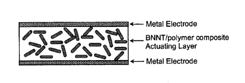
[16] Figure 1 a shows a schematic diagram of a metal electroded BNNT/polyrner
composite actuator;
[17] Figure lb shows a Schematic diagram of a carbon nanotube electroded BNNT
actuator;
[18] Figure 2a shows a graph of thermally stimulated current (TSC) spectra of
pristine
polyimide and 2wt% BNNT/polyimide composite;
[19] Figure 2b shows a graph of remanent polarization (Pr) of pristine
polyimide and
2wt% BNNT/polyimide composite;
[20] Figure 3 shows a proto-type BNNT actuator fabricated with carbon nanotube

electrodes;
[21] Figure 4 shows a cross-sectional SEM image of a prototype BNNT actuator
fabricated with carbon nanotube electrodes;
[22] Figure 5a shows 'a graph of the electric field induced strain of the BNNT
actuator
fabricated with CNT electrodes;
6

CA 02777666 2012-04-13
WO 2011/046602 PCT/US2010/002737
[23] Figure 5b shows a graph of the piezoelectric response of the BNNT
actuator
fabricated with CNT electrodes; and
[24] Figure 5c shows a graph of the electrostrictive response of the BNNT
actuator
fabricated with CNT electrodes.
DETAILED DESCRIPTION OF THE PREFERRED EMBODIMENT
[25] The following detailed description is of the best presently contemplated
mode of
carrying out the invention. This description is not to be taken in a limiting
sense, but is made
merely for the purpose of illustrating general principles of embodiments of
the invention.
[26] Since the first theoretical prediction of the existence of boron
nitride nanotubes
(BNNTs) in 1994 and the first experimentally synthesized BNNT report by
Zettl's group in
1995, several types of BNNT synthesis methods have been reported. Recently, a
new and
conceptually simple method of producing extraordinarily long, highly
crystalline BNNTs was
demonstrated. BNNTs are thought to possess high strength-to-weight ratio, high
thermal
stability (up to about 800 C in air), piezoelectricity, and radiation
shielding capabilities.
Nalchmanson's theoretical analysis predicted that the piezoelectric
coefficient of BNNTs can be
higher than that of poly(vinylidene fluoride) (PVDF) or poly(vinylidene
fluoride-
trifluoroethyene) P(VDF-TrFE). However, the piezoelectric properties of BNNTs
or BNNT
composites have not been reported experimentally as yet. In this invention, we
make use of the
electroactive characteristics of novel BNNT based materials.
7

CA 02777666 2012-04-13
WO 2011/046602 PCT/US2010/002737
[27] First, a BNNT/polyimide nanocomposite film was synthesized as an
electroactive
layer by in-situ polymerization under simultaneous shear and sonication. The
high temperature
piezoelectric polyimide, used as a matrix for this invention, was synthesized
from a diarnine, 2,6-
bis(3-aminophenoxy) benzonitrile ((13-CN)APB), and a dianhydride, pyromellitic
dianhydride
(PMDA). The concentrations of BNNTs in the polyimide were 0 and 2 wt%. In
order to
characterize electroactive properties of the composites, the samples were
coated with metal
(chrome/gold) electrodes for both sides (FIG la).
[28] Thermally stimulated current (TSC) spectra of the BNNT nanocomposites
were
obtained using a Setaram TSC II. Each sample was polarized by a direct current
(DC) electric
field of 5 MV/m at an elevated temperature (Tp = Tg¨ 5 C) for a selected
poling time (tp = 30
min). The glass transition temperatures (Tg) of the pristine polyimide and 2%
BNNT/polyimide
composite, measured by a differential scanning calorimeter (DSC), are 274.3
and 271.4 C,
respectively. After poling, the depolarization current was measured as the
sample was heated
through its glass transition temperature (Tg) at a heating rate of 7.0 C/min.
As shown in Figure
2a, the pristine polyimide showed negligible depolarization currents until
about 225 C, which
indicates a good thermal stability of polarization, and then exhibited a rapid
depolarization
current with a maximum peak of 0.012mA/m2 at 255.9 C. On the other hand, the
2wt%
BNNT/polyimide nanocomposite exhibited two depolarization peaks at 119.3 C and
255.5 C.
The magnitude of the depolarization current of the nanocomposite was
significantly larger than
that of the pristine polyimide as seen in FIG 2b, and reached a maximum value
of about 0.05
inA/m2, five times greater than that of the pristine polyimide. The remanent
polarization (Pr) was
8

CA 02777666 2012-04-13
WO 2011/046602 PCT/US2010/002737
calculated by integrating the current with respect to time and is plotted as a
function of
temperature as shown in FIG 2b. Pr is given by,
P, ¨q= ¨1 I I(t)dt (1)
A A
where q is the charge, A is the electrode area, I is the current, and t is the
time. Details of
conventional poling procedures have been described elsewhere [J. H. Kang et
al., NANO, 1, 77
(2006)]. The remanent polarization (Pr) of the 2wt% BNNT/polyimide
nanocomposite was 12.20
mC/m2, almost an order of magnitude higher than that of the pristine polyimide
(1.87 mC/m2). In
general, the piezoelectricity of a material is proportional to its remanent
polarization. From the
TSC result, adding BNNT, even only 2wtc/0, was proven to increase the
piezoelectricity
(remanent polarization) of the polyimide significantly.
1291 An all nanotube film actuator, with a BNNT active layer, was fabricated
by a
filtering method [J. H. Kang et al., J. Polym. Sci. B: Polym Phys. 46, 2532
(2008)]. Single wall
carbon nanotubes (SWCNTs) were used as electrodes for the actuator instead of
metal. First,
solutions of SWCNTs and BNNTs were prepared in N-methylpyrrolidone (NMP) under

sonication. An adequate amount of the SWCNT solution was filtered through the
surface of an
anodized alumina membrane (pore size: 0.2 pm) to form a SWCNT film on the
membrane.
Then, the BNNT solution and finally the SWCNT solution were sequentially
filtered onto the
9

CA 02777666 2012-04-13
WO 2011/046602 PCT/US2010/002737
SWCNTs film on the membrane to make a three layered (SWCNT/BNNT/SWCNT) "all-
nanotube actuator" structure shown in FIG 3. The freestanding all-nanotube
actuator film,
shown in FIG 3, was easily delarninated by breaking the brittle membrane. To
increase
durability, polyurethane resin was infused into the all-nanotube actuator. FIG
4 shows the cross-
sectional scanning electron microscopy (SEM) image of a prototype BNNT
actuator fabricated
with SWCNT electrodes (Hitachi S-5200 Field Emission Scanning Electron
Microscope). The
top and bottom layers are SWCNT electrodes and the middle layer is the BNNT
actuating layer.
PO] In-plane strain (SB) was measured using a fiber optic device while
the sample was
under an alternating current (AC) electric field of 1 Hz. The strain (SB) of
the sample appears as
a superposed curve (black solid squares in FIG 5a) of linear and nonlinear
strains as a function of
frequency. The superposed curve was de-convoluted to a linear response (red
solid circles in FIG
5a) and a nonlinear response (blue solid triangles in FIG 5a). The linear
response seems to
originate from the piezoelectric property of the BNNT active layer. From
linear fitting of the data
(FIG 5b), the piezoelectric coefficient, c/13 was calculated to be about 14.80
pm/V. This is
comparable to the values of commercially available piezoelectric polymers such
as
poly(vinylidene fluoride) (PVDF). The nonlinear response showed a quadratic
increase with
increasing applied electric field, indicating that the mechanism of this
strain is mainly an
electrostrictive response (FIG 5c). The electrostrictive coefficient (Mn) of
the BNNT active
layer, calculated from the slope of a plot of the strain (SB) to the square of
electric field strength
(E2), S13 = M13 E2, was 3.21 x 10⁻¹⁶ pm2N2 on average. This value is several
orders of magnitude
higher than those of electrostrictive polyurethanes (-4.6 x 10⁻¹⁸ to ¨7.5 x
1047 m2/V2).

WO 2011/046602 PCT/US2010/002737
[31] Obviously, many modifications may be made without departing from
the basic
spirit of the present invention. Accordingly, it will be appreciated by those
skilled in the art that
within the scope of the appended claims, the invention may be practiced other
than has been
specifically described herein. Many improvements, modifications, and additions
will be
apparent to the skilled artisan without departing from the spirit and scope.
11
CA 2777666 2019-12-18

Representative Drawing
A single figure which represents the drawing illustrating the invention.
Administrative Status

For a clearer understanding of the status of the application/patent presented on this page, the site Disclaimer , as well as the definitions for Patent , Administrative Status , Maintenance Fee  and Payment History  should be consulted.

Administrative Status

Title Date
Forecasted Issue Date 2021-01-05
(86) PCT Filing Date 2010-10-13
(87) PCT Publication Date 2011-04-21
(85) National Entry 2012-04-13
Examination Requested 2015-10-08
(45) Issued 2021-01-05

Abandonment History

There is no abandonment history.

Maintenance Fee

Last Payment of $263.14 was received on 2023-10-06


 Upcoming maintenance fee amounts

Description Date Amount
Next Payment if standard fee 2024-10-15 $347.00
Next Payment if small entity fee 2024-10-15 $125.00

Note : If the full payment has not been received on or before the date indicated, a further fee may be required which may be one of the following

  • the reinstatement fee;
  • the late payment fee; or
  • additional fee to reverse deemed expiry.

Patent fees are adjusted on the 1st of January every year. The amounts above are the current amounts if received by December 31 of the current year.
Please refer to the CIPO Patent Fees web page to see all current fee amounts.

Payment History

Fee Type Anniversary Year Due Date Amount Paid Paid Date
Application Fee $400.00 2012-04-13
Maintenance Fee - Application - New Act 2 2012-10-15 $100.00 2012-04-13
Maintenance Fee - Application - New Act 3 2013-10-15 $100.00 2013-10-10
Maintenance Fee - Application - New Act 4 2014-10-14 $100.00 2014-10-10
Request for Examination $800.00 2015-10-08
Maintenance Fee - Application - New Act 5 2015-10-13 $200.00 2015-10-08
Maintenance Fee - Application - New Act 6 2016-10-13 $200.00 2016-10-12
Maintenance Fee - Application - New Act 7 2017-10-13 $200.00 2017-09-21
Maintenance Fee - Application - New Act 8 2018-10-15 $200.00 2018-07-24
Maintenance Fee - Application - New Act 9 2019-10-15 $200.00 2019-08-06
Maintenance Fee - Application - New Act 10 2020-10-13 $250.00 2020-10-09
Final Fee 2020-11-13 $300.00 2020-10-29
Correction of an error under subsection 109(1) 2021-02-05 $204.00 2021-02-05
Maintenance Fee - Patent - New Act 11 2021-10-13 $255.00 2021-10-11
Maintenance Fee - Patent - New Act 12 2022-10-13 $254.49 2022-10-07
Maintenance Fee - Patent - New Act 13 2023-10-13 $263.14 2023-10-06
Owners on Record

Note: Records showing the ownership history in alphabetical order.

Current Owners on Record
NATIONAL INSTITUTE OF AEROSPACE ASSOCIATES
UNITED STATES OF AMERICA AS REPRESENTED BY THE ADMINISTRATOR OF THE NATIONAL AERONAUTICS AND SPACE ADMINISTRATION
Past Owners on Record
None
Past Owners that do not appear in the "Owners on Record" listing will appear in other documentation within the application.
Documents

To view selected files, please enter reCAPTCHA code :


To view images, click a link in the Document Description column. To download the documents, select one or more checkboxes in the first column and then click the "Download Selected in PDF format (Zip Archive)" or the "Download Selected as Single PDF" button.

List of published and non-published patent-specific documents on the CPD .

If you have any difficulty accessing content, you can call the Client Service Centre at 1-866-997-1936 or send them an e-mail at CIPO Client Service Centre.


Document
Description 
Date
(yyyy-mm-dd) 
Number of pages   Size of Image (KB) 
Amendment 2019-12-18 16 500
Description 2019-12-18 11 337
Claims 2019-12-18 8 259
Final Fee 2020-10-29 4 140
Representative Drawing 2020-12-07 1 11
Cover Page 2020-12-07 2 51
Patent Correction Requested 2021-02-05 5 167
Cover Page 2021-02-12 3 265
Correction Certificate 2021-02-12 2 462
Abstract 2012-04-13 1 77
Claims 2012-04-13 4 71
Drawings 2012-04-13 5 190
Description 2012-04-13 11 376
Representative Drawing 2012-04-13 1 9
Cover Page 2012-06-21 2 50
Amendment 2019-03-14 12 496
Examiner Requisition 2017-09-25 6 334
Amendment 2018-03-26 12 430
Description 2018-03-26 11 349
Claims 2018-03-26 3 111
Drawings 2018-03-26 5 196
Examiner Requisition 2018-09-14 6 394
Description 2019-03-14 11 349
Claims 2019-03-14 7 290
PCT 2012-04-13 7 407
Assignment 2012-04-13 4 116
Correspondence 2012-04-13 1 63
Correspondence 2012-04-24 2 81
Examiner Requisition 2019-06-25 5 278
Fees 2014-10-10 1 33
Fees 2015-10-08 1 33
Request for Examination 2015-10-08 2 58
Examiner Requisition 2016-10-24 5 225
Amendment 2017-04-24 10 334
Claims 2017-04-24 3 95
Description 2017-04-24 11 350