Note: Descriptions are shown in the official language in which they were submitted.
CA 02777756 2012-04-13
WO 2011/050094 PCT/US2010/053420
STEAM DISTRIBUTION AND CONDITIONING ASSEMBLY
FOR ENHANCED OIL RECOVERY OF VISCOUS OIL
CROSS-REFERENCE TO RELATED APPLICATIONS
[0001] The present application for patent claims the benefit of United States
Provisional Application bearing Serial No. 61/254,144, filed on October 22,
2009,
which is incorporated by reference in its entirety.
BACKGROUND
1. Field of the Invention
[0002] This invention relates to oil field production apparatus and
techniques,
and more particularly, to such apparatus and techniques for use in the
production of
heavy oil or viscous crude oil.
2. Background of the Invention
[0003] It has been known to produce viscous crude oils in reservoirs by
drilling vertical wells into the producing zone and then injecting steam into
the
producing zone to increase the mobility and reduce the viscosity of the
viscous crude.
This steam injection has been done in several different ways. In one
technique, wells
in the reservoir can be cyclically steamed using a process called cyclic steam
stimulation (CSS). In this process, steam is injected down a vertical well
into the
producing zone. The steam is allowed to "soak" in the reservoir for a
relatively short
period of time to heat the crude oils, thus reducing its viscosity and
increasing its
mobility. The well is then placed back in production for a relatively longer
period of
time to extract the heated less viscous crude oil. This cycle is typically
repeated until
the production becomes unprofitable.
-1-
CA 02777756 2012-04-13
WO 2011/050094 PCT/US2010/053420
[0004] Another technique which has been used to produce viscous crude
reservoirs is to drill vertical wells in a geometrical pattern into the
producing zone,
such as in a 5-spot or 9-spot pattern. In these geometrical patterns, the
wells are
placed within the reservoir field, typically in a symmetric fashion, and are
designated
as either an injection well or a production well based on its position in the
pattern.
Steam is continuously injected into the producing zone via the injection wells
in an
attempt to heat the viscous crude oil and drive it to neighboring vertical
producing
wells in the geometrical array.
[0005] In the initial development of a reservoir of viscous crude these
described methods have worked well. Over time however, the steam tends to
congregate in the upper portion of the producing zone. This, of course, may
cause less
heating of the viscous crude in the lower portion of the producing zone. The
heavy
crude saturated lower portion of the producing zone is not depleted as the
high
viscosity of the crude prevents its migration to the well bores of the
producing wells.
Thus large quantities of potentially producible crude oil can otherwise become
not
recoverable.
[0006] It is known in the art that horizontally-oriented, or horizontal wells
can
be utilized to help production from the portions of the producing zone,
especially the
lower portion discussed above, which are typically not depleted after
injecting steam
with vertical wells. It is desirous in these assemblies to deliver uniformly
distributed
steam to the producing zone along the entire length of the horizontal section
of the
well.
-2-
CA 02777756 2012-04-13
WO 2011/050094 PCT/US2010/053420
[0007] Horizontal steam injection wells are becoming more functional and
efficient for heavy oil steam flooding and in many cases the only economic
solution to
produce some reservoirs. Successful application of horizontal steam injection
requires controlled steam distribution along the entire length of the
horizontal section.
Many devices have been promoted as completion methods to provide this
controlled
distribution; however, these devices have not been tested and have severe
limitations.
[0008] The main limitation is that the proposed equipment can at best provide
control for the injection of single phase steam ("100% quality"). The
performance of
such devices when extracting a portion of a wet steam flow, vapor and liquid,
suffers
from phase splitting effects. This phase splitting phenomenon relates to the
fact that
the percent of vapor extracted from the total vapor is different than the
percent liquid
extracted from the total liquid. For example, if the main flow has a steam
quality of
seventy-percent (70%), the extracted flow may have a significantly higher or
lower
quality.
[0009] Many steam flood operations use two-phase steam consisting of both a
vapor and a liquid phase. Even for operations injecting single phase, 100%
quality
steam at the wellhead, heat losses and water holdup can yield varying steam
qualities
along the subsurface horizontal section. Furthermore, if both phases do not
split
proportionally within a device, mass distribution is non-uniform and uniform
latent
heat - a more crucial reservoir performance criteria - is not achieved.
[0010] Most proposed devices extract steam off the main tubing flow through
a series of orifices which may or may not feed additional flow restricting
mechanisms
before delivery to the reservoir. The basis for many of these devices and
hopes for
-3-
CA 02777756 2012-04-13
WO 2011/050094 PCT/US2010/053420
success rely on modified Inflow Control Devices ("ICDs") operating in a
reversed
flow direction ("injection mode"). Although not fully tested, such mechanisms
do
have potential for the distribution of single phase, 100% quality steam.
However, in
applications utilizing two-phase steam, flow regime effects and different
phase
velocities cause unknown phase distributions depending on the vapor-water
separation within the device. Optimum steam distribution and latent heat
delivery
requires a device capable of reliably controlling injected steam over a range
of
qualities of about forty percent (40%) to one-hundred percent (100%).
SUMMARY
[0011] According to an aspect of the present invention, a well assembly is
disclosed for injecting steam into a subterranean reservoir. The well assembly
includes a string of tubing in fluid communication with a producing zone of a
subterranean reservoir. The string of tubing has a substantially vertical
section and a
substantially horizontal section extending from a lower portion thereof. The
substantially horizontal section defines a heel portion at one end and a toe
portion at
the opposite end. An opening formed on the inner surface of the substantially
horizontal section defines an inlet. An opening formed on the outer surface of
the
substantially horizontal section defines an outlet. A passageway extends
between the
inlet and the outlet such that steam received by the inlet is delivered to the
outlet. A
flow conditioning device is positioned in the string of tubing axially closer
to the heel
portion than the inlet to generate a more homogenous mixture of the vapor and
liquid
components of the two-phase steam.
-4-
CA 02777756 2012-04-13
WO 2011/050094 PCT/US2010/053420
[0012] In one or more embodiments, the flow conditioning device is a stator.
In one or more embodiments, the flow conditioning device is a plurality of
axially
spaced stators, which define a conditioning region. In one or more
embodiments, the
flow conditioning device includes a plurality of vanes extending inwardly from
the
inner surface of the string of tubing and around the circumference thereof.
[0013] In one or more embodiments, the flow conditioning device is adapted
to allow a logging tool to travel therethrough.
[0014] In one or more embodiments, the flow conditioning device is
positioned in the string of tubing a length between about four to six times
the diameter
of the string of tubing upstream of the inlet.
[0015] In one or more embodiments, the flow conditioning device is carried
within the string of tubing. In one or more embodiments, the flow conditioning
device is positioned between segments of tubing within the substantially
horizontal
section of the string of tubing.
[0016] In one or more embodiments, the string of tubing has a reduced
cross-sectional flow area and the inlet is formed in the reduced cross-
sectional flow
area. For example, the reduced cross-sectional flow area can have an inwardly
tapered surface and the inlet can be formed at least partially on the inwardly
tapered
surface.
[0017] In one or more embodiments, the inlet is formed in the string of tubing
axially closer to the heel portion than the outlet so that when steam is
received by the
-5-
CA 02777756 2012-04-13
WO 2011/050094 PCT/US2010/053420
passageway an axial momentum of the steam is maintained. For example, the
passageway can extend less than about fifteen degrees from the inner surface.
[0018] In one or more embodiments, an annulus that is in fluid
communication with the outlet is formed in the outer surface of the string of
tubing
and extends around the circumference thereof. A nozzle can be positioned
within the
annulus to control the flow of steam received from the outlet.
[0019] Another aspect of the present invention includes a well assembly for
injecting steam into a subterranean reservoir. The well assembly includes a
string of
tubing in fluid communication with a producing zone of a subterranean
reservoir. The
string of tubing has a substantially vertical section and a substantially
horizontal
section extending from a lower portion thereof. The substantially horizontal
section
defines a heel portion at one end and a toe portion at the opposite end. An
opening
formed on the inner surface of the substantially horizontal section defines an
inlet.
An opening formed on the outer surface of the substantially horizontal section
defines
an outlet. A passageway extends between the inlet and the outlet such that
steam
received by the inlet is delivered to the outlet. A flow conditioning device
is
positioned in the string of tubing axially closer to the heel portion than the
inlet. The
flow conditioner has a plurality of vanes extending inwardly from the inner
surface of
the string of tubing and around the circumference thereof so that when steam
is
received by the plurality of vanes a more homogenous mixture of vapor and
liquid
components of the steam is generated.
-6-
CA 02777756 2012-04-13
WO 2011/050094 PCT/US2010/053420
[0020] In one or more embodiments, the plurality of vanes extending inwardly
from the inner surface of the string of tubing are axially spaced to define a
conditioning region.
[0021] In one or more embodiments, the plurality of vanes extending inwardly
from the inner surface of the string of tubing provide sufficient clearance to
allow a
logging tool to travel therethrough.
[0022] In one or more embodiments, the flow conditioning device is
positioned in the string of tubing a length between about four to six times
the diameter
of the string of tubing upstream of the inlet.
[0023] In one or more embodiments, the flow conditioning device is carried
within the string of tubing. In one or more embodiments, the flow conditioning
device is positioned between segments of tubing within the substantially
horizontal
section of the string of tubing.
[0024] In one or more embodiments, the string of tubing has a reduced
cross-sectional flow area and the inlet is formed in the reduced cross-
sectional flow
area. For example, the reduced cross-sectional flow area can have an inwardly
tapered surface and the inlet can be formed at least partially on the inwardly
tapered
surface.
[0025] In one or more embodiments, the inlet is formed in the string of tubing
axially closer to the heel portion than the outlet so that when steam is
received by the
passageway an axial momentum of the steam is maintained. For example, the
passageway can extend less than about fifteen degrees from the inner surface.
-7-
CA 02777756 2012-04-13
WO 2011/050094 PCT/US2010/053420
[0026] In one or more embodiments, an annulus that is in fluid
communication with the outlet is formed in the outer surface of the string of
tubing
and extends around the circumference thereof. A nozzle can be positioned
within the
annulus to control the flow of steam received from the outlet.
BRIEF DESCRIPTION OF THE DRAWINGS
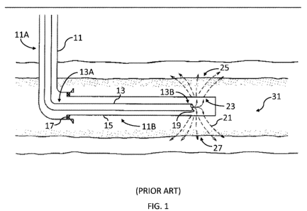
[0027] Figure 1 is a schematic, sectional view of a prior art steam delivery
in a
horizontal well in the field of hydrocarbon production.
[0028] Figure 2 is a schematic, sectional view of a prior art steam delivery
in a
horizontal well in the field of hydrocarbon production.
[0029] Figure 3 is a schematic, sectional view of a prior art tubing string
distribution assembly for use in a horizontal well in the field of hydrocarbon
production.
[0030] Figure 4 is a schematic, sectional view of a tubing string distribution
assembly according to an embodiment of the present invention for use in a
horizontal
well in the field of hydrocarbon production.
[0031] Figure 5 is a schematic, sectional view of a tubing string distribution
assembly according to an embodiment of the present invention for use in a
horizontal
well in the field of hydrocarbon production.
[0032] Figure 6 is a schematic, sectional view of a tubing string distribution
assembly according to an embodiment of the present invention for use in a
horizontal
well in the field of hydrocarbon production.
-8-
CA 02777756 2012-04-13
WO 2011/050094 PCT/US2010/053420
[0033] Figure 7 is a schematic, sectional view of a tubing string distribution
assembly according to an embodiment of the present invention for use in a
horizontal
well in the field of hydrocarbon production.
[0034] Figure 8 is a schematic, sectional view of a tubing string distribution
assembly according to an embodiment of the present invention for use in a
horizontal
well in the field of hydrocarbon production.
[0035] Figure 9 is a schematic, sectional view of a flow conditioner according
to an embodiment of the present invention for use in a horizontal well in the
field of
hydrocarbon production.
[0036] Figure 10 is a schematic, section view of the flow conditioner of
Figure 9 engaging a tubing string steam distribution assembly.
[0037] Figure 11 is a graph of steam phase splitting for a conventional tubing
string distribution assembly for use in a horizontal well in the field of
hydrocarbon
production.
[0038] Figure 12 is a graph of steam phase splitting for a tubing string
distribution assembly according to an embodiment of the present invention for
use in
a horizontal well in the field of hydrocarbon production.
DETAILED DESCRIPTION
[0039] Referring initially to prior art Figure 1, a cross sectional view shows
a
wellbore 11 having vertical section 11A and horizontal section 11B. Wellbore
11
provides a flow path between the well surface and producing sand or reservoir
31.
-9-
CA 02777756 2012-04-13
WO 2011/050094 PCT/US2010/053420
Tubing string 13 and slotted liner 15 are also shown in Figure 1. The
horizontal
section 11B of tubing string 13 includes a heel portion 13A and an opposite
toe
portion 13B. Slotted liner 15 is a completion device lining horizontal section
1lB of
wellbore 11 and is typically isolated by a lead seal 17 from vertical section
11A of
wellbore 11. Live steam is supplied via tubing string 13 and exits from toe
portion 13B at end 19. The steam flow is as indicated by arrows 21. Direct
impingement of live steam onto slotted liner 15 at the area numbered 23 can
potentially cause erosion and collapse of the liner 15, which is an
undesirable
condition. Also, using this technique the steams' heat is concentrated near
toe
portion 13B in areas 25 and 27 of reservoir 31 rather than along the length of
slotted
liner 15.
[0040] Referring now to prior art Figure 2, wellbore 29 has vertical
section 29A, which goes to the surface, and horizontal section 29B that
penetrates a
long horizontal section of producing sand or reservoir 31. Slotted liner 37
lines
horizontal section 29B of wellbore 29. Tubing string 33 is run in from the
surface
and, on the lower end thereof is plugged off by plug 35. The horizontal
section 29B
of tubing string 33 includes a heel portion 33A and an opposite toe portion
33B. The
length of tubing string 33, prior to the plug 35, is provided with spaced
apart drilled
holes 39 along its entire horizontal section between heel portion 33A and toe
portion 33B. Each drilled hole 39 is covered with a sacrificial impingement
strap 41.
Sacrificial impingement straps 41 are constructed of a carbon steel material
and may
be ceramic coated if desired. Sacrificial impingement straps 41 are welded to
tubing
string 33 with an offset above each drilled hole 39.
-10-
CA 02777756 2012-04-13
WO 2011/050094 PCT/US2010/053420
[0041] A steam generator source (not shown) is located at the surface and
provides an input of steam into tubing string 33. The steam travels down
tubing
string 33 to its lower horizontal section 29B where it exits via drilled holes
39. As
will be described, while steam can exit tubing string 33 between heel portion
33A and
toe portion 33B, uniform mass distribution and latent heat is not achieved
along
horizontal section 29B.
[0042] Referring to Figure 3, a cross-section of a portion of tubing string 33
that is located within slotted liner 37 of Figure 2 is shown. Sacrificial
impingement
straps 41 are not shown in Figure 3. Tubing string 33 includes inner surface
43 and
outer surface 45. A plurality of drilled holes 39 extend from inner surface 43
to outer
surface 45. Each drilled hole 39 extends radially outward, substantially
perpendicular
to inner surface 43. Typically, drilled holes 39 are intermittently spaced
between heel
portion 33A and toe portion 33B of tubing sting 33 for delivering steam to
reservoir 31. A two-phase fluid F, typically steam having vaporous water and
liquid
water droplets D, travel through tubing string 33 for delivery into oil sands
or
reservoir 31.
[0043] When two-phase fluid F is under low velocity conditions, such as less
than 40 feet per second, the flow is stratified. In particular, gravity causes
the liquid
phase to travel along the bottom portion of the pipe. When superficial vapor
and
liquid velocities are both low, the interface between the liquid and vapor
phases is
smooth. As vapor velocities begin to increase, the interface becomes wavy. As
the
superficial liquid velocities increase, the flow tends to form in slugs or
large waves of
liquid (short in duration) separated by stratified wavy flow. At very high
superficial
-11-
CA 02777756 2012-04-13
WO 2011/050094 PCT/US2010/053420
flow velocities, the liquid forms a ring on the inner surface of the pipe wall
and the
vapor travels in the center of the pipe. At high superficial vapor velocities
and steam
qualities, the liquid becomes entrained in the vapor core such that the pipe
is filled
with vapor except for small droplets of liquid mist.
[0044] Liquid droplets D have higher densities and thus higher momentum
than the vaporous water, which restricts the ability of liquid droplets D to
change
direction. When liquid droplets D traveling in the main flow of fluid F
encounter a
smaller vapor flow, or velocity profile, toward drilled holes 39, liquid
droplets D
experience a drag force to change direction. However, the momentum of liquid
droplets D opposes this change of direction, thereby resulting in less
movement
toward drilled holes 39. In the embodiment shown in Figure 3, the liquid
droplets
entrained in the vapor core must make sharp, radially outward turns with
respect to
the flow of fluid F for liquid droplets to enter drilled holes 39 for delivery
into
reservoir 31. This results in the extracted steam having less liquid droplets
D such
that the quality of the steam delivered at the upstream portion of tubing
string 33 is
different from the steam delivered to the downstream portion of tubing string
33. In
particular, more liquid droplets will be delivered toward the downstream toe
portion 33A of tubing string 33 than to heel portion 33B. Such a phenomenon is
known as "phase splitting."
[0045] In Figures 4-8, alternative tubing configurations are provided to
counteract the phase splitting described above so that more uniform quality
steam is
delivered to reservoir 31 from both the upstream and downstream portions of
the
respective tubing strings. More particularly, Figures 4-8 each show a portion
of
-12-
CA 02777756 2012-04-13
WO 2011/050094 PCT/US2010/053420
tubing sub or string of tubing 111 disposed between the heel portion and the
toe
portion of the horizontal section of a wellbore. As will be described, steam
generated
at the surface is delivered to tubing 111 for a more uniform steam quality
distribution
along the horizontal section of a wellbore into reservoir 31.
[0046] Referring to Figure 4, tubing 111 includes a plurality of openings 117
extending from inner surface 113 to outer surface 115. Openings 117 include an
opening formed on inner surface 113 that defines inlet 117A, an opening formed
on
outer surface 115 that defines outlet 117B, and passageway 117C extending
between
inlet 117A and outlet 117B such that steam received by inlet 117A is delivered
to
outlet 117B. Inlet 117A is formed in the string of tubing axially closer to
the heel
portion than outlet 117B. While openings 117 are illustrated as having about
fifteen
degree outward angles to the flow of fluid F, it should be understood that the
optimum
angle for openings 117 is the smallest angle allowed by machining tools.
[0047] A plurality of openings 117 are preferably intermittently spaced along
the length of tubing 111. For example, openings 117 can be positioned every
100 to
500 feet along tubing 111. In general, spacing of openings 117 will be
dependent
upon the particular reservoir characteristics. One skilled in the art will
appreciate that
isolation between a first group of openings 117 and a second group of openings
117
can be utilized. Furthermore, conventional sand control mechanisms, such as a
sand
screen, can be placed adjacent to openings 117. In one embodiment, tubing 111
ends
near the heel portion and openings 117 are configured in the liner.
[0048] Openings 117 reduce the directional change necessary for liquid
droplets to enter openings 117, thereby making it easier for liquid droplets
to exit
-13-
CA 02777756 2012-04-13
WO 2011/050094 PCT/US2010/053420
tubing 111. In particular, when steam is received by passageway 117C an axial
momentum of the steam is maintained. Accordingly, the difference in steam
quality
delivered from the upstream portion of tubing 111 compared with the downstream
portion of tubing 111 is reduced as more liquid droplets entrained in the
vapor core
are able to exit openings 117.
[0049] Referring to Figure 5, an alternative tubing configuration is provided
to
counteract the segregation of vapor and liquid in Fluid F so that more uniform
quality
steam is delivered to reservoir 31 from both the upstream and downstream
portions of
the respective tubing strings. As shown in Figure 5, tubing 111 includes
mandrel
portion or tubing sub 120 with a reduced cross-sectional flow area and a
plurality of
openings 117 extending from inner surface 113 to outer surface 115. Openings
117
include an opening formed on inner surface 113 that defines inlet 117A, an
opening
formed on outer surface 115 that defines outlet 117B, and passageway 117C
extending between inlet 117A and outlet 117B such that steam received by inlet
117A
is delivered to outlet 117B. Inlet 117A and outlet 117B are formed at
substantially
the same axial locations between the heel and the toe of the string of tubing.
As with
the embodiment in Figure 4, a plurality of openings 117 are preferably
intermittently
spaced along the length of tubing 111, with each opening 117 being associated
with a
tubing sub 120.
[0050] Tubing sub 120 includes inwardly tapered surface 121 that extends
between the portion of inner surface 113 having the normal diameter of tubing
111
and reduced diameter surface 123, which is where openings 117 are located.
Inwardly tapered surface 121 is located upstream of openings 117 to condition
the
-14-
CA 02777756 2012-04-13
WO 2011/050094 PCT/US2010/053420
flow of fluid F. Tubing sub 120 can also include outwardly tapered surface 125
that
is positioned downstream of openings 117, and that extends from reduced
diameter
surface 123 to the portion of inner surface 113 having the normal diameter of
tubing 111.
[0051] The reduction in the diameter of tubing 111 at inwardly tapered
surface 121 increases the velocity of fluid F, while the increase in diameter
from
outwardly tapered surface 125 reduces the velocity of fluid F. The continued
variation of the velocity of fluid F along the length of tubing 111 induces
mixing of
liquid droplets D with the vaporous water prior to flowing toward openings
117.
Mixing fluid F can help provide a more uniform steam quality being delivered
along
the length of tubing 111. By way of example, if tubing 111 were a conventional
string of 4.5 inch tubing, inner diameter 113 would be about 3.96 inches. The
desired
velocity change could be achieved when reduced diameter surface 123 is
equivalent to
the inner diameter of standard 2 3/8 inch tubing, which is about 2.44 inches.
Preferably inwardly and outwardly tapered surfaces 121, 125 are at about
fifteen
degree respective inclines or declines.
[0052] Referring to Figure 6, an alternative tubing configuration is shown
where tubing 111 includes openings 117 extending at an angle from inner
surface 113
to outer surface 115. Openings 117 include an opening formed on inner surface
113
that defines inlet 117A, an opening formed on outer surface 115 that defines
outlet 117B, and passageway 117C extending between inlet 117A and outlet 117B
such that steam received by inlet 117A is delivered to outlet 117B. Inlet 117A
is
formed in the string of tubing axially closer to the heel portion than outlet
117B.
-15-
CA 02777756 2012-04-13
WO 2011/050094 PCT/US2010/053420
[0053] In the embodiment, the diameter of inner surface 113 adjacent
openings 117 is reduced, thereby making the thickness of tubing 111
immediately
upstream and downstream of openings 117 thicker than in the embodiment shown
in
Figure 4. Similar to Figure 5, tubing sub 120 includes inwardly extending
tapered
surface 121 that extends between the portion of inner surface 113 having the
normal
diameter of tubing 111 and reduced diameter surface 123, which is where
openings 117 are located. Inwardly tapered surface 121 is located upstream of
openings 117 to condition the flow of fluid F. Outwardly tapered surface 125
is
positioned downstream of openings 117 and extends from reduced diameter
surface 123 to the portion of inner surface 113 having the normal diameter of
tubing 111.
[0054] Tubing sub 120 in Figure 7 is substantially the same as in Figures 5
and 6 except that openings 117 extend axially through tubing 111 from inwardly
tapered surface 121. Openings 117 include an opening formed on inner surface
113
that defines inlet 117A, an opening formed on outer surface 115 that defines
outlet
117B, and passageway 117C extending between inlet 117A and outlet 117B such
that
steam received by inlet 117A is delivered to outlet 117B. Inlet 117A is formed
in the
string of tubing axially closer to the heel portion than outlet 117B.
Preferably,
openings 117 are as close to parallel with the axial flow of fluid F as
possible with
machining capabilities. Locating openings 117 on inwardly tapered surface 121
allows liquid droplets to enter outlets 117 with minimal deviation from the
path of
liquid droplets D prior to encountering reduced diameter surface 123. For
example,
-16-
CA 02777756 2012-04-13
WO 2011/050094 PCT/US2010/053420
the inwardly tapered surface 121 can be tapered about fifteen degrees from an
axis of
the tubing 111 and the inlet can be about parallel to the axis of the tubing
111.
[0055] As shown in Figure 7, openings 117 extend axially to an annulus 129
formed radially outward of reduced diameter surface 123. In particular,
annulus 129
is formed in the outer surface 115 of the string of tubing and extends around
the
circumference thereof. However, in some embodiments annulus 129 is not present
and openings 117 axially extend between inwardly tapered surface 121 and outer
surface 115.
[0056] The embodiment shown in Figure 8 is substantially the same as
Figure 7 except that nozzles 131 are positioned in annulus 129 to receive
fluid from
openings 117. Nozzles 131 can be sized to more precisely control the rate of
steam
delivery into reservoir 31 from each opening 117 along tubing 111. Examples of
nozzles 131 include an orifice with a reduced cross-section or a venturi.
Additionally,
because nozzles 131 are controlling the rate of steam delivery in this
embodiment,
openings 117 can be enlarged to enhance liquid droplet D capture to a
predetermined
amount.
[0057] As will be readily understood by those skilled in the art, tubing 111
for
each of the embodiments shown in Figures 4-8 can be a tubing sub that is
positioned
between pairs of tubing rather than being integrated in the string of tubing
itself. This
type of delivery can prevent steam migration into the underlying water zone or
into
the upper desaturated portion of the reservoir. Also by delivering the steam
uniformly
along the entire horizontal portion of the producing zone penetrated by the
horizontal
portion of the well, any potential damage to a production liner in this
horizontal bore
-17-
CA 02777756 2012-04-13
WO 2011/050094 PCT/US2010/053420
is reduced. Furthermore, the above embodiments reduce phase splitting along
the
horizontal portion of the wellbore, thus delivering a uniform steam quality
and
ensuring uniform latent heat to the reservoir.
[0058] Referring to Figure 9, a flow conditioner or conditioning sub 133
includes a conditioner housing 135 that is substantially tubular. Frusto-
conical end
pieces 137,139 are positioned at each end of housing 135 with an opening 141
being
formed at upstream end piece 137 and an opening 143 being formed at downstream
end piece 139. End pieces 137,139 are tapered such that openings 141, 143 have
a
smaller diameter than housing 135.
[0059] Carried within housing 135 is a conditioning mechanism 145
extending coaxially with housing 135. Conditioning mechanism 145 includes a
plurality of inwardly extending vanes or stators 147 that are intermittently
spaced
around the inner circumference of conditioning mechanism 145. Stators 147
typically
extend axially downstream, and provide enough clearance between their
respective
radially inward tips so as to define a clearance 148 through which
conventional
logging tools can be deployed and retrieved.
[0060] Each set of circumferentially spaced stators define a conditioning
stage 149. Preferably, conditioning mechanism 145 includes a plurality of
spaced-
apart conditioning stages 149 along the length of conditioning mechanism 145
to
create a conditioning region 151. Typically a conditioning region of about ten
(10) to
thirty (30) inches is sufficient to obtain homogeneous mixture of the two-
phase
fluid F. For example, inwardly extending vanes 147 can be made longer to
achieve a
greater amount of mixing over a shorter length. Furthermore, the flow of two-
phase
-18-
CA 02777756 2012-04-13
WO 2011/050094 PCT/US2010/053420
fluid F can be increased to obtain a greater amount of mixing. Components of
conditioning mechanism 145 are preferably hardened metals for the severe
environmental operating conditions associated with steam distribution for
hydrocarbon production.
[0061] Referring to Figure 10, conditioning sub 133 is positioned upstream of
steam distribution assembly 153. For example, flow conditioning device can be
positioned in the string of tubing a length of approximately four to six times
the
diameter of tubing 111 upstream of opening 117. Accordingly, for 4.5 inch
tubing the
conditioning sub 133 is positioned approximately between 18 and 27 inches
upstream
of opening 117. The positioning of conditioning sub 133 can however be
positioned
closer to or farther from steam distribution assembly 153 if desired such as
two to ten
times the diameter of tubing 111. Openings 141, 143 of conditioning sub 133
engage
segments of tubing 111, such as tubing 111 of upstream steam distribution
assembly
153. Distribution assembly 153 can be, for example, those discussed in Figures
4-8 or
another steam distribution assembly such as the Equalizer Steam Distribution
Sub
commercially available from Baker Hughes.
[0062] Conditioning the flow of fluid F, or generating a more homogenous
mixture, immediately upstream of distribution assembly 153 will result in a
more
representative sample or extraction of the two-phase fluid F. In annular flow
regimes,
conditioning sub 133, through the plurality of conditioning stages 149, helps
to
remove water film or collected condensation from the inner surface of tubing
111 and
to homogenize it with the vapor in fluid F. The inner diameter of housing 135
and
-19-
CA 02777756 2012-04-13
WO 2011/050094 PCT/US2010/053420
conditioning mechanism 145 can be increased in order to increase the size and
number of stators 147 for more conditioning as desired.
EXAMPLE I
[0063] As will be described below, the performance of an alternative tubing
configuration using flow conditioner or conditioning sub 133 was compared to a
conventional tubing string distribution assembly using a surface horizontal
steam
injection facility. The horizontal steam injection facility is capable of
testing a wide
range of full-sized downhole completion equipment, such as tubing and liner
flow
control devices, at the surface at controlled conditions. Additional details
of the
surface horizontal steam injection facility can be found in S.P.E. paper
#132410,
titled, "Addressing Horizontal Steam Injection Completions Challenges with
Chevron's Horizontal Steam Injection Test Facility."
[0064] The steam quality extracted from each tubing configuration was
measured for all possible combinations of three inlet pressures, two inlet
steam
qualities, six inlet rates and two pressure extraction ratios. The figures
below show
the difference between the steam quality extracted through the device's exit
and the
steam quality flowing in the tubing as a function of the tubing superficial
vapor
velocity.
[0065] Figure 11 shows steam quality results obtained using 4.5 inch tubing
with four one-quarter inch holes drilled perpendicular from horizontal and
phased 90
degrees around the circumference. This tubing device is similar to that shown
in
Figure 3, where liquid droplets must make a sharp 90 degree turn with respect
to the
-20-
CA 02777756 2012-04-13
WO 2011/050094 PCT/US2010/053420
flow of fluid for the liquid droplets to enter the holes for delivery into the
reservoir.
The range of steam quality differences between the entrance and extraction of
the
device has a large variation of -15 to +15 steam quality units.
[0066] Figure 12 shows steam quality results conducted using the flow
conditioning device positioned upstream of the device that produced the
results shown
in Figure 11. Improvement is seen over the entire velocity range with
significant
improvement above 40 ft/sec which roughly corresponds to the transitional
velocity
from stratified to annular flow. In this annular flow regime the steam quality
differences are centered around a value greater than zero but show a
significantly
smaller variation and thus are more predictable. The steam quality over the
entire
velocity range yields a tighter steam quality difference band compared to the
steam
quality obtained using the four 1/4" holes drilled perpendicular from
horizontal shown
in Figure 11. As previously discussed, flow conditioning device induces mixing
of
liquid droplets with the vaporous water prior to the steam exiting via the
drilled holes.
[0067] While the invention has been shown in only some of its forms, it
should be apparent to those skilled in the art that it is not so limited, but
susceptible to
various changes without departing from the scope of the invention. For
example,
tubing 111 could end near the heel portion such that conditioning sub 133 and
steam
distribution assembly 153 are configured and intermittently spaced within the
liner.
-21-