Note: Descriptions are shown in the official language in which they were submitted.
CA 02777859 2015-11-05
PROCESS FOR ENHANCED PRODUCTION OF HEAVY
OIL USING MICROWAVES
FIELD OF THE INVENTION
[0003] The present invention relates generally to a process for recovering
heavy
oil from a reservoir.
BACKGROUND OF THE INVENTION
[0004] Heavy oil is naturally formed oil with very high viscosity but often
contains impurities such as sulfur. While conventional light oil has
viscosities
ranging from about 0.5 centipoise (cP) to about 100 cP, heavy oil has a
viscosity that
ranges from 100 cP to over 1,000,000 cP. Heavy oil reserves are estimated to
equal
about fifteen percent of the total remaining oil resources in the world. In
the United
States alone, heavy oil resources are estimated at about 30.5 billion barrels
and heavy
oil production accounts for a substantial portion of domestic oil production.
For
example, in California alone, heavy oil production accounts for over sixty
percent of
the states total oil production. With reserves of conventional light oil
becoming more
difficult to find, improved methods of heavy oil extractions have become more
important. Unfortunately, heavy oil is typically expensive to extract and
recovery is
1
CA 02777859 2012-05-22
much slower and less complete than for lighter oil reserves. Therefore, there
is a
compelling need to develop a more efficient and effective means for extracting
heavy
oil.
[0005] Viscous
oil that is too deep to be mined from the surface may be
heated with hot fluids or steam to reduce the viscosity sufficiently for
recovery by
production wells. One thermal method, known as steam assisted gravity drainage
(SAGD), provides for steam injection and oil production to be carried out
through
separate wellbores. The optimal configuration is an injector well which is
substantially parallel to and situated above a producer well, which lies
horizontally
near the bottom of the formation. Thermal communication between the two wells
is
established and, as oil is mobilized and produced, a steam chamber or chest
develops.
Oil at the surface of the enlarging chest is constantly mobilized by contact
with steam
and drains under the influence of gravity.
[0006] In order
to initiate a SAGD production, thermal communication must be
established between an injection and a production SAGD well pair. Initially,
the
steam injected into the injection well of the SAGD well pair will not have any
effect
on the production well until at least some thermal communication is
established
because the hydrocarbon deposits are so viscous and have little mobility.
Accordingly, a start-up phase is required for the SAGD operation. Typically,
the
start-up phase takes about three months before thermal communication is
established
between the SAGD well pair, depending on the formation lithology and the
actual
inter-well spacing.
[0007] The
traditional approach to starting-up the SAGD process is to
simultaneously operate the injection and production wells independently of one
another to circulate steam. The injection and production wells are each
completed
with a screened (porous) casing (or liner) and an internal tubing string
extending to
the end of the liner, forming an annulus between the tubing string and casing.
High
pressure steam is simultaneously injected through the tubing string of both
the
injection and production wells. Fluid is simultaneously produced from each of
the
injection and production wells through the annulus between the tubing string
and the
casing. In effect, heated fluid is independently circulated in each of the
injection and
production wells during the start-up phase, heating the hydrocarbon formation
around
each well by thermal conduction. Independent circulation of the wells is
continued
until efficient thermal communication between the wells is established. In
this way,
2
CA 02777859 2012-05-22
an increase in the fluid transmissibility through the inter-well span between
the
injection and production wells is established by conductive heating. The pre-
heating
stage typically takes about three to four months. Once
sufficient thermal
communication is established between the injection wells, the upper, injection
well is
dedicated to steam injection and the lower, production well is dedicated to
fluid
production.
[0008] A variant
of SAGD is expanded solvent steam-assisted gravity drainage
(ES-SAGD). In ES-SAGD a solvent is used in conjunction with steam from water.
The solvent then evaporates and condenses at the same condition as the water
phase.
By selecting the solvent in this matter, the solvent will condense with the
condensed
steam, at the boundary of the steam chamber. Condensed solvent around the
interface
of the steam chamber dilutes the oil and in conjunction with heat, reduces its
viscosity.
[0009] There are
several patents on the improvements to SAGD operation.
U.S. Patent No. 6, 814,141 describes applying vibrational energy in a well
fracture to
improve SAGD operation. U.S. Patent No. 5,899,274 teaches addition of solvents
to
improve oil recovery. U.S. Patent No. 6,544,411 describes decreasing the
viscosity of
crude oil using ultrasonic source. U.S. Patent No. 7,091,460 claims in situ,
dielectric
heating using variable radio frequency waves.
[0010] In a
recent patent publication (U.S. Patent Publication
20070289736/US-Al, filed May 25, 2007), it is disclosed to extract
hydrocarbons
from a target formation, such as a petroleum reservoir, heavy oil, and tar
sands by
utilizing microwave energy to fracture the containment rock and for
liquification or
vitalization of the hydrocarbons.
[00111 In
another recent patent publication (US Patent Publication
20070131591/US-Al, filed December 14, 2006), it is disclosed that lighter
hydrocarbons can be produced from heavier carbon-base materials by subjecting
the
heavier materials to microwave radiations in the range of about 4 GHz to about
18
GHz. This publication also discloses extracting hydrocarbons from a reservoir
where
a probe capable of generating microwaves is inserted into the oil wells and
the
microwaves are used to crack the hydrocarbons with the cracked hydrocarbon
thus
produced being recovered at the surface.
[0012] Despite
these disclosures, it is unlikely that direct microwave cracking
or heating of hydrocarbons would be practical or efficient. It is known that
3
CA 02777859 2015-11-05
microwave energy is absorbed by a polar molecule with a dipole moment and
bypasses the molecules that lack dipole moment. The absorption of the
microwave
energy by the polar molecule causes excitation of the polar molecule thereby
transforming the microwave energy into heat energy (known as the coupling
effect).
Accordingly, when a molecule with a dipole moment is exposed to microwave
energy
it gets selectively heated in the presence of non-polar molecules. Generally,
heavy
oils comprise non-polar hydrocarbon molecules; accordingly, hydrocarbons would
not
get excited in the presence of microwaves.
[0013] Additionally, while the patent publication above claims to break the
hydrocarbon molecules, the energy of microwave photons is very low relative to
the
energy required to cleave a hydrocarbon molecule. Thus, when hydrocarbons are
exposed to microwave energy, it will not affect the structure of a hydrocarbon
molecule. (See, for example, "Microwave Synthesis", CEM Publication, 2002 by
Brittany Hayes),
BRIEF SUMMARY OF THE DISCLOSURE
[0014] A process of injecting a solvent into a subterranean region through
a first
wellbore of a solvent assisted gravity drainage operation. Microwaves are
introduced
into the region at a frequency sufficient to excite the solvent molecules and
increase
the temperature of at least a portion of the solvent within the region to
produce a
vapor. At least a portion of the heavy oil in the subterranean region is
heated by
contact with the vapor to produce heated heavy oil. The heated heavy oil is
then
produced through a second wellbore of the solvent assisted gravity drainage
operation. Heavy oil is then recovered with the solvent assisted gravity
drainage
operation from the subterranean region. In this embodiment a portion of the
solvent is
injected as vapor and the vapor contacts with at least a portion of the heavy
oil in the
region so as to heat the portion of the heavy oil and reduce its viscosity so
that it flows
generally towards the second wellbore.
[00151 In an alternate embodiment a process is taught of injecting a
solvent into a
region through a first wellbore of a solvent assisted gravity drainage
operation.
Microwaves are introduced into a subterranean region at a frequency sufficient
to
excite the liquid solvent molecules and increase the temperature of at least a
portion
of the liquid solvent within the region to produce a vapor. At least a portion
of the
4
CA 02777859 2015-11-05
heavy oil in the region is heated by contact with the vapor to produce a
heated heavy
oil. The heated heavy oil is produced through a second wellbore of the solvent
assisted gravity drainage operation, thereby recovering heavy oil with the
solvent
assisted gravity drainage operation from a subterranean region. In this
embodiment a
portion of the solvent is injected as vapor and the vapor contacts with at
least a
portion of the heavy oil in the region so as to heat the portion of the heavy
oil and
reduce its viscosity so that it flows generally towards the second wellbore.
[0016] In yet another embodiment a process is taught of injecting a solvent
into a
subterranean region through an injection wellbore of a solvent assisted
gravity
drainage operation. Microwaves are introduced into the region at a frequency
sufficient to excite the solvent molecules and increase the temperature of at
least a
portion of the solvent within the region to produce a vapor. At least a
portion of the
bitumen is heated to below 3000cp in the region by contacting with the vapor
to
produce a heated heavy oil and an imposed pressure differential between the
injection
wellbore and a production wellbore. Heated heavy oil is produced through the
production wellbore of the solvent assisted gravity drainage operation,
thereby
recovering heavy oil with the solvent assisted gravity drainage operation from
the
subterranean region. In this embodiment a portion of the solvent is injected
as vapor
and the vapor contacts with at least a portion of the heavy oil in the region
so as to
heat the portion of the heavy oil and reduce its viscosity so that it flows
generally
towards the second wellbore. Additionally the injection wellbore and the
production
wellbore are from 3 meters to 7 meters apart and the injection wellbore is
located
higher than the production wellbore.
BRIEF DESCRIPTION OF THE DRAWINGS
[0017] A more complete understanding of the present invention and benefits
thereof may be acquired by referring to the following description taken in
conjunction
with the accompanying drawings in which:
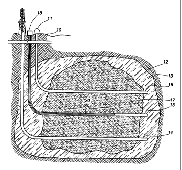
[0018] Figure 1 is a schematic diagram illustrating a heavy oil heating
process,
wherein wave guides are used to introduce the microwaves to the reservoir.
[0019] Figure 2 is a schematic diagram illustrating a heavy oil heating
process
wherein the microwaves are introduced into the reservoir using a microwave
generator located within the reservoir.
CA 02777859 2012-05-22
DETAILED DESCRIPTION
[0020] Turning
now to the detailed description of the preferred arrangement or
arrangements of the present invention, it should be understood that the
inventive
features and concepts may be manifested in other arrangements and that the
scope of
the invention is not limited to the embodiments described or illustrated. The
scope of
the invention is intended only to be limited by the scope of the claims that
follow.
[0021] The
selection of solvent to be used in the gravity drainage operation
includes those with a dipole moment so that the solvent can be heated by the
microwave frequencies. Types of solvents that can be used include water,
butane,
pentane, hexane, diesel and mixtures thereof In another embodiment the
selection of
the solvent does not include water to appease environmental and costs
concerns. In
another embodiments the solvent contains 90%, 80%, 70%, 60%, 50%, 40%, 30%,
20% even 10% water.
[0022] Turning
now to Figure 1, wellbores 14, 15 and 16 are illustrated.
Wellbore 14 extends from the surface 10 into a lower portion of subterranean
region
12. Wellbore 16 extends from the surface 10 into subterranean region 12 and
generally will be higher than wellbore 14. Wellbore 16 will be used to inject
solvent
and it is preferred that it is located higher than wellbore 14 so that when
the injected
solvent heats the heavy oil, the heavy oil will flow generally towards
wellbore 14,
which is used to extract the heavy oil from the reservoir. In one embodiment a
portion of the H20 is injected as steam and the steam contacts with at least a
portion
of the heavy oil in the region so as to heat the portion of the heavy oil and
reduce its
viscosity so that it flows generally towards the second wellbore. Wellbore 15
is used
to introduce microwaves to the reservoir and it is preferred that wellbore 15
be located
intermittent to wellbores 14 and 15; although, other arrangements are
possible.
[0023] In
operation, vapor generated in boiler 11 is provided into the reservoir
12 through upper wellbore leg 16. The vapor heats the heavy oil within zone 17
of
the oil-bearing portion 13 of reservoir 12 causing it to become less viscous
and,
hence, increase its mobility. The heated heavy oil flows downward by gravity
and is
produced through wellbore leg 14. While Figure 1 illustrates a single wellbore
for
injection and a single wellbore for extraction, other configurations are
within the
scope of the invention, for example, there can be two or more separate
wellbores to
provide steam injection and two or more separate wellbores for production.
Similarly,
6
CA 02777859 2012-05-22
=
=
multiple wellbores can be used for microwave introduction to the reservoir, as
further
discussed below.
[0024]
Generally, the wellbore for steam injection, wellbore 16, will be
substantially parallel to and situated above the wellbore for production,
wellbore 14,
which is located horizontally near the bottom of the formation. Pairs of vapor
injection wellbores and production wellbores will generally be close together
and
located at a suitable distance to create an effective steam chamber and yet
minimizing
the preheating time. Typically, the pairs of injection and production
wellbores will be
from about 3 meters to 7 meters apart and preferably there will be about 5
meters of
vertical separation between the injector and producer wellbores.
In other
embodiments it is possible for the injection and production wellbores be
anywhere
from 1, 3, 5, 7, 12, 15, 20 even 25 meters of horizontal separation apart.
Additionally,
in other embodiments it is possible for the injection and production wellbores
be
anywhere from 1, 3, 5, 7, 12, 15, 20 even 25 meters of vertical separation
apart. In
this type of SAGD operation, the zone 17 is preheated by steam circulation
until the
reservoir temperature between the injector and producer wellbore is at a
temperature
sufficient to drop the viscosity of the heavy oil so that it has sufficient
mobility to
flow to and be extracted through wellbore 14. Generally, the heavy oil will
need to be
heated sufficiently to reduce its viscosity to below 3000 cP; however, lower
viscosities are better for oil extraction and, thus, it is preferable that the
viscosity be
below 1500 cP and more preferably below 1000 cP. Preheating zone 17 involves
circulating vapor inside a liner using a tubing string to the toe of the
wellbore. Both
the injector and producer would be so equipped. Vapor circulation through
wellbores
14 and 16 will occur over a period of time, typically about 3 months. During
the
steam circulation, heat is conducted through the liner wall into the reservoir
near the
liner. At some point before the circulation period ends, the temperature
midway
between the injector and producer will reach a temperature wherein the bitumen
will
become movable typically around 3000 cP or less or from about 80 to 100 C.
Once
this occurs, the steam circulation rate for wellbore 14 will be gradually
reduced while
the steam rate for the injector wellbore 16 will be maintained or increased.
This
imposes a pressure gradient from high, for the area around wellbore 16, to
low, for the
area around wellbore 14. With the oil viscosity low enough to move and the
imposed
pressure differential between the injection and production wellbores, vapor
(usually
condensed to hot solvent) starts to flow from the injector into the producer.
As the
7
CA 02777859 2012-05-22
=
*
vapor rate is continued to be adjusted downward in wellbore 14 and upward in
wellbore 16, the system arrives at solvent assisted gravity drainage operation
with no
vapor injection through wellbore 14 and all the vapor injection through
wellbore 16.
Once hydraulic communication is established between the pair of injector and
producer wellbores, steam injection in the upper well and liquid production
from the
lower well can proceed. Due to gravity effects, the vapor tends to rise and
develop a
solvent chamber at the top section 19 of zone 17. The process is operated so
that the
liquid/vapor interface is maintained between the injector and producer
wellbores to
form a vapor trap which prevents live vapor from being produced through the
lower
wellbore.
[0025] During operation, vapor will come into contact with the
heavy oil in
zone 17 and, thus, heat the heavy oil and increase its mobility by lessening
its
viscosity. Heated heavy oil will tend to flow downward by gravity and collect
around
wellbore 14. Heated heavy oil is produced through wellbore 14 as it collects.
Vapor
contacting the heavy oil will lose heat and tend to condense into solvent. The
solvent
will also tend to flow downward toward wellbore 14. In past SAGD operations,
water
would also be produced through wellbore 14. Such produced water would need to
be
treated to reduce impurities before being reheated in the boiler for
subsequent
injection. As the process continues operation, zone 17 will expand with heavy
oil
production occurring from a larger portion of oil-bearing portion 13 of
subterranean
formation 12.
[0026] Turning again to Figure 1, the current invention
provides for
microwave generator 18 to generate microwaves which are directed underground
and
into zone 17 of the reservoir through a series of wave guides 20. The diameter
of the
wave guides will preferably be more than 3 inches in order to ensure good
transmission of the microwaves. Within the reservoir, the microwaves will be
at a
frequency substantially equivalent to the resonant frequency of the water
within the
reservoir so that the microwaves excite the water molecules causing them to
heat up.
Optimally, the microwaves will be introduced at or near the liquid vapor
interface so
that condensed vapor is reheated from its solvent state back into vapor
further
supplying the steam chamber. In some embodiments the microwave frequency will
be not greater than 3000 megahertz and/or at a resonant frequency of water.
Based on
the resonant frequency of water, the optimum frequency will be 2450 megahertz;
however, power requirements and other factors may dictate that another
frequency is
8
CA 02777859 2012-05-22
=
more economical. Additionally, salt and other impurities may enhance the
coupling
effect (production of heat by resonance of a polar or conductive molecule with
microwave energy); thus, the presence of salt is desirable.
[0027]
Turning now to Fig. 2, a further embodiment of the invention is
illustrated wherein, instead of using wave guides, power is supplied through
electrical
wire 22 to microwave generating probe 24. The electrical power can be supplied
to
wire 22 by any standard means such as generator 26.
[0028] In
still another embodiment of the invention, also illustrated in Fig. 2,
no vapor boiler is used. Instead solvent is introduced directly into wellbore
16
through pipe 28 and valve 30. Wellbore 16 then introduces solvent into the
reservoir
instead of vapor and the entire vapor production would be accomplished through
use
of the microwave generators. This embodiment of the invention has the added
advantage of avoiding costly water treatment that is necessary when using a
boiler to
generate steam because, as discussed above, salt and other impurities can aid
in heat
generation. In a preferred embodiment, the solvent introduced into the
reservoir
would have a salt content greater than the natural salt content of the
reservoir, which
is typically about 5,000 to 7,000 ppm. Accordingly, it is preferred that the
introduced
solvent has a salt content greater than 10,000 ppm. For enhanced heat
generation
30,000 to 50,000 ppm is more preferred.
[0029]
Microwave generators useful in the invention would be ones suitable
for generating microwaves in the desired frequency ranges recited above.
Microwave
generators and wave guide systems adaptable to the invention are sold by Cober
Muegge LLC, Richardson Electronics and CPI International Inc.
[0030]
Solvent to oil ratio is an important factor in SAGD operations and
typically the amount of solvent required will be 2 to 3 times the oil
production.
Higher solvent to oil production ratios require higher solvent and natural gas
costs.
The present invention reduces solvent and natural gas requirements and reduces
some
of the solvent handling involving recycling, cooling, and cleaning up the
water.
[0031] In
closing, it should be noted that the discussion of any reference is not an
admission that it is prior art to the present invention, especially any
reference that may
have a publication date after the priority date of this application. At the
same time,
each and every claim below is hereby incorporated into this detailed
description or
specification as additional embodiments of the present invention.
9
CA 02777859 2015-11-05
[0032] Although the
systems and processes described herein have been described
in detail, it should be understood that various changes, substitutions, and
alterations
can be made without departing from the scope of the invention as defined by
the
following claims. Those skilled in the art may be able to study the preferred
embodiments and identify other ways to practice the invention that are not
exactly as
described herein. The scope of the claims should not be limited by the
preferred
embodiments set forth in the description, but should be given the broadest
interpretation consistent with the description as a whole.