Note: Descriptions are shown in the official language in which they were submitted.
CA 02777977 2012-05-24
232400
FLADE DUCT TURBINE COOLING AND POWER AND THERMAL
MANAGEMENT
BACKGROUND OF THE INVENTION
TECHNICAL FIELD
The present invention relates generally to aircraft gas turbine engine and
aircraft cooling
and, more specifically, to such systems for cooling aircraft power and thermal
management systems and gas turbine engine turbines.
BACKGROUND INFORMATION
Military aircraft designs are being developed with engines that will operate
at much
higher overall pressure ratios than today's engines. Cooling air for hot
sections of the
engine's turbine, particularly, the high pressure turbine will be needed. It
is known to use
compressor air to cool the turbine such as disclosed in U.S. Pat. Nos.
4,187,675,
4,254,618, 7,823,389. Cooling air for aircraft avionics and other airframe
cooling
requirements may also be supplied by the compressor. The Lockheed F35 has
included
integrated power and cooling systems also referred to as power and thermal
management
systems which use compressor air.
U.S. Pat. No. 7,624,592 discloses a power and cooling management system
configured to
flexibly couple various adaptive modules to an integrated power and cooling
unit to suit
any aircraft platform is provided. The integrated power and cooling unit has a
compressor(s), power turbine(s), cooling turbine(s) and integral starter
generator(s)
mounted to the shaft of the power and cooling turbine. The integrated power
and cooling
unit may be pneumatically and/or pneumatically coupled to an adaptive module
that
comprises an additional compressor and an additional turbine or electrically
coupled to a
fuel cell which provides the main power after entering the full operation
mode. When the
-1-
CA 02777977 2012-05-24
232400
engine includes an integral starter generator mounted thereto, the integral
starter generator
of the integrated power and cooling unit is operative to receive electric
power from the
engine mounted generator. Alternatively, a motor/generator may be mounted to
the shaft
of the additional turbine of the adaptive module.
Other examples of integrated power and cooling systems discussed in U.S. Pat.
No.
7,624,592 include U.S. Pat. Nos. 4,684,081, 4,494,372, 4,684,081, 4,503,666,
5,442,905,
5,490,645, 6,415,595, and 6,845,630. The inventors of 7,624,592 found that
these
designs were complex and wanted to reduce the complexity of the engine
configuration
and its integrated power and cooling systems. Typically, these cooling systems
use fan
cooling air.
Thus, there is a need to supply cool compressor air for both turbine and
avionics and
other aircraft or airframe required cooling. There is also a need to make such
a cooling
system as simple and light weight with a minimal effect on fuel specific fuel
consumption
(SFC) as possible.
BRIEF DESCRIPTION OF THE INVENTION
An aircraft compound cooling system includes a power thermal management system
with
an air cycle system, a turbine cooling circuit for cooling pressurized bleed
air and using
the cooled pressurized bleed air for cooling turbine components in a high
pressure turbine
in an aircraft gas turbine engine, an air to air FLADE duct heat exchanger
disposed in a
FLADE duct of the engine, and valving apparatus operable for selectively
switching the
air to air FLADE duct heat exchanger between the turbine cooling circuit and
the air cycle
system.
An exemplary embodiment of the aircraft compound cooling system further
includes the
air cycle system in heat transfer cooling relationship with a vapor cycle
system condenser
in the vapor cycle system. An engine burn fuel to air heat exchanger may be in
heat
transfer cooling relationship with the vapor cycle system condenser.
-2-
CA 02777977 2012-05-24
232400
An air cycle system heat exchanger may be incorporated in the vapor cycle
system
condenser and be used for cooling a working fluid in a refrigeration loop of
the vapor
cycle system with cooling air from the air cycle system. The engine burn fuel
to air heat
exchanger is operable for cooling the working fluid in the refrigeration loop
of the vapor
cycle system with engine burn fuel.
The vapor cycle system may be operably connected to and for cooling an
environmental
control system for cooling liquid and/or air cooled aircraft components.
The air cycle system may include an air cycle machine having a power turbine
drivingly
connected to a machine compressor and a cooling turbine of the air cycle
machine. An
intercooler including the FLADE duct heat exchanger is operably disposed in
serial
airflow relationship between a machine compressor outlet of the machine
compressor and
a cooling turbine inlet of the cooling turbine. The air cycle system heat
exchanger is
operably disposed in serial airflow relationship between a cooling turbine
outlet of the
cooling turbine and a machine compressor inlet of machine compressor and the
power
turbine is connected to and in pressurized air receiving relationship with a
compressor
stage of an aircraft gas turbine engine high pressure compressor such as a
compressor
discharge stage.
The exemplary embodiment of the aircraft compound cooling system further
includes
inlet and outlet lines leading to and from the air to air FLADE duct heat
exchanger
respectively. The valving apparatus includes inlet and outlet valves connected
to the inlet
and outlet lines respectively. The compressor discharge stage is operably
connected by a
bleed line to a first inlet of the inlet valve and the compressor outlet of
the machine
compressor is operably connected by a compressor outflow line to a second
inlet of the
inlet valve. The inlet line to the air to air FLADE duct heat exchanger is
operably
connected to an outlet of the inlet valve and an outlet line from the air to
air FLADE duct
heat exchanger is operably connected to a valve inlet of the outlet valve. The
turbine
cooling circuit is operably connected to a first outlet of the outlet valve. A
bypass line
-3-
CA 02777977 2012-05-24
232400
may operably connect a first bypass outlet of the inlet valve to a second
bypass outlet of
the outlet valve.
A wire-wound induction magnet generator may be on a shaft connecting the power
turbine to the machine compressor and the cooling turbine.
The cooling turbine components in a high pressure turbine may include first
stage turbine
blades.
BRIEF DESCRIPTION OF THE DRAWINGS
FIG. I is a diagrammatical view illustration of a gas turbine engine powered
aircraft
having a compound cooling system using a heat exchanger mounted in a FLADE
duct
operable to alternatively cool air for turbine cooling or aircraft component
cooling.
FIG. 2 is diagrammatical view of duct heat exchanger elements distributed
around and in
a FLADE duct of the engine illustrated in FIG. 1.
FIG. 3 is a more detailed view illustration of an exemplary turbine cooling
system
illustrated in FIG. 1.
DETAILED DESCRIPTION OF THE INVENTION
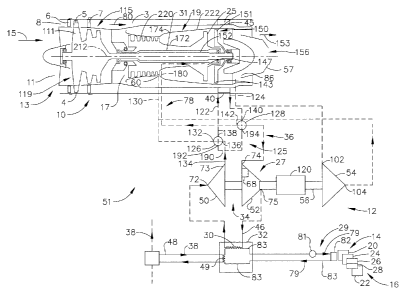
Illustrated diagrammatically in FIG. 1 is an exemplary aircraft FLADE gas
turbine engine
including an air to air FLADE duct heat exchanger 40 disposed in a FLADE duct
3 of
the engine 10. The heat exchanger 40 may include heat exchanger sections 45
distributed
around the FLADE duct 3 as illustrated in FIG. 2. A compound cooling system 51
uses
the air to air FLADE duct heat exchanger 40 to alternatively cool compressor
air for
turbine cooling or cooling air for aircraft component cooling. The compound
cooling
system 51 is operable to cool hot pressurized bleed air 58 for cooling turbine
components
in a high pressure turbine 23 of the engine 10 or alternatively switched to
cool cooling air
46 for use in an air cycle system 27 used to cool a power thermal management
system
(PTMS) 12. The pressurized bleed air 58 is bled from a compressor discharge
stage 60 of
-4-
CA 02777977 2012-05-24
232400
a high pressure compressor 64 of the aircraft gas turbine engines 10. The
FLADE duct 3
is a good location for the duct heat exchanger 40 because there is typically
fewer FLADE
stages than fan stages and so the FLADE duct airflow is cooler.
Referring to FIG. 1, a turbine cooling circuit 78 directs the pressurized
bleed air 58 from
the compressor discharge stage 60, through the FLADE duct heat exchanger 40,
and into
the high pressure turbine 23 of the engine 10. Pressurized bleed air 58 from
the
compressor discharge stage 60 is often referred to as CDP air or bleed. CDP is
a well
known acronym for compressor discharge pressure. The power thermal management
system 12 includes an air cycle system ACS 27. The ACS 27 includes an air
cycle
machine (ACM) 34 and an intercooler 36 including the air to air duct heat
exchanger 40.
The ACS 27 is used to provide cooling for liquid and/or air cooled aircraft
components 16
and equipment as well as thermal control and pressurization for the cockpit
through what
is often referred to as an environmental control system (ECS) 14. Exemplary
cooled
aircraft components 16 include directed energy weapons (DEW) 20, avionics 22,
alternating current (A/C) electronics 24, onboard inert gas generation systems
(OBIGGS)
26, and onboard oxygen gas generation systems (OBOGS) 28.
The turbine cooling circuit 78 cools pressurized bleed air 58 and uses the
cooled
pressurized bleed air 58 for cooling turbine components in the high pressure
turbine 23.
The power thermal management system 12 uses cooling air 46 in the air cycle
system 27
used to cool the environmental control system 14. Valving apparatus 125
selectively
switches the air to air FLADE duct heat exchanger 40 between the turbine
cooling circuit
78 and the air cycle system 27.
A FLADE engine (FLADE being an acronym for "fan on blade") is one particular
type of
variable cycle engines characterized by an outer fan driven by a radially
inner fan and
discharging its FLADE air into an outer fan duct which is generally co-annular
with and
circumscribes an inner fan duct circumscribing the inner fan. One such engine,
disclosed
in U.S. Pat. No. 4,043,121, entitled "Two Spool Variable Cycle Engine", by
Thomas et
al., provides a FLADE fan and outer fan duct within which variable guide vanes
control
-5-
CA 02777977 2012-05-24
232400
the cycle variability by controlling the amount of air passing through the
FLADE outer
fan duct.
FLADE engines are capable of maintaining an essentially constant inlet airflow
over a
relatively wide range of thrust at a given set of subsonic flight ambient
conditions such as
altitude and flight Mach No. in order to avoid spillage drag and to do so over
a range of
flight conditions. This capability is particularly needed for subsonic part
power engine
operating conditions. Examples of these are disclosed in U.S. Pat. No.
5,404,713, entitled
"Spillage Drag and Infrared Reducing FLADE Engine", U.S. Pat. No. 5,402,963,
entitled
"Acoustically Shielded Exhaust System for High Thrust Jet Engines", U.S. Pat.
No.
5,261,227, entitled "Variable Specific Thrust Turbofan Engine", and European
Patent No.
EPO,567,277, entitled "Bypass Injector Valve For Variable Cycle Aircraft
Engines".
United States Patent 7,395,657, entitled "Flade gas turbine engine with fixed
geometry
inlet" is incorporated herein by reference.
The engine 10 includes a fan section 115 having a three stage fan 119 and a
FLADE fan 4
having at least one row of FLADE fan blades 5 extending radially across the
FLADE duct
3. The FLADE fan 4 and FLADE fan blades 5 are disposed radially outwardly of,
connected to, and circumscribed about the fan 119. An engine inlet 13 includes
a fan
inlet 11 to the fan section 115 and an annular FLADE inlet 8 to the FLADE duct
3.
FLADE airflow 80 is exhausted by the FLADE fan blades 5. The row of FLADE fan
blades 5 is disposed radially outwardly of, operably connected to, and driven
by a first fan
stage 111 of the three stage fan 119. The row of FLADE fan blades 5 is
disposed
between an axially forward row of variable first FLADE vanes 6 and,
optionally, an
axially aft row of variable second FLADE vanes 7.
Downstream and axially aft of the fan 119 is a core engine 19 having an
annular core
engine inlet 17. A fan bypass duct 41 located downstream and axially aft of
the fan 119
circumscribes the core engine 19. The FLADE duct 3 circumscribes the fan 119
and the
fan bypass duct 41. The fan inlet 11 is sized to receive essentially full
engine airflow 15
of the engine at full power conditions with the FLADE inlet 8 essentially
closed off by
-6-
CA 02777977 2012-05-24
232400
closing the variable first FLADE vanes 6 and the variable second FLADE vanes
7. The
engine is further designed and operated to fully open the inlet of the FLADE
duct 3 at
predetermined part power flight conditions and essentially close it at full
power
conditions such as take-off.
The core engine 19 includes, in downstream serial axial flow relationship, a
high pressure
compressor 220, a combustor 222, and the high pressure turbine 23 having a row
of high
pressure turbine blades 25. A high pressure shaft 31, disposed coaxially about
the
centerline 212 of the engine 10, fixedly interconnects the high pressure
compressor 220
and the high pressure turbine blades 25. The core engine 19 is effective for
generating
combustion gases. Pressurized air from the high pressure compressor 220 is
mixed with
fuel in the combustor 222 and ignited, thereby, generating combustion gases.
Some work
is extracted from these gases by the high pressure turbine blades 25 which
drives the high
pressure compressor 220. The high pressure shaft 31 rotates the high pressure
compressor 220.
The combustion gases are discharged from the core engine 19 into a low
pressure turbine
section 150 having a low pressure turbine 151. The low pressure turbine 151 is
drivingly
connected to the fan 119 by a low pressure shaft 152. The FLADE fan blades 5
are
primarily used to flexibly match inlet airflow requirements. Engine exhaust
now 153
from the low pressure turbine section 150, the FLADE duct 3, and the fan
bypass duct 41
is exhausted through an exhaust nozzle 156.
The air to air FLADE duct heat exchanger 40 is operable to cool the hot
pressurized bleed
air 58 from the compressor discharge stage 60 and exhaust it as pressurized
cooling air
179. Alternatively, the air to air FLADE duct heat exchanger 40 is operable to
cool
cooling air 46 in the intercooler 36 of the ACS 27 for the air cycle machine
(ACM) 34.
Referring to FIGS. 1 and 3, the turbine cooling circuit 78 bleeds the hot
pressurized bleed
air 58 from the compressor discharge stage 60, flows the hot pressurized bleed
air 58 to
the air to air FLADE duct heat exchanger 40 for cooling to form the
pressurized cooling
-7-
CA 02777977 2012-05-24
232400
air 179, and flows the cool pressurized air 179 to a plurality of
circumferentially spaced
apart transfer tubes 180 extending radially through inner and outer combustor
casings
172, 174 of the combustor 222. The plurality of circumferentially spaced apart
transfer
tubes 180 are part of the turbine cooling circuit 78. The pressurized cooling
air 179 is
then flowed to an annular flow inducer 84 which then directs the pressurized
cooling air
179 to a row of first stage turbine blades 143 extending radially outwardly
from their
supporting rotor disk 147 in the high pressure turbine. The first stage
turbine blades 143
are examples of turbine components in a high pressure turbine 23 that may be
cooled by
the turbine cooling circuit 78.
The flow inducer 84 is a stationary component typically including a row of
vanes which
tangentially accelerates, meters, and/or further pressurizes the pressurized
cooling air 179
and injects the pressurized cooling air 179 into a rotating first stage rotor
disk 147. This
is a conventional component for efficiently channeling and metering the
pressurized
cooling air 179 to the axial dovetail slots of the disk 147 for flow into the
inlets found in
the dovetails of the turbine blades 143. The pressurized cooling air 179 flows
radially
outwardly through the turbine blades 143 and cooling channels 165 therein and
is
discharged through the several rows of discharge holes 168 in the pressure and
suction
sides of the blade airfoil.
Referring to FIG. 1, the environmental control system (ECS) 14 is cooled by
the air cycle
system ACS 27 and a vapor cycle system (VCS) 29. The ACS 27 includes an air
cycle
machine (ACM) 34 and the intercooler 36 including the an air to air duct heat
exchanger
40. The intercooler 36 is used to cool cooling air 46 cooled by the ACM 34. An
air cycle
system heat exchanger 30 in the air cycle system ACS 27 is used to help cool
the vapor
cycle system (VCS) 29.
The duct heat exchanger 40 is used to cool cooling air 46 flowing between a
machine
compressor 50 and a cooling turbine 52 of the ACM 34. The cooling air 46 is
directed
from the machine compressor 50, through the intercooler 36, into the cooling
turbine 52.
The cooling air 46 exiting the cooling turbine 52 is then used to cool a
working fluid 79
-8-
CA 02777977 2012-05-24
232400
in a vapor cycle system (VCS) condenser 32 of the VCS 29. The working fluid 79
may
be a well known refrigerant such as R-134a.
The VCS 29 further includes a VCS compressor 81 and a VCS evaporator 82. The
working fluid 79 is recirculated in a refrigeration loop 83 from the VCS
condenser 32 to
the VCS compressor 81 to VCS evaporator 82 which cools air used for cooling
the
aircraft components 16 and then back to the VCS condenser 32. The air cycle
system
heat exchanger 30 in the ACS 27 may be used in the vapor cycle system
condenser 32 for
cooling the working fluid 79 in the refrigeration loop 83 with the cooling air
46 exiting
the cooling turbine 52.
An engine burn fuel to air heat exchanger 49 is also used to cool the working
fluid 79 in
the vapor cycle system condenser 32 in the VCS 29. The engine burn fuel to air
heat
exchanger 49 is in thermal communication with engine burn fuel 38 used to fuel
the
aircraft gas turbine engines 10. The engine fuel to air heat exchanger 49 is
in a
polyalphaolefin (PAO) loop 48 which is used cool the working fluid 79
recirculating in
the refrigeration loop 83. The engine burn fuel to air heat exchanger 49 is
illustrated as
being in the VCS condenser 32 but could located elsewhere for cooling the
working fluid
79.
The ACM 34 includes an ACM power turbine 54 for driving the machine compressor
50
and the cooling turbine 52 through a shaft 56. The ACM power turbine 54 is
powered by
pressurized bleed air 58 from the compressor discharge stage 60 of the high
pressure
compressor 64 of the aircraft gas turbine engines 10. The pressurized bleed
air 58 from
the compressor discharge stage 60 flows into a power turbine inlet 102 of the
power
turbine 54. The pressurized bleed air 58 exhausted through a power turbine
outlet 104
from the ACM power turbine 54 and is dumped into engine exhaust 86 upstream of
a
throat 57 in the exhaust nozzle 156.
The exemplary ACM 34 illustrated herein includes an centrifugal machine
compressor 50
including a machine compressor inlet 72 and a compressor outlet 73, a radial
inflow
-9-
CA 02777977 2012-05-24
232400
cooling turbine 52 including a cooling turbine inlet 74 and a cooling turbine
outlet 75,
and a radial inflow ACM power turbine 54. The air cycle system heat exchanger
30 in the
ACS 27 is operably disposed in airflow relationship between the cooling
turbine outlet 75
and the machine compressor inlet 72. The exemplary cooling turbine 52
illustrated herein
has a fixed cooling turbine nozzle 68, but it may be a variable nozzle to
maintain the
machine compressor on its operating line for stall margin.
The ACM 34 may also include a generator 120 on the same shaft 56 drives as the
machine compressor 50 and the cooling turbine 52. The generator 120 provides
electrical
power for starting the engine 10 when the ACS 27 operates as an APU (auxiliary
power
unit). Generator starting magnetic induction current is supplied from a
battery (not
shown). On a 2-engine aircraft, this APU function might not be needed so long
as the
engine can be started with a ground cart. The generator 120 may alternatively
be an
electrical starter/generator.
The compound cooling system 51 includes inlet and outlet lines 122, 124
leading to and
from the air to air FLADE duct heat exchanger 40 respectively. Three way inlet
and
outlet valves 126, 128 to inlet and outlet lines 122, 124 provide an exemplary
valving
apparatus 125 for selectively switching the air to air FLADE duct heat
exchanger 40
between the turbine cooling circuit 78 and the air cycle system 27. The
compressor
discharge stage 60 is connected by a bleed line 130 to a first inlet 132 of
the inlet valve
126. The compressor outlet 73 of the machine compressor 50 is connected by a
compressor outflow line 134 to a second inlet 136 of the inlet valve 126. The
inlet line
122 to the air to air FLADE duct heat exchanger 40 is connected to an outlet
138 of the
inlet valve 126.
An outlet line 124 from the air to air FLADE duct heat exchanger 40 is
connected to a
valve inlet 140 of the outlet valve 128. The plurality of circumferentially
spaced apart
transfer tubes 180 extending radially through the inner and outer combustor
casings 172,
174 of the high pressure compressor 220 illustrated in FIG. 3 are connected to
a first
outlet 142 of the outlet valve 128.
-10-
CA 02777977 2012-05-24
232400
A bypass line 190 connects a first bypass outlet 192 of the inlet valve 126 to
a second
bypass outlet 194 of the outlet valve 128. The bypass line 190 enables the
turbine cooling
circuit 78 to direct the pressurized bleed air 58 from the compressor
discharge stage 60
and into the high pressure turbine of the engine 10 while bypassing the FLADE
duct heat
exchanger 40 when the compound cooling system 51 is switched to cool cooling
air 46
for use in a power thermal management system (PTMS) 12. The bypass line 190
also
enables the power thermal management system (PTMS) 12 to direct the cooling
air 46
from the compressor outlet 73 of the compressor 50 and into to a radial inflow
cooling
turbine 52 including the cooling turbine inlet 74 of the cooling turbine 52
while bypassing
the FLADE duct heat exchanger 40 when the compound cooling system 51 is
switched to
cool the hot pressurized bleed air 58 for cooling turbine components in the
high pressure
turbine of the engine 10.
Cooling available to the ACM 34 from the air to air FLADE duct heat exchanger
40 is
cutoff during high power flight when there is a large amount of the engine
burn fuel 38
flowing through the engine fuel to air heat exchanger 49, thus, providing a
great deal of
cooling for the vapor cycle system 29. During high power flight conditions,
the hot
pressurized bleed air 58 from the compressor discharge stage 60 is cooled in
the FLADE
duct heat exchanger 40 and flowed as pressurized cooling air 179 to the
turbine cooling
circuit 78. This is particularly useful because the turbine components cooled
by the
pressurized cooling air 179 are subject to very high temperature conditions
during high
power flight conditions.
During lower power flight conditions, the turbine is not subject to as high
temperature
conditions and the air to air FLADE duct heat exchanger 40 is switched into
the air cycle
system 27. During lower power flight conditions, there is less engine burn
fuel 38
flowing through the engine fuel to air heat exchanger 49, thus, the air to air
FLADE duct
heat exchanger 40 provides a great deal of cooling for the vapor cycle system
29.
While there have been described herein what are considered to be preferred and
exemplary embodiments of the present invention, other modifications of the
invention
-11-
CA 02777977 2012-05-24
232400
shall be apparent to those skilled in the art from the teachings herein and,
it is therefore,
desired to be secured in the appended claims all such modifications as fall
within the true
spirit and scope of the invention.
-12-