Note: Descriptions are shown in the official language in which they were submitted.
CA 02778134 2012-04-18
WO 2011/057663
PCT/EP2009/064986
- 1 -
PERISTALTIC PUMP AND HOSE CARTRIDGE THEREFOR
Technical Field
The invention relates to a peristaltic pump and more
particularly to a hose cartridge therefor. It relates to
methods and apparatuses according to the opening clauses of
the claims.
Background of the Invention
Peristaltic pumps are well known and widely used in
applications where a fluid to be pumped has to remain
particularly clean, e.g., in water analytics. A hose of an
elastic material and containing the fluid to be pumped is
mounted in a hose cartridge having an occlusion surface,
and the hose is located between said occlusion surface and
rollers of a roller wheel of the peristaltic pump, such
that when the roller wheel rotates, the fluid is
transported within the hose. Generally, not only liquid or
gaseous materials can be pumped this way, but also solid
CA 02778134 2015-12-09
2
material such as granular materials. The pumping of liquids is of particular
interest
for the present invention.
From US 2004/0057856 Al, a hose cartridge is known, which has a cantilever arm
at which the occlusion surface is located. A screw provides a stop for the
cantilever
movement of the cantilever arm, thus allowing to adjust the pressure exterted
on the
hose when the cartridge is mounted on a corresponding peristaltic pump.
In US 5 846 061, a multi channel peristaltic pump is presented.
Summary of the Invention
According to one aspect of the present invention, there is provided a hose
cartridge
for removably mounting a hose on a peristaltic pump comprising a roller wheel
for
pumping a fluid through said hose and a holding rod and a fixing bar, the hose
cartridge comprising:
parallel to a rotation axis of said roller wheel, said hose cartridge
substantially describing a closed loop encircling an opening through which
said roller
wheel extends when the hose cartridge is mounted on the peristaltic pump, the
hose
cartridge being rotatably clamped on the holding rod of the peristaltic pump,
wherein said hose cartridge is rotatable around an axis defined by said
holding rod
to move within said opening between an initial cartridge position and a
working
position in which said hose is compressed between said roller wheel and said
hose
cartridge, wherein said holding rod and said fixing bar extend through said
opening.
According to another aspect of the present invention, there is also provided a
method for mounting a hose cartridge comprising a hose onto a peristaltic pump
CA 02778134 2015-12-09
2a
comprising a roller wheel for pumping a fluid through said hose and a holding
rod
and a fixing bar, said holding rod and said fixing bar both extending
substantially
parallel to a rotation axis of said roller wheel, said method comprising the
steps of:
b) introducing said holding rod into a holding portion of said hose cartridge;
c) carrying out a rotational movement of said hose cartridge about an axis
defined by said holding rod until a working position of the hose cartridge is
reached,
wherein during step c), by means of said rotational movement, said fixing bar
is
slided over a sliding surface of a lever portion of the hose cartridge, and,
by further
rotating said hose cartridge about said axis defined by said holding rod, a
fixing
surface of said lever portion is pressed, by means of a spring member of said
lever
portion, against said fixing bar, thus holding said hose cartridge in said
working
position.
According to another aspect of the present invention, there is also provided a
method for mounting a hose cartridge comprising a hose onto a peristaltic pump
comprising a roller wheel for pumping a fluid through said hose and a holding
rod
and a fixing bar, said holding rod and said fixing bar both extending
substantially
parallel to a rotation axis of said roller wheel, said method comprising the
steps of:
b) introducing said holding rod into a holding portion of said hose cartridge;
c) carrying out a rotational movement of said hose cartridge about an axis
defined by said holding rod until a working position of the hose cartridge is
reached,
said hose cartridge comprising a receiving opening, said method comprising,
before step b), the step of
a) moving said hose cartridge with said receiving opening over said rotation
axis, said holding rod and said fixing bar, such that the latter extend
through said
receiving opening.
CA 02778134 2015-12-09
2b
Other aspects, objects, embodiments, variants and/or advantages of the present
invention, all being preferred and/or optional, are briefly summarized
hereinbelow.
For example, one object of the invention is to create a new type of hose
cartridge
and a corresponding peristaltic pump. In addition, the respective method for
mounting a hose cartridge onto a peristaltic pump shall be provided.
Another object of the invention is to provide a way to achieve a high
precision and
reproducibility in peristaltic pumping.
Another object of the invention is to provide a possibility to allow a simple
mounting
of a hose cartridge onto a peristaltic pump.
Another object of the invention is to provide a possibility to enable a high
degree of
reproducibility in mounting a hose cartridge onto a peristaltic pump.
CA 02778134 2012-04-18
WO 2011/057663
PCT/EP2009/064986
- 3 -
Another object of the invention is to provide a peristaltic
pump which can be provided with a relatively weak bearing
for the rotation axis of the roller wheel while still being
sufficiently sturdily designed.
Further objects emerge from the description and embodiments
below.
At least one of these objects is at least partially
achieved by apparatuses and methods according to the patent
claims.
The hose cartridge is a hose cartridge for removably
mounting a hose on a peristaltic pump comprising a roller
wheel for pumping a fluid through said hose. Said hose
cartridge substantially describes a closed loop encircling
an opening through which said roller wheel extends when the
hose cartridge is mounted on a peristaltic pump.
This provides a high degree of rigidness and mechanic
stability while allowing a relatively small overall design
using little material only.
Said hose typically is a flexible tube.
Said hose cartridge can also be considered a hose cartridge
for mounting a hose on and unmounting a hose from a
peristaltic pump.
Said roller wheel sometimes is also referred to as pump
head.
In one embodiment, the hose cartridge is of generally ring-
like shape, wherein "ring" does not imply a circular shape.
CA 02778134 2012-04-18
WO 2011/057663
PCT/EP2009/064986
- 4 -
In one embodiment which is of particular importance and
which may be combined with the before-addressed embodiment,
said peristaltic pump is a rotary peristaltic pump and/or a
tube pump.
In particular, during operation, said roller wheel rotates
around a substantially fixed rotation axis and the active
section of the hose describes an open loop, more particular
a segment of a circle of less than 3600, typically less
than 2700, more typically at most 180 . Under "active
section", we understand that section of the hose which
interacts with the roller wheel (i.e. which is compressed
by the roller wheel) when the hose cartridge is mounted on
a peristaltic pump and the peristaltic pump is in
operation.
In one embodiment which may be combined with one or more of
the before-addressed embodiments, said opening encircled by
said closed loop is referred to as an opening for receiving
the roller wheel, or shortly as "receiving opening". Said
receiving opening can also be considered to be an open
space surrounded by said closed loop into which the roller
wheel is to be inserted
In one embodiment which may be combined with one or more of
the before-addressed embodiments, said closed loop
surrounds an open space (receiving opening) into which the
roller wheel is located during pumping operation.
In one embodiment which may be combined with one or more of
the before-addressed embodiments, the hose cartridge
substantially describes a closed loop in a plane, wherein,
when the hose cartridge is mounted on a peristaltic pump,
CA 02778134 2012-04-18
WO 2011/057663
PCT/EP2009/064986
- 5 -
said plane is substantially perpendicular to a rotation
axis of said roller wheel, and said hose is arranged
substantially within said plane.
In one embodiment which may be combined with one or more of
the before-addressed embodiments, at least three rollers
are comprised in the roller wheel. Typically 4 or more or 5
or more are provided.
In one embodiment which may be combined with one or more of
the before-addressed embodiments, the rollers of the roller
wheel substantially are rotatable cylindrical members.
In one embodiment which may be combined with one or more of
the before-addressed embodiments, the shape of the hose
cartridge defines a cartridge plane, wherein said closed
loop is arranged within said cartridge plane. When the hose
cartridge is mounted on a peristaltic pump, a rotation axis
of the roller wheel will be arranged substantially
perpendicularly to said cartridge plane. With a hose .
inserted in the hose cartridge, the hose is generally
arranged within said cartridge plane.
In one embodiment which refers to the before-addressed
embodiment, the occlusion surface is aligned substantially
perpendicularly to said cartridge plane.
In one embodiment which may be combined with one or more of
the before-addressed embodiments, the direction of a lever
movement of a lever member of the hose cartridge lies
substantially within said cartridge plane (the lever member
is described below in more detail).
CA 02778134 2012-04-18
WO 2011/057663
PCT/EP2009/064986
- 6 -
In one embodiment which may be combined with one or more of
the before-addressed embodiments, the hose cartridge is a
hose cartridge for exactly one hose.
In one embodiment which may be combined with one or more of
the before-addressed embodiments, the hose cartridge is at
least substantially integrally formed or at least
substantially consists of an integrally formed main part
and an additional spring member or one or more parts of a
spring member attached to said main part.
This allows for a simple manufacturing and for a sturdy
design.
In one embodiment which may be combined with one or more of
the before-addressed embodiments, said hose cartridge is
made substantially of a polymer. Different materials or
combinations of materials are possible, including a hose
cartridge fully or partially of metal. The hose cartridge
can be completely rigid except for at least a portion of a
lever portion, where a degree of flexibility shall be
provided; lever portions are discussed further below.
In one embodiment which may be combined with one or more of
the before-addressed embodiments, the hose cartridge
comprises a first frame section forming an occlusion
surface having an at least substantially circular curvature
and a second frame section neighboring said first frame
section and forming a surface neighboring said occlusion
surface and having a curvature less strong than said
substantially circular curvature. This helps or enables to
mount the hose cartridge on a peristaltic pump by means of
a rotational movement.
CA 02778134 2012-04-18
WO 2011/057663
PCT/EP2009/064986
- 7 -
In one embodiment referring to the before-addressed
embodiment, said at least substantially circular curvature
is arranged within a plane substantially perpendicular to a
rotation axis of the roller wheel.
As to the occlusion surface: When the peristaltic pump is
in operation, the hose is compressed between said occlusion
surface and rollers of the roller wheel, or described
differently, with the hose inserted in the hose cartridge,
the active section of the hose is neighboring and in touch
with said occlusion surface.
Said radius of said circular curvature is substantially
determined by the outer diameter of the roller wheels and
the wall thickness of the hose.
In one embodiment which may be combined with one or more of
the before-addressed embodiments addressing the occlusion
surface, the occlusion surface is substantially strip-like,
more particularly, like a strip having said substantially
circular curvature in the direction of its extension and
being substantially flat (i.e. level) in the direction
perpendicular to its extension.
In one embodiment which may be combined with one or more of
the before-addressed embodiments, the hose cartridge
comprises said hose.
In one embodiment which may be combined with one or more of
the before-addressed embodiments, the hose cartridge
comprises a holding portion for rotatably fixing the hose
cartridge on a holding rod of a peristaltic pump.
CA 02778134 2012-04-18
WO 2011/057663
PCT/EP2009/064986
- 8 -
This allows to mount the hose cartridge by a rotating
movement.
In one embodiment referring to the before-addressed
embodiment, said holding portion fully or partially
encircles a shape substantially describing a cylinder
jacket.
In particular, it partially encircles said shape by an
angle of more than 1800 and less than 315 . This allows to
mount the hose cartridge on said holding rod by clamping.
/0 In one embodiment which may be combined with one or more of
the before-addressed embodiments, the hose cartridge
comprises a spring member and a lever portion. Therein,
said lever portion comprises
- a fixed end at which the lever portion is fixed to
substantially the rest of the hose cartridge; and
- a spring-loaded end, spring-loaded by said spring
member; and,
- at said spring-loaded end, a fixing surface; and,
- between said fixed end and said fixing surface and
neighboring said fixing surface, a sliding surface;
wherein said fixing surface and said sliding surface form
an angle of substantially larger than 180 .
This allows to reach a well-defined fixed position of the
hose cartridge when mounting the hose cartridge on a
peristaltic pump.
It is possible to dispense with a separate spring member
and design said lever portion in such a way that a
CA 02778134 2012-04-18
WO 2011/057663
PCT/EP2009/064986
- 9 -
sufficiently large force can be exterted on the fixing bar
by the lever portion alone, without an additional, separate
spring member.
In particular, said angle amounts to more than 2100, and
more particularly to more than 225 .
In one embodiment which may be combined with one or more of
the before-addressed embodiments addressing said fixing
surface, said fixing surface or at least its major portion
is substantially flat.
/0 In one embodiment which may be combined with one or more of
the before-addressed embodiments addressing said fixing
surface, a force exerted by spring member is directed
generally perpendicularly to said fixing surface, in
particular within 30 , more particularly within 20
perpendicularly thereto. Furthermore, said force is
preferably directed along a direction lying generally
within a plane perpendicular to the rotation axis of the
roller wheel.
In one embodiment which may be combined with one or more of
the before-addressed embodiments addressing said spring
member and said lever portion, these are provided for
securing the hose cartridge to a peristaltic pump, more
particularly for securing the hose cartridge to a fixing
bar of a peristaltic pump, and for allowing the fixing bar
to slide along the sliding surface when bringing the hose
cartridge into a fixed position or working position, in
particular by rotating the hose cartridge, in particular
about the above-mentioned holding rod. In the fixed
CA 02778134 2012-04-18
WO 2011/057663
PCT/EP2009/064986
- 10 -
position, the hose cartridge can be fixed in a clamping
fashion.
The force by which the hose is compressed by the rollers of
the roller wheels is determined by the force exerted by the
spring member in conjunction with the lever portion, and
can therefore be very well defined.
The fixing surface furthermore avoids a tiliting of the
hose cartridge. The fixing surface extends in a plane
perpendicular to the cartridge plane, and its extension
into a direction along the rotation axis of the roller
wheel ensures, by interaction with said fixing bar, that
the cartridge plane remains at least substantially
perpendicularly to the rotation axis of the roller wheel.
This applies in particular in conjunction with the above-
mentioned holding portion.
The spring member together with the lever portion allows to
ensure a defined tension on the hose, in particular in
conjunction with the above-mentioned holding portion and
holding rod. This relieves the roller wheel (more
particularly its rotation axis) from mechanical tension,
more particularly from forces likely to cause an axis tilt,
thus allowing to design the peristaltic pump with
relatively simple bearings for the rotation axis.
In one embodiment which may be combined with one or more of
the before-addressed embodiments, the hose cartridge
comprises an axial-positioning member, e.g., a protrusion
or a protuding part such as a nose, e.g., near and/or
opposite the fixing surface - for preventing a tilting of
the hose cartridge with respect to the rotation axis of the
CA 02778134 2012-04-18
WO 2011/057663
PCT/EP2009/064986
- 11 -
peristaltic pump, when the cartridge is mounted on a
peristaltic pump, and in particular during pumping
operation of the peristaltic pump. Through such a tilting
of the hose cartridge, the hose might become axially
displaced such that it would discontinue being compressed
between the rollers of the roller wheel and the occlusion
surface, and thus, the pumping would be disturbed. Such an
axial-positioning member can, e.g., interact with a fixing
bar of the peristaltic pump.
/0 In one embodiment which may be combined with one or more of
the before-addressed embodiments, the hose cartridge
comprises a stop member for preventing a too far rotation
of the hose cartridge when mounting the hose cartridge, in
particular wherein the stop member interacts with a fixing
bar of the peristaltic pump.
It is possible to embody the axial-positioning member as a
protrusion protuding from the stop member.
In one embodiment which may be combined with one or more of
the before-addressed embodiments, the hose cartridge is
substantially rigid (and remains substantially undeformed
during mounting / unmounting to/from a peristaltic pump and
during operation of the peristaltic pump), except for said
spring member and said lever portion and possibly also
except for said holding portion or a portion thereof.
The peristaltic pump comprises a roller wheel rotatable
about a substantially fixed rotation axis, and at least one
hose cartridge according to the invention and comprising a
hose.
CA 02778134 2012-04-18
WO 2011/057663
PCT/EP2009/064986
- 12 -
In one embodiment referring to the before-addressed
embodiment, the peristaltic pump comprises a holding rod
and a fixing bar, both aligned substantially parallel to
said rotation axis, and a fixing plate mechanically
interconnecting an end region of said holding rod, an end
region of said fixing bar and an end region of said
rotation axis.
This is for stabilizing the rotation axis and takes
mechanical stress from the rotation axis.
When mounted on a peristaltic pump, the hose cartridge will
usually be arranged (with respect to its axial position)
between said fixing plate and a housing of the peristaltic
pump, said housing at least containing a drive for rotating
said rotation axis.
E.g., said fixing plate is substantially a flat piece of
metal.
Viewed from a particular point of view, the invention
comprises a peristaltic pump which comprises a roller wheel
rotatable about a substantially fixed rotation axis and a
holding rod and a fixing bar, both aligned substantially
parallel to said rotation axis, and a fixing plate
mechanically interconnecting an end region of said holding
rod, an end region of said fixing bar and an end region of
said rotation axis.
The invention generally comprises peristaltic pumps with
features of corresponding hose cartridges according to the
invention, and vice versa. The advantages of the
peristaltic pumps basically correspond to the advantages of
corresponding hose cartridges and vice versa.
CA 02778134 2012-04-18
WO 2011/057663
PCT/EP2009/064986
- 13 -
The method is a method for mounting a hose cartridge
comprising a hose onto a peristaltic pump comprising a
roller wheel for pumping a fluid through said hose and a
holding rod and a fixing bar. Therein, said holding rod and
said fixing bar, both, extend substantially parallel to a
rotation axis of said roller wheel. The method comprises
the steps of
b) introducing said holding rod into a holding portion of
said hose cartridge;
/0 c) carrying out a rotational movement of said hose
cartridge about an axis defined by said holding rod
until a working position of the hose cartridge is
reached.
In one embodiment of the method, step b) comprises clamping
said holding rod into said holding portion, in particular
by pressing; more particularly by pressing the holding rod
through an opening of said holding portion; in particular,
said pressing is substantially accomplished by applying to
the hose cartridge a force substantially perpendicular to
said holding rod.
In one embodiment which may be combined with the before-
addressed embodiment of the method, during step c), by
means of said rotational movement, said fixing bar is
slided over a sliding surface of a lever portion of the
hose cartridge, and, by further rotating said hose
cartridge about said axis defined by said holding rod, a
fixing surface of said lever portion is pressed, by means
of a spring member of said lever portion, against said
CA 02778134 2012-04-18
WO 2011/057663
PCT/EP2009/064986
- 14 -
fixing bar, thus holding said hose cartridge in said
working position.
In one embodiment which may be combined with one or more of
the before-addressed method embodiments, said hose
cartridge comprises a receiving opening, and said method
comprises, before step b), the step of
a) moving said hose cartridge with said receiving opening
over said rotation axis, said holding rod and said
fixing bar, such that the latter extend through said
receiving opening.
The invention generally comprises methods for mounting a
hose cartridge onto a peristaltic pump with features of
corresponding hose cartridges and/or peristaltic pumps
according to the invention, and vice versa.
The advantages of the methods basically correspond to the
advantages of corresponding apparatuses and vice versa.
Further embodiments and advantages emerge from the
dependent claims and the figures.
Brief Description of the Drawings
Below, the invention is described in more detail by means
of examples and the included drawings. The figures show:
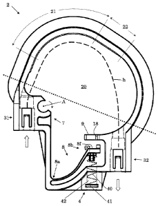
Fig. 1 a front view of a hose cartridge, no hose
mounted;
CA 02778134 2012-04-18
WO 2011/057663
PCT/EP2009/064986
- 15 -
Fig. 2 a perspective view of the hose cartridge of
Fig. 1;
Fig. 3 a perspective view of the hose cartridge of
Figs. 1 and 2;
Fig. 4 a perspective view of a detail of a peristaltic
pump, with mounted hose cartridge, but no hose
shown;
Fig. 5 a perspective view of the detail of the
peristaltic pump of Fig. 4.
The reference symbols used in the figures and their meaning
are summarized in the list of reference symbols. Generally,
the same or alike parts are given the same reference
symbols. The described embodiments are meant as examples
and shall not confine the invention.
Detailed Description of the Invention
Further above in the description, the hose cartridges and
the peristaltic pumps have already been described in rather
great detail. Therefore, and using the same terminology, in
the following, the embodiments will partially be described
rather roughly only. For further details, please refer to
the text above.
Fig. 1 shows a front view of a hose cartridge 2, and
Figs. 2 and 3 show the same hose cartridge 2 in different
perspective views. For reasons of visibility, the hose
CA 02778134 2012-04-18
WO 2011/057663
PCT/EP2009/064986
- 16 -
cartridge is drawn with no hose mounted; only in Fig. 1,
the bold dashed line (labelled h) schematically indicates
the approximate position of a mounted hose h.
The following description generally refers to Figs. 1 to 5,
wherein details of the peristaltic pump 1 are shown in
Figs. 4 and 5 only. Figs. 4 and 5 show perspective views of
a detail of a peristaltic pump 1, with mounted hose
cartridge 2, but no hose h shown.
The hose cartridge 2 generally describes a closed-loop
shape. It is generally ring-shaped, wherein "ring" does not
imply a round shape. The opening surrounded by hose
cartridge 2 is referred to as receiving opening 20; when
mounted on peristaltic pump 1, the roller wheel 3 is
located within receiving opening 20.
Roughly, the hose cartridge 2 can be considered to comprise
two parts, a frame portion and a stabilizing portion, the
first roughly above the large-dotted straight line in Fig.
1, the latter roughly below that line. The frame portion
generally describes a C-shaped bow and in particular has a
substantially T-shaped cross-section.
Hose cartridge 2 comprises a first hose fixing location 31
and a second hose fixing location 32. A hose h such as a
flexible tube can be fixed there. For example, hose h can
be provided with a hose coupling at each of its ends, and
the hose couplings are fixed at the first and second hose
fixing locations 31 and 32, respectively. Material to be
pumped could then be guided, e.g., using another hose (feed
line) provided with a corresponding hose coupling, to the
hose cartridge 2, more particularly to hose h and even more
CA 02778134 2012-04-18
WO 2011/057663
PCT/EP2009/064986
- 17 -
particularly to that end of hose h fixed at first hose
fixing location 31. This is indicated by the open arrow
pointing at first hose fixing location 31.
Using,e.g., yet another hose (drain or outlet line), the
material to be pumped could be guided away from hose
cartridge 2 in a similar manner, see also the open arrow
pointing away from second hose fixing location 32
indicating the run-off direction of pumped material. Again,
corresponding couplings could be used for attaching an end
of that hose to that end of hose h which is fixed at second
fixing end 32.
Roughly along the path of hose h between its places of
fixation 31,32, the frame portion of hose cartridge 2
comprises firstly and close to first hose fixing
location 31 a first frame section 21 and then a second
frame section 22. Frame section 21 describes, within the
cartridge plane (which in Fig. 1 is the drawing plane) a
substantially circular shape, at which the active section
of hose h is compressed by the rollers 13 of the roller
wheel 3 of the peristaltic pump 1 on which it is mounted.
Accordingly, first frame section 21 provides and comprises
the occlusion surface 5 of hose cartridge 2, which is
aligned substantially perpendicularly to the cartridge
plane.
Neighboring first frame section 21, a second frame
section 22 is arranged which comprises a surface 6
neighboring occlusion surface 5 and which can, as shown in
Figs. 1 to 3, be aligned substantially perpendicularly to
the cartridge plane. Surface 6 has, within the cartridge
CA 02778134 2012-04-18
WO 2011/057663
PCT/EP2009/064986
- 18 -
plane, a curvature which is smaller than the curvature of
occlusion surface 5. The main reason for this is that this
allows to mount hose cartridge 2 on peristaltic pump 1 by
means of rotating hose cartridge 2, as will become apparent
below.
Another frame section completes the frame portion towards
second hose fixing end 32.
Stabilizing portion, arranged roughly opposite to the frame
portion, interconnects the two hose fixing locations 31,32
and comprises a holding portion 7, a lever portion 8 and a
spring member 4. These function together with parts of the
peristaltic pump 1, namely in particular with fixing bar 15
and holding rod 17.
For mounting hose cartridge 2 on peristaltic pump 1, hose
cartridge 2 (being provided with a hose h) is moved such
that roller wheel 3 penetrates receiving opening 20. Then,
holding rod 17 is pushed through a sideways opening of
:holding portion 7 such that hose cartridge 2 is rotatably
clamped on holding rod 17. Holding rod 17 defines an axis A
along its extension. With hose cartridge 2 clamped on
holding rod 17, that axis A is positioned approximately as
indicated in Fig. 1.
When hose cartridge 2 is now rotated in the direction
indicated by the small arrow near axis A in Fig. 1, it will
be able to enter its final (mounted) position. In this
working position, hose h will, generally in the region of
the first frame section 21, be positioned (and compressed)
between roller wheel 3 and occlusion surface 5. The angle
covered in this rotation typically is below 180 , more
CA 02778134 2012-04-18
WO 2011/057663
PCT/EP2009/064986
- 19 -
typically below 1200, in the case shown in the Figs. even
below 90 .
From this, it is clear, that said second frame section 22
has to be shaped so as to provide space for the roller
wheel 3 in the initial cartridge position (in which it is
moved over roller wheel 3, holding rod 17 and fixing bar 15
and from which the working position is entered by rotating
about axis A in the described manner).
During the rotation of hose cartridge 2, fixing bar 15
interacts with lever portion 8, which again interacts with
spring member 4. Spring member 4 comprises a spring 40
(only schematically indicated in Fig. 1 as curved dashed
line), a spring-receiving volume 42 in which a portion of
the spring is located, and a slot 41 and a spring-fixing
member such as a piece of sheet metal located in said
slot 41 (not shown), which ensures that spring 40 remains
between the fixing member and a spring-loaded end 8b of
lever portion 8.
Lever portion 8 comprises a fixed end at which it is fixed
at the rest of hose cartridge 2 (more particularly at the
fixing portion), and said spring-loaded end 8b.
Therebetween, a sliding surface 8f and a fixing surface 8f
is formed by lever portion 8. On the opposite side of
sliding surface 8f, a nose is provided which holds
spring 40 in place.
In a first phase of the rotation of hose cartridge 2,
fixing bar 15 will slide on sliding surface towards spring-
loaded end 8b. By that, spring 40 of spring member 4 will
be compressed, thus building up a mechanical tension. In a
CA 02778134 2012-04-18
WO 2011/057663
PCT/EP2009/064986
- 20 -
subsequent phase, rotation continues until the edge formed
between sliding surface 8s and fixing surface 8f is passed
and fixing bar 15 is in contact with fixing surface 8f. The
working position is reached. The angle a between the
surfaces 8f and 8s is between 180 and 270 , more
particularly between 200 and 260 .
In the working position, spring member 4 (and more
particularly spring 40) exerts a force which keeps hose
cartridge 2 in a well-defined fixed position with respect
/0 to peristaltic pump 1. This ensures a well-defined tension
at the hose h, which provides a good precondition for well-
defined and reproducible pumping action. For unmounting
hose cartridge 2 from peristaltic pump 1, one will rotate
hose cartridge 2 in the opposite direction, and a force has
to be applied which is sufficiently high to further
compress spring 40 and to move over the edge between the
surfaces 8s and 8f.
In order to intrinsically limit the rotational movement of
hose cartridge 2 during mounting, a stop member 18 is
provided which is stopped by fixing bar 15 (cf. Fig. 4).
Close to stop member 18, a nose-like axial positioning
member 9 is provided which interacts with a positioning
slit 19 of fixing bar 15. This allows to ensure that hose
cartridge 2 is located in a well-defined axial position and
furthermore, minimizes the danger that hose cartridge 2 is
axially tilted during pumping operation. The term "axial"
refers to the direction of the rotation axis R of the
roller wheel 3 of the peristaltic pump 1. Note that the
CA 02778134 2012-04-18
WO 2011/057663
PCT/EP2009/064986
- 21 -
rotation axis R is drawn in Figs. 4 and 5 as if it were
transparent.
As shown in Figs. 4 and 5, it is possible to provide that
more than one, e.g., 3, 4, or 5, hose cartridges 2 can be
mounted on one peristaltic pump 1, or more particularly, on
one roller wheel. In this case, an appropriate number of
positioning slits 19 will have to be provided.
In order to provide a stabilization for the rotation
axis R, a fixing plate 12 is provided which interconnects
and mutually fixes to each other rotation axis R, holding
rod 17 and fixing bar 15, all at their ends distal from a
front plate 10 of a housing of peristaltic pump 1.
The invention allows to mount a hose cartridge 2 on a
peristaltic pump 1 and to unmount a hose cartridge 2 from a
peristaltic pump 1 in an innovative way, by means of a
rotating movement. Good pumping stability and
reproducibility can be achieved, and in a simple way, great
mechanical stability of hose cartridge 2 and of peristaltic
pump 1 is achieved.
CA 02778134 2012-04-18
WO 2011/057663
PCT/EP2009/064986
- 22 -
List of Reference Symbols
1 peristaltic pump
2 hose cartridge
3 roller wheel
4 spring member
5 occlusion surface
6 surface
/0 7 holding portion
8 lever portion
8a fixed end
8b spring-loaded end
8f fixing surface
8s sliding surface
9 axial-positioning member
10 front plate, portion of peristaltic pump housing
12 fixing plate
13 roller
15 fixing bar
17 holding rod
18 stop member
19 positioning slit
CA 02778134 2012-04-18
WO 2011/057663
PCT/EP2009/064986
- 23 -
20 receiving opening
21 first frame section
22 second frame section
31 first hose fixing location
32 second hose fixing location
40 spring
41 slot (for spring-fixing member)
42 spring-receiving volume
A axis
h hose (schematically)
rotation axis
a angle