Note: Descriptions are shown in the official language in which they were submitted.
CA 02778462 2012-12-28
PATENT
TITLE OF THE INVENTION
[0001] Translucent Digital Display System
FIELD OF THE INVENTION
[0006] The field of the present invention generally relates to digital display
systems and,
more particularly, to translucent digital display systems having glass
packaging.
BACKGROUND OF THE INVENTION
[0007] In consumer retail environments today, there is a desire on the part of
brands and
retailers to place messages in front of the consumer at their "point of
purchase" or "point of
product selection". Historically in retail, banking, quick service restaurants
(QSR), hospitality,
etc. (and out-of-home advertising in general) this messaging has been paper
based signage, but
in the past several years, this has evolved to be digital signage (consisting
of a plasma or LCD
display, a media player, and network connectivity) to drive a more dynamic
message to the
consumer using graphics, motion video, interactivity and a more dynamic visual
presentation to
gain the customers' attention and thus have the customer notice the message or
product
promotion in front of them.
[0008] This methodology has worked well, however by the very nature of LCD
panels and
their associated hardware, the use of digital signage in retail sites and out-
of-home
environments is limited by the way in which the LCD panels function.
Primarily, LCD panels
are designed as a visual display technology which presents a message to the
consumer, but
obstructs the product or any object behind the LCD panel because the LCD panel
is opaque.
Because traditional LCD panels obstruct the view of any product behind them
and cause "line
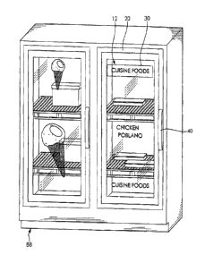
of site" challenges within the retail environment, they are limited in their
effective use.
Accordingly, there is a need in the art for improved digital display systems.
CA 02778462 2012-12-28
SUMMARY OF THE INVENTION
[0009] Disclosed are digital display systems and methods that overcome at
least one of the
disadvantages of the prior art described above. Disclosed is a digital display
system
comprising, in combination, a transparent outer protective panel, a
transparent inner protective
panel, and a translucent digital video display located between the outer and
inner protective
panels. An integrated media player operably connected to the translucent
digital video display
so that full-motion videos displayed on the translucent digital video display
are viewed through
the outer protective panel and items located behind the inner protective panel
can be viewed
through the translucent digital video display.
[0010] Also disclosed is a digital display system comprising, in combination,
a transparent
outer protective panel, a transparent inner protective panel, and a
translucent digital video
display located between the outer and inner protective panels, and a light
guide including a
glass panel secured to the translucent video display. The glass panel includes
micro-particles
therein for reflecting light. A light source is adjacent an edge of the glass
panel to provide light
within the glass panel that strikes the micro-particles and is reflected out
through the outer
protective panel. A media player is operably connected to the translucent
digital video display
so that full-motion videos displayed on the translucent digital video display
are viewed through
the outer protective panel and items located behind the inner protective panel
can be viewed
through the translucent digital video display.
[0011] Also disclosed is a digital display system comprising, in combination,
a transparent
outer protective panel, a transparent inner protective panel, a translucent
LCD video display
located between the outer and inner protective panels, and a light guide
including a glass panel
is adhered to the translucent LCD video display. The glass panel includes
micro-particles
therein for reflecting light. At least one LED adjacent is provided to provide
light within the
glass panel that strikes the micro-particles and is reflected out through the
outer protective
panel to provide visibly uniform illumination through the outer protective
panel at the LCD
video display. A media player operably connected to the translucent LCD video
display so that
2
CA 02778462 2012-12-28
high definition, color, full-motion videos displayed on the translucent LCD
video display are
viewed through the outer protective panel and items located behind the inner
protective panel
can be viewed through the translucent LCD video display. A frame encircles
peripheries of the
outer and inner protective panels and the translucent LCD video display and
the media player
are sealed within the frame and the outer and inner protective panels.
[0012] From the foregoing disclosure and the following more detailed
description of various
preferred embodiments it will be apparent to those skilled in the art that the
present invention
provides a significant advance in the technology and art of digital display
systems. Particularly
significant in this regard is the potential the invention affords for systems
and methods that
focus consumer attention in a desired manner without obstructing the
customer's line of site in a
cost effective manner. Additional features and advantages of various preferred
embodiments
will be better understood in view of the detailed description provided below.
BRIEF DESCRIPTION OF THE DRAWINGS
[0013] These and further features of the present invention will be apparent
with reference to
the following description and drawing, wherein:
[0014] FIG. 1 is a perspective view of a double glass-door upright cooler
incorporating a
translucent digital display system according to the present invention.
[0015] FIG. 2 is a perspective view of the upright cooler of FIG. 1, wherein
one of the glass-
doors is partially opened.
[0016] FIG. 3 is a diagrammatic view of one of the doors of the cooler of
FIGS. 1 and 2
showing components of the translucent digital display system.
[0017] FIG. 4 is an enlarged diagrammatic view showing a portion of the door
of FIG. 3in
the area of a removable media player.
3
CA 02778462 2012-12-28
100181 FIG. 5 is a diagrammatic view of a cross-section of door of FIG. 3
taken along line 5-
5.
[0019] FIG. 6 is a schematic view the digital display system of the cooler of
FIGS. 1 and 2
100201 FIG. 7 is a diagrammatic view similar to FIG. 18 but showing an
alternative
embodiment of the of translucent digital display system.
[0021] FIG. 8 is a perspective view of a double glass-door upright freezer
incorporating a
translucent digital display system according to another embodiment of the
present invention.
100221 FIG. 9 is a perspective view of a architectural glass window
incorporating a
translucent digital display system according to yet another embodiment of the
present
invention.
100231 It should be understood that the appended drawings are not necessarily
to scale,
presenting a somewhat simplified representation of various preferred features
illustrative of the
basic principles of the invention. The specific design features of the digital
display systems as
disclosed herein, including, for example, specific dimensions and shapes of
the various
components will be determined in part by the particular intended application
and use
environment. Certain features of the illustrated embodiments have been
enlarged or distorted
relative to others to facilitate visualization and clear understanding. In
particular, thin features
may be thickened, for example, for clarity or illustration. All references to
direction and
position, unless otherwise indicated, refer to the orientation of the digital
display systems
illustrated in the drawings.
4
CA 02778462 2012-12-28
DETAILED DESCRIPTION OF CERTAIN PREFERRED EMBODIMENTS
[0024] It will be apparent to those skilled in the art, that is, to those who
have knowledge or
experience in this area of technology, that many uses and design variations
are possible for the
improved digital display systems and methods disclosed herein. The following
detailed
discussion of various alternative and preferred embodiments will illustrate
the general
principles of the invention with regard to the specific application of glass
displays and
architectural glass. Other embodiments suitable for other applications will be
apparent to those
skilled in the art given the benefit of this disclosure.
[0025] FIGS. 1 and 2 illustrate a double glass-door upright cooler or chiller
10 having
translucent digital display systems 12 according to the present invention. The
illustrated cooler
has a interior space 14 which is cooled by a suitable refrigeration system to
keep product
displayed therein at a desired temperature. The illustrated interior space 14
is provided with a
plurality of shelves for holding product 18 thereon. The illustrated interior
space 14 is also
provided with a suitable light source for illuminating the interior space 14.
The illustrated
cooler 10 has two hinged doors 20 each provided with one of the translucent
digital display
systems 12 according to the present invention. It is noted that the cooler 10
can alternatively
have a fewer or greater number of doors 20 and/or less than all of the doors
20 can be provided
the translucent digital display systems12 . When the cooler 10 has more than
one translucent
digital display system 12 and/or there is more than one cooler 10, the
translucent digital display
systems 12 can be independent of one another or can interact together to
provide an "array"
experience for the consumer. Multiple cooler doors 20 can work together,
spanning a digital
image across 5, 10, or even 50 doors 20, and allowing consumer search on one
door 20 to
highlight product on another door 20, and allowing doors 20 to provide
interactive consumer
media in a large format as further described hereinbelow.
[0026] The illustrated cooler 10 has product or items 18 in the form of beer
located on the
shelves 16 within the cooled interior space 14 Additionally, a beer video
advertisement is
displayed on the translucent digital display systems 12 so that customers see
the advertisement
5
CA 02778462 2012-12-28
and can look straight through the advertisement on the translucent digital
display systems 12 to
see the product 18 on shelves 16 within the cooler 10 and behind the doors 20.
While the
illustrated digital display system 12 can display full motion video, it can
also display still
images, slide shows of still images, or any combination. To further engage
consumers, the
illustrated translucent digital display system 12 can display promotional
coupons, product
videos, social media interactions via 2D QR codes., and the like
[0027] As shown in FIGS. 3 to 6, the illustrated digital display system12 is
incorporated into
the cooler door 20 to form of the fully self-contained package such that it
only requires being in
electrical communication a power source 22 and wirelessly in data
communication with central
management server 24 to be fully functional. The illustrated translucent
digital display system
12 comprises, in combination, a transparent outer protective panel or sheet
26, a transparent
inner protective panel or sheet 28, a translucent digital video display 30
located between the
outer and inner protective panels 26, 28, and an integrated media player 32
operably
connected to the translucent digital video display 30 so that high definition,
full-color, full-
motion videos displayed on the translucent digital video display 30 are viewed
through the
outer protective panel 26 and items located behind the inner protective panel
28 can be viewed
through the translucent digital video display 30.
100281 The outer and inner protective panels 26, 28 preferably comprise glass
but any other
suitable material can alternatively be utilized. The illustrated cooler door
20 includes a single
outer protective panel 26 and a single inner protective layer 28, but it is
noted that there can
alternatively be more than one outer protective panel 26 and/or there can
alternatively be more
than one inner protective panel 28. The illustrated inner and outer protective
panels 26, 28 are
spaced apart to form a space 34 therebetween and a frame 36 encircles a
periphery of the outer
and inner protective panels 26, 28. The frame 36 encloses outer edges of the
protective panels
26, 28 and closes and seals the gap 34 between the protective panels 26, 28.
The frame 36 is
preferably formed of metal but can alternatively be formed of any other
suitable material. The
translucent digital video display 30 and all of the electronics associated
therewith (including the
6
CA 02778462 2012-12-28
media player 32) are located in the space or gap 34 between the inner and
outer protective
panels 26, 28 as described in more detail hereinafter. The gap 34 between the
protective panels
26, 28 is preferably filled with an inert gas such as, for example, argon. The
illustrated cooler
door 20 is also provided with suitable hinges 38 on one side and a handle 40
on the opposite
side but it is noted that the cooler door 20 can alternatively have any other
suitable
configuration.
[0029] The illustrated translucent digital video display 30 is an LCD video
display or panel
but any other suitable type of digital video display can alternatively be
utilized. The translucent
LCD video display can include liquid crystal optical films, in place of
traditional LCD
backlights. The translucent digital video display 30 is see-through in that it
can be gazed
through to the opposite side when the display 30 is powered on so that
products or items 18
located behind the translucent digital video display 30 can be seen through
the translucent
digital video display 30. Suitable translucent LCD video panels are available
from Samsung
and LG Electronics. The illustrated cooler door 20 has a single rectangular
translucent LCD
video panel that is sized smaller than the protective panels and is oriented
in a portrait direction
but it is noted that more than one translucent LCD video panel can
alternatively be utilized,
other suitable shapes, sizes and orientations of the translucent LCD video
panel can
alternatively be utilized, and/or the translucent LCD video panel can extend
entirely to the
frame 36.
[0030] The illustrated translucent digital video display 30 is located within
the sealed space
34 between the outer and inner protective panels 26, 28. The illustrated
translucent digital
video display 30 is supported within the space 34 by spacers 42 located at the
four sides of the
translucent digital video display 30 and extend from the frame 36 to position
and support the
translucent digital video display 30 within the space 34. It is noted that the
translucent digital
video display 30 can alternatively be supported in any other suitable manner.
The illustrated
door 20 is provided with shields 44 located within the protective panels 26,
28 to block the
view of the interior space 34 through the protective panels 26, 28 about the
translucent digital
7
CA 02778462 2012-12-28
video display 30. It is noted that when the translucent digital video display
30 extends to the
frame 36, the shields 44 are not required. It is also noted that the shields
44 can be integral
with and/or formed by the spacers 42. Also located within the sealed space 34
between the
outer and inner protective panels 26, 28 is a display panel power and signal
control board 46
operably connected to the translucent digital video display 30.
100311 The illustrated media player 32 is located within the sealed space 34
between the outer
and inner protective panels 26, 28 and has integrated memory and an integrated
wireless
communication system. The memory can be flash or solid state based storage and
the
communication system can be a wireless radio (for example, either 802.11 or
cellular 3G/4G)
with an embedded radio antenna. It is noted, however, that any other suitable
memory and/or
communication system can alternatively be utilized. For example, the wireless
connection can
be replaced with a hard wire connection. The media player 32 can include
single board
computer Media Player hardware with embedded storage (powered by, for example,
Intel Atom
or ARM based processors). Operating system software is provided on the media
player 32.
The operating system software can be a standard operating system such as, for
example,
Microsoft Windows or Linux. Application software is also provided on the media
player 32 to
receive media files, play media files and record play information for future
auditing of play
history. The application software can be a standard media player software such
as, for
example, ActiVia for Media TM available from STRATACACHE, Inc., of Dayton,
Ohio. The
illustrated media player 32 is connected to the power and signal control board
46 by a cable 48.
The cable 48 can be any suitable standard cable such as, for example, a HDMI
or LVDS cable.
100321 The illustrated digital display system 12 also includes a DC power bus
50 located
within the sealed space 34 between the outer and inner protective panels 26,
28. The DC power
bus 50 provides ongoing power to both the media player 32 and the power and
signal control
board 46 of the translucent digital video display 30. The DC power bus 50 is
electrically
connected with the media player 32 and power and signal control board 46 with
cables 52, 54.
The cables 52, 54 can be any suitable standard power cables. The DC power bus
50 is adapted
8
CA 02778462 2012-12-28
to receive power from the power source 22 in any suitable manner. The
illustrated DC power
bus 50 receives power from the power source 22 through a cable 56 extending
through the door
hinge 38 but any other suitable method can alternatively be utilized.
100331 As best shown in FIG. 4, the illustrated media player 32 includes a
base or receiver
portion 58 having a slot and a removable portion 60 which is insertable into
and removable
from the slot so that it is easily serviceable. The fixed cable connections
with the DC power
bus 50 and the power and signal control board 46 of the translucent digital
video display 30 are
each to the base portion 58 while all the electronics (memory, radio, etc.)
are located within the
removable portion 60. The illustrated frame 36 includes a removable door 62 to
access the
removable media player 60. It is noted that the base portion 58 is adequately
secured and
sealed to the frame 36 so that accessing the removable media player 60 does
not affect the
sealed interior space 34 of the door 20. This "slotted" media player
architecture allows the
media player 60 to slide into the slot connected or proximate to the
translucent digital video
display 30 with the permanent connection cable 48 from the slotted "receiver"
interface 58 to
the power and signal control board 46 of the translucent digital video display
30. This
removability allows the media player to be easily serviced and
replaced/upgraded. The
inclusion of the wireless radio into the media player 32 prevents an external
cable, such as an
Ethernet cable, connection from being required to communicate with the media
player 32 and
allows the wireless radio to also be easily serviced and replaced/upgraded.
[0034] It is noted that the illustrate translucent display system 12 in the
form of a cooler door
20 is a fully self-contained package. The intelligent media player 32 being
built within the
enclosure allows the media player 32 to be self contained within the door 20
with no external
cables, media player interface, or other device requiring cable connectivity
back into the sealed
door 20. In other applications, the self-contained packaging eliminates the
need for secondary
cables to connect to the unit to provide network connectivity. The only
connection required is
a single connection to the power source 22.
9
CA 02778462 2012-12-28
[0035] As best shown in FIGS. 3 and 6, audio speakers 64 can be provided
within the interior
space 34 if desired to provide audio for the videos on the translucent digital
video display 30.
The illustrated speakers 64 are provided in the frame 36 at the bottom of the
door 20. The
illustrated speakers 64 are connected to the media player 32 by cables but any
other suitable
connection can alternatively be provided.
[0036] As best shown in FIGS. 3 and 6, an infrared sensor or touch detection
system 68 can
be provided if desired to provide touch interactivity with the translucent
digital video display
30. The illustrated infrared touch detection system 68 is built into the door
surround of the
frame 36 but any other suitable configuration can alternatively be utilized.
The system 68 is
operably connected to the media player 32 by a suitable cable 70 or the like.
The sensor or
touch detection system 68 allows a consumer to interact with the content or
application running
on the digital video display 30 via a touch interface. The touch interface
system 68 can allow a
customer to perform search functions on a specific door for product, recipe,
coupon or other
consumer enticements. It is noted that any other suitable touch interface
system 68 such as, for
example, a touch pad or key pad, can alternatively be utilized.
[0037] As best shown in FIGS. 3 and 6, a consumer facing camera 72 can
alternatively be
provided if desired to provide motion interactivity with the translucent
digital video display 30.
The illustrated camera 72 is located at the frame 36 at the top of the door 20
so that it looks
down on customers but any other suitable configuration can alternatively be
utilized. The
consumer facing camera 72 can be a micro USB camera or the like and operably
connected to
the media player 32 by a suitable cable 74 or the like. The camera interface
system 72 allows a
consumer to interact with the content or application running on the digital
video display 30 via
motion such as, for example, waving hands or the like. The camera motion
interface 72 can
allow a customer to perform search functions on a specific door for product,
recipe, coupon or
other consumer enticements. Audience measurement software or the like can be
run by the
media player 32 and can be, for example, Audience Measurement available from
CA 02778462 2012-12-28
STRATACACHE, Inc., of Dayton, Ohio. It is noted that any other suitable motion
interface
72 can alternatively be utilized.
[0038] Under conditions where there are multiple items 18 behind the
translucent digital
video display 30, the items 18 can block light from passing though the
translucent digital video
display 30 such that it is difficult to view. Particularly when the items 18
are dark or black.
This problem can be solved by providing a light source 76 along with a light
guide 78 to
provide light between the product 18 and the translucent digital video display
30. As best
shown in FIG. 7, the translucent digital video display 30 can be secured to
the light guide 78 in
the form of transparent specialty glass panel or plate 80 with the light
source providing light to
at least one edge of the glass plate 80. The glass plate 80 is provided with
embedded micro-
particles 82 that reflect light out the faces of the glass plate 80. Suitable
glass plates 80 are
available from Corning Inc. The illustrated light source 76 is at least one
LED but any other
suitable light 76 source can alternatively be utilized. The light source 76
can be connected to
the DC bus 50 for power by a power cable and/or to the media player 32.
[0039] The translucent digital video display 30 is preferably chemically
bonded to the
specialty glass plate 80 using a suitable chemical bonding agent 84 in a
vacuum chamber
within a clean room environment. Prior to the chemical bonding, preparation of
the glass plate
80 includes polishing all edge surfaces of the glass plate 80, the application
of a reflective film
or tape 86 to the edges of the glass plate 80 to reflect light inward toward
the center of the glass
plate 80. Once the translucent digital video display30 is bonded to the glass
plate 80, the edge
light source 76 is attached (outside of the viewing surface) which allows
light to be carried
through the glass plate 80 and evenly or uniformly distributed towards the
viewer through the
outer protective panel 26 as the light is reflected out the face of the glass
panel 80 when it
strikes the micro-particles 82. Thus, additional light is directed through the
translucent digital
video display 30 to add directed light to the consumer's experience without
the consumer seeing
the origin point of the additional light or blocking the consumer's view of
the product 18 behind
the translucent digital video display 30.
11
CA 02778462 2012-12-28
[0040] FIG. 8 illustrates a double glass-door upright freezer 88 having the
translucent digital
display system 12 according to the present invention. The illustrated upright
freezer 88 shows
that the translucent display system 12 can be incorporated into other types of
product displays
having product viewable through glass panels. The illustrated freezer 88 is
substantially the
same as the cooler 12 described hereinabove except the freezer 88 is designed
for frozen
product 18 rather than chilled product 18 like the above described cooler 10.
The illustrated
freezer 88 shows that a frozen food advertisements can be displayed on the
translucent digital
video displays 30 so that customers see the advertisements and can look
straight through the
advertisements on the translucent digital video displays 30to see frozen food
product 18 on
shelves 16 within the freezer 88 and behind the doors 20.
[0041] FIG. 9 illustrates an architectural window 90 having a translucent
digital display
system 12 according to the present invention. The illustrated window 90 shows
that the
translucent digital display system 12 can be incorporated into fixed
architectural glass
assemblies such as windows, doors, and the like. The illustrated window 90 is
substantially the
same as the cooler doors 20 described hereinabove except that it is adapted to
be a fixed display
window 90 rather than a display door 20. The illustrated window 90 shows that
a stationary
advertisement can be displayed on the translucent digital video display 30 so
that customers see
the advertisement and can look straight through the advertisement on the
translucent digital
video display 30 to see consumer goods 18 located behind the window 90.
[0042] From the foregoing disclosure it will be apparent that the translucent
digital display
systems 12 according to the present invention can incorporated into any glass
enclosure such
as, for example, product display cases like freezers, coolers, jewelry cases,
liquor cases,
cosmetic cases, and the like or architectural glass like entry doors, windows,
drive-thru
windows, teller windows, and the like.
12
CA 02778462 2012-12-28
100431 Any of the features or attributes of the above described embodiments
and variations
can be used in combination with any of the other features and attributes of
the above described
embodiments and variations as desired.
[0044] From the foregoing disclosure and detailed description of certain
preferred
embodiments, it will be apparent that various modifications, additions and
other alternative
embodiments are possible without departing from the true scope of the present
invention. The
embodiments discussed were chosen and described to provide the best
illustration of the
principles of the present invention and its practical application to thereby
enable one of
ordinary skill in the art to utilize the invention in various embodiments and
with various
modifications as are suited to the particular use contemplated. All such
modifications and
variations are within the scope of the present invention as determined by the
appended claims.
13