Note: Descriptions are shown in the official language in which they were submitted.
CA 02778514 2012-05-29
SURGICAL INSTRUMENT AND
CARTRIDGE FOR USE THEREWITH
BACKGROUND
Technical field
[0001] The present disclosure relates generally to instruments for surgically
joining tissue and, more specifically, to a surgical instrument that can be
fired more than
once without being required to reload fasteners.
Background of Related Art
[0002] Various types of surgical instruments used to surgically join tissue
are
known in the art, and are commonly used, for example, for closure of tissue or
organs in
transection, resection, anastomoses, for occlusion of organs in thoracic and
abdominal
procedures, and for electrosurgically fusing or sealing tissue.
[0003] One example of such a surgical instrument is a surgical stapling
instrument, which may include an anvil assembly, a cartridge assembly for
supporting an
array of surgical fasteners, an approximation mechanism for approximating the
cartridge
and anvil assemblies, and a firing mechanism for ejecting the surgical
fasteners from the
cartridge assembly.
[0004] Using a surgical instrument, it is common for a surgeon to approximate
the anvil and cartridge members. Next, the surgeon can fire the instrument to
emplace
fasteners in tissue. Additionally, the surgeon may use the same instrument or
a separate
instrument to cut the tissue adjacent or between the row(s) of fasteners.
1
CA 02778514 2012-05-29
[0005] Additionally, a single use loading ("SULU") or a disposable loading
unit
("DLU") may be attached to an elongated or endoscopic portion of a surgical
stapling
instrument. Such loading units allow surgical stapling instruments to have
greater
versatility, for example. The loading units may be configured for a single
use, and/or
may be configured to be used more than once.
[0006] Further, surgical instruments and/or loading units may include a
cartridge
that is removable and replaceable. For example, after all of the fasteners in
a first
cartridge have been ejected, a user may remove the first cartridge and replace
it with a
second cartridge including fasteners.
SUMMARY
[0007] The present disclosure relates to a cartridge assembly for use with a
surgical instrument. The cartridge assembly comprises a cartridge housing and
a
cartridge. The cartridge housing has a plurality of biasing members thereon.
The
cartridge is configured for reception at least partially within the cartridge
housing. The
cartridge includes a plurality of fasteners at least partially therein. The
cartridge has a
plurality of pockets. Each fastener is ejectable from a corresponding pocket.
The
cartridge has a plurality of chambers therein, and each chamber is adjacent a
pocket and
is configured to store at least one fastener at least partially therein. At
least one fastener
is movable from the chamber to the pocket. The cartridge includes a plurality
of pushers,
where each pusher is configured to engage at least one corresponding fastener.
At least
one pusher includes at least one cam surface thereon. Each biasing member
urges at least
one corresponding fastener toward the corresponding pocket.
2
CA 02778514 2012-05-29
[00081 The present disclosure also relates to a loading unit configured for
engagement with a surgical instrument. The loading unit comprising a proximal
body
portion defining a longitudinal axis, a tool assembly disposed in mechanical
cooperation
with the proximal body portion, and a cartridge assembly disposed in
mechanical
cooperation with the tool assembly. The cartridge assembly comprises a
cartridge
housing, a cartridge, and a driver. The cartridge housing has a plurality of
biasing
members thereon. The cartridge is configured for reception at least partially
within the
cartridge housing and includes a plurality of fasteners at least partially
therein. The
cartridge has a plurality of pockets, with each fastener being ejectable from
a
corresponding pocket. The cartridge has a plurality of chambers therein, and
each
chamber is adjacent a pocket and is configured to store at least one fastener
at least
partially therein. At least one fastener is movable from the chamber to the
pocket. The
cartridge also includes a plurality of pushers, and each pusher is configured
to engage a
corresponding fastener. Each biasing member urges at least one corresponding
fastener
toward the corresponding pocket. The driver is disposed in mechanical
cooperation with
the cartridge assembly, and is movable substantially parallel to the
longitudinal axis into
engagement with the pushers.
[00091 The present disclosure also relates to a surgical instrument comprising
a
handle assembly, a firing rod, an endoscopic portion, and a cartridge
assembly. The
handle assembly includes a movable handle. The firing rod is disposed in
mechanical
cooperation with the movable handle. The endoscopic portion extends distally
from the
handle assembly. The cartridge assembly is disposed adjacent a distal end of
the
endoscopic portion and comprises a cartridge housing, a cartridge, and a
plurality of
3
CA 02778514 2012-05-29
pushers. The cartridge housing has a plurality of biasing members. The
cartridge is
configured for reception at least partially within the cartridge housing. The
cartridge
includes a plurality of fasteners at least partially therein. The cartridge
has a plurality of
pockets. Each fastener is ejectable from a corresponding pocket. The cartridge
has a
plurality of chambers therein, and each chamber is adjacent a pocket and is
configured to
store at least one fastener at least partially therein. At least one fastener
is movable from
the chamber to the corresponding pocket. Each of the plurality of pushers is
configured
to engage a corresponding fastener. Each biasing member urges at least one
corresponding fastener toward the corresponding pocket. Distal advancement of
the
firing rod causes sequential ejection of at least some of the fasteners.
[00101 The present disclosure also relates to a surgical stapling instrument
comprising a cartridge assembly and an anvil assembly. The cartridge assembly
has a
cartridge body, a plurality of pushers supporting a plurality of fasteners in
the cartridge
body, and a driver longitudinally movable through the cartridge body in distal
and
proximal directions. The pushers have first cam surfaces and second cam
surfaces. The
anvil assembly has fastener forming surfaces. The driver has an upper portion
and a
lower portion. The upper portion of the driver contacts the second cam
surfaces
sequentially when the driver is moved in the proximal direction. The lower
portion of
driver contacts the first cam surfaces when the driver is moved in the distal
direction.
4
CA 02778514 2012-05-29
BRIEF DESCRIPTION OF FIGURES
[0011] Various embodiments of the presently disclosed surgical instruments and
loading units are disclosed herein with reference to the drawings, wherein:
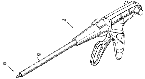
[0012] Figure IA is a perspective view of a surgical instrument in accordance
with the present disclosure;
[0013] Figure lB is a perspective view of another surgical instrument in
accordance with the present disclosure;
[0014] Figure 2 is a perspective view of a handle portion of the stapling
instruments of Figures IA and 1B;
[0015] Figure 3 is a perspective view of a distal portion of the handle
portion of
Figure 2;
[0016] Figure 4 is a perspective view of a loading unit of the surgical
instruments
of Figures IA and 113;
[0017] Figures 5 is a perspective exploded view of a clamping member and
drivers of the surgical instruments of Figures IA and 113;
[0018] Figure 6 is a perspective view of a portion of a cartridge assembly of
the
surgical instrument of the present disclosure;
[0019] Figure 7 is a perspective view of a portion of a cartridge housing of
the
cartridge assembly of Figure 6;
[0020] Figure 8 is a perspective view of a portion of a cartridge, a plate and
fasteners of the cartridge assembly of Figure 6;
[0021] Figure 9 is a perspective view of a pusher and fasteners of the
cartridge
assembly of Figure 6;
CA 02778514 2012-05-29
[0022] Figure 10 is a transverse cross-sectional view of a portion of the
cartridge
assembly of Figure 6 including a plurality of fasteners therein;
[0023] Figure 11 is a transverse cross-sectional view of a portion of the
cartridge
assembly of Figure 6 including no fasteners therein;
[0024] Figure 12 is a perspective view of a portion of a driver of Figure 5;
[0025] Figure 13 is a longitudinal cross-sectional view of a portion of the
cartridge assembly of Figure 6 in combination with a portion of a driver; and
[0026] Figure 14 is a transverse cross-sectional view of a tool assembly,
including
an anvil and a cartridge channel, and including two cartridge assemblies, two
drivers, and
the clamping member.
DETAILED DESCRIPTION
[0027] Embodiments of the presently disclosed surgical instrument, loading
unit
for use therewith, and cartridge assembly for use therewith, are described in
detail with
reference to the drawings, wherein like reference numerals designate
corresponding
elements in each of the several views. As is common in the art, the term
"proximal"
refers to that part or component closer to the user or operator, e.g., surgeon
or physician,
while the term "distal" refers to that part or component farther away from the
user.
[0028] A surgical instrument having linear jaw members of the present
disclosure
is indicated as reference numeral 100a in Figure 1A. A surgical instrument
having
curved jaw members of the present disclosure is indicated as reference numeral
100b in
Figure 1B. Collectively, surgical instruments 100a and 100b are referred to
herein as
reference numeral 100. Similarly, several features that are common to both
surgical
6
CA 02778514 2012-05-29
stapling instruments 100a and 100b are collectively referred to as the same
reference
number (e.g., handle portion 110, endoscopic portion 120, and jaw members
230).
[0029] Handle portion 110 of surgical instrument 100 is shown in FIG. 2, and
an
enlarged view of the distal end of handle portion 110, including a distal end
of firing rod
130, is shown in FIG. 3. A single use loading unit ("SULU") or a disposable
loading unit
("DLU") (collectively referred to as "loading unit 200"), which is
mechanically
engageable with handle portion 100 is shown in Figure 4. Loading unit 200 is
attachable
to endoscopic portion 120 of surgical stapling instrument 100, e.g., to allow
surgical
instrument 100 to have greater versatility. Loading unit 200 may be configured
for a
single use, and/or may be configured to be used more than once. Alternatively,
a
surgical instrument may have a cartridge which is removable and replaceable in
the
reusable jaws of the instrument.
[0030] Examples of loading units for use with a surgical stapling instrument
are
disclosed in commonly-owned United States Patent No. 5,752,644 to Bolanos et
al., the
entire contents of which are hereby incorporated by reference herein. Further
details of
an endoscopic surgical stapling instrument are described in detail in commonly-
owned
U.S. Patent No. 6,953,139 to Milliman et al., the entire contents of which are
hereby
incorporated by reference herein.
[0031] In a surgical instrument 100 in accordance with the present disclosure,
a
firing rod 130 is moved distally through actuation of a movable handle 132 to
deploy the
fasteners. For example, referring back to Figures 1A and 1B, at least a
partial actuation
of movable handle 132 with respect a stationary handle 134 translates firing
rod 130
longitudinally, such that a dynamic clamping member 240, its associated bar
250, and a
7
CA 02778514 2012-05-29
proximal block 260 (e.g., Figure 5) translates longitudinally, to approximate
at least one
jaw member with respect to the other. It is also envisioned that other types
of handles
can be used such as, for example, motor-driven, hydraulic, ratcheting, etc.
[0032] In the embodiment illustrated in FIG. 14, dynamic clamping member 240
includes an I-shaped cross-section, the top portion of which is configured to
engage the
anvil assembly, and the bottom portion of which is configured to engage the
cartridge
assembly. More particularly, engagement between the top portion of the dynamic
clamping member 240 and the anvil assembly causes the anvil assembly to pivot
towards
the cartridge assembly, e.g., to clamp tissue therebetween. Continued distal
translation of
the dynamic clamping member 240 helps maintain the relative positions of the
cartridge
assembly and the anvil assembly with respect to each other.
[0033] Additionally, upon distal advancement, dynamic clamping member 240
advances drivers 820 through cartridge assembly 222. As the drivers 820 move
distally,
each driver 820 sequentially engages a plurality of pushers, and causes the
pushers to
move vertically within the cartridge assembly and eject fasteners 760 towards
the anvil.
The dynamic clamping member 240 may include a cutting edge 242 on a distal
face of
dynamic clamping member 240 to sever the stapled tissue. Subsequent to the
ejection of
fasteners 760, the stapled tissue is cut by the cutting edge 242 of the
dynamic clamping
member 240.
[0034] With reference to Figure 4, loading unit 200 of the present disclosure
is
shown. Loading unit 200 includes a proximal body portion 210 defining a
longitudinal
axis "A-A," and a tool assembly 220 including a pair of jaw members 230.
Proximal
body portion 210 is configured to removably attach to endoscopic portion 120
of surgical
8
CA 02778514 2012-05-29
instrument 100. More particularly, an insertion tip 202 of loading unit 200 is
linearly
inserted into the distal end of endoscopic portion 120 (Figures 2 and 3) of
surgical
stapling instrument 100. Nubs 204 of insertion tip 202 (Figure 4) move
linearly through
slots (not shown) formed in the distal end of endoscopic portion 120.
Subsequently,
loading unit 200 is rotated about the longitudinal axis "A-A" such that nubs
204 move
transversely through slots (not shown) within endoscopic portion 120.
Additionally,
during engagement of loading unit 200 and endoscopic portion 120, firing rod
130 of
handle portion 110 engages dynamic clamping member 240 of loading unit 200
(see FIG.
5).
[00351 With reference to Figures 6-14, jaw members 230 of loading unit 200
include an anvil assembly 600 and a cartridge channel 700. In the illustrated
embodiments, cartridge channel 700 houses a first cartridge assembly 710a and
a second
cartridge assembly 710b (collectively referred to as cartridge assembly 710),
and includes
a track 712 therebetween. Each cartridge assembly 710 includes a cartridge
housing 720,
a cartridge or cartridge body 740, a plurality of fasteners 760, a plurality
of plates 780,
and a plurality of pushers 800.
[0036] With particular reference to Figure 7, each cartridge assembly 710a,
710b
has a cartridge housing 720. One such cartridge housing 720 is shown.
Cartridge
housing 720 includes a plurality of biasing members 722 (e.g., leaf springs)
thereon.
Biasing members 722 are flexible fingers disposed on each side of the
cartridge housing
710 and that are biased towards opposite side cartridge housing 720 (as shown
in FIG. 7).
Biasing members 722 are configured such that they are able to be against their
bias into
substantial alignment with an external wall 724 of cartridge housing 720 (see,
for
9
CA 02778514 2012-05-29
example, FIG. 10). As discussed below, each biasing member 722 is configured
to bias a
plate, and corresponding fasteners toward the opposite side of cartridge
housing 720.
[0037] Referring now to FIGS. 8-11, cartridge or cartridge body 740, and
components thereof, are illustrated. Cartridge or cartridge body 740 is
configured for
reception at least partially within cartridge housing 720 (FIG. 7) (e.g., a
snap-fit
connection) and includes a plurality of pockets 742, and a plurality of
chambers 744
(FIG. 11). Each pocket 742 extends through a tissue-contacting surface 750 of
cartridge
body 740, and is configured to releasably store a fastener 760 that is ready
to be fired.
Each chamber 744 is adjacent a corresponding pocket 742 and is configured to
store
fasteners 760 therein (e.g., two fasteners 760). The configuration of pockets
742 and
chambers 744 allows fasteners to move from chamber 744 to pocket 742 in
response to
the biasing force supplied by biasing members 722. An internal wall 746 of
cartridge
body 740 is adjacent pockets 742 and resists the biasing force, such that
fasteners 760 do
not get pushed beyond pocket 742.
[0038] With reference to FIGS. 6, 8, 10 and 11, plurality of plates 780 are
shown.
Plates 780 are disposed on the opposite side of chamber 744 than pockets 742.
When
fasteners 760 are present in cartridge body 740 (see FIG. 10), each plate 780
is between
biasing member 722 and fastener 760. When no fasteners 760 are present in
cartridge
body 740 (e.g., after each fastener 760 has been fired; see FIG. 11), each
plate 780 is
between biasing member 722 and internal wall 746 (e.g., at least partially
within pocket
742). Additionally, when no fasteners 760 are present in cartridge body 740,
plates 780
block the path for advancement of pushers 800, thus preventing a user from
firing/attempting to fire with an empty cartridge body 740. Plates 780 are
sized to
CA 02778514 2012-05-29
facilitate sliding within chamber 744 toward pocket 742. Additionally, and as
shown in
the embodiment illustrated in FIG. 8, plates 780 include a cut-out portion or
indentation
782, which is sized to facilitate engagement with biasing member 722.
[0039] With particular reference to FIGS. 9-13, a plurality of pushers 800 and
a
plurality of fasteners 760 are shown. Each pusher 800 includes a central
portion 802 and
a pair of lateral portions 804a, 804b. Central portion 802 includes a first
cam surface 806
and a second cam surface 808. As discussed below, each cam surface 806, 808 is
configured to be engaged by a driver 820 to move pusher 800 toward and away
from
tissue-contacting surface 750 of cartridge body 740. Each lateral portions
804a, 804b is
configured to engage a fastener 760, such that movement of pusher 800 toward
tissue-
contacting surface 750 of cartridge body 740 causes corresponding fasteners
760 to be
ejected from cartridge body 740. In the illustrated embodiments, an upper
surface 805 of
lateral portions 804 includes a groove thereon (see FIGS. 9 and 10) to
facilitate
engagement with fastener 760.
[0040] Referring now to FIGS. 12-14 driver 820 is shown. Driver 820 is an
elongated member that is configured to move longitudinally through a passage
741
(FIGS. 10 and 11) in cartridge body 740 in response to actuation of movable
handle 132,
for example. Driver 820 includes a slot 822 therein which separates an upper
portion 823
from a lower portion 825. The slot 822 which extends proximally from a
location
adjacent a distal end thereof. Slot 822 includes a firing cam surface 824 and
a retraction
cam surface 826. Upon distal advancement of driver 820, firing cam surface 824
contacts
first cam surface 806 of pusher 800, which causes pusher 800 to move toward
tissue-
contacting surface 750 (FIG. 13). Further movement of the driver 820 causes
sequential
11
CA 02778514 2012-05-29
ejection of the fasteners 760. Proximal movement of driver 820 causes
retraction cam
surface 826 to contact second cam surface 808 of pusher 800, which causes the
pusher
800 to move away from tissue-contacting surface 750 (see FIG. 13). Further
such
movement of the driver 820 causes sequential retraction of the fasteners 760.
Additionally, in the embodiment illustrated in FIG. 5, the driver 820 is
rigidly attached to
dynamic clamping member 240.
[0041] In use, actuation of movable handle 132 causes distal translation of
dynamic clamping member 240, which causes distal translation of drivers 820.
As
drivers 820 advance distally, firing cam surfaces 824 of drivers 820 contact
first cam
surfaces 824 of pushers 800, which causes pushers 800 move toward tissue-
contacting
surface 750 of cartridge body 740. As shown in FIG. 13, pushers 800
sequentially move
toward tissue-contacting surface 750 (i.e., the proximal-most pusher moves
first,
followed by the distally-adjacent pusher, etc.). Movement of pushers 800
toward tissue-
contacting surface 750 causes corresponding fasteners 760 to be sequentially
ejected
from cartridge body 740. Here, after pushers 800 are elevated and within slots
822 of
drivers 820, pushers 800 resist the force of corresponding biasing members
722, and thus
prevent another fastener 760 from entering pockets 742 (i.e., the fasteners
760 remain in
chambers 744). As the driver 820 is distally advancing and the fasteners 760
are being
ejected from cartridge 710, a cutting element 242 (FIG. 14) of dynamic
clamping
member 240 cuts tissue between the jaw members 230.
[0042] After the driver 820 has been advanced a predetermined amount (e.g.,
corresponding to when all fasteners 760 have been ejected), a user may retract
dynamic
clamping member 240, and thus the driver 820. More than one driver 820 is
12
CA 02778514 2012-05-29
contemplated herein. Retraction of driver or drivers 820 causes retracting cam
surfaces
826 to contact second cam surfaces 808 of pushers 800, which causes pushers
800 to
sequentially move away from tissue-contacting surface 750 of cartridge body
740. After
pushers 800 have been moved away from tissue-contacting surface 750, pushers
800 no
longer resist the force of corresponding biasing members 722, and thus biasing
members
722 force another fastener 760 from chamber 744 into pocket 742.
[0043] Once drivers 820 have been retracted a predetermined amount (e.g.,
corresponding to when proximal-most fasteners 760 have been urged form
chambers 744
into pockets 742), a user may repeat the process of advancing and retracting
dynamic
clamping member 240 and drivers 820 to eject another set of fasteners 760
without the
need to replace cartridge channel 700 or cartridge assemblies 710. After all
of the
fasteners have been ejected from the cartridge assemblies, the plates 780
block the drivers
from being advanced, and the clamping member 240 from being advanced, to
prevent the
firing of an empty cartridge.
[0044] The illustrated embodiments illustrate three fasteners 760 in each
pocket
742/chamber 744, but it is envisioned and within the scope of the present
disclosure to
include more or fewer fasteners 760 therein. It is also envisioned that at
least one
fastener 760 of cartridge assembly 710 is a different size from other
fasteners 760. For
example, it is envisioned that the inner row of fasteners (i.e., initially
within pockets 742)
includes fasteners having legs of a longest length, and that the outer row of
fasteners
includes fasteners having legs of a shortest length, or vice versa. Here, it
is envisioned
that the pushers 800 are sized accordingly.
13
CA 02778514 2012-05-29
[0045] The present disclosure also includes a method of firing a set of
fasteners
from a cartridge assembly, and then firing another set of fasteners from the
same
cartridge assembly without the need to remove and/or replace the cartridge
assembly.
[0046] The present disclosure also includes embodiments having other types of
handles than the illustrated embodiment. For example, the present disclosure
also
includes a powered (e.g., electrically-powered, battery-powered, etc.) handle.
[0047] While the above description contains many specifics, these specifics
should not be construed as limitations on the scope of the present disclosure,
but merely
as illustrations of various embodiments thereof. Therefore, the above
description should
not be construed as limiting, but merely as exemplifications of various
embodiments.
Those skilled in the art will envision other modifications within the scope
and spirit of
the claims appended hereto.
14