Note: Descriptions are shown in the official language in which they were submitted.
CA 02778621 2012-05-30
Attorney Docket No.: 2012P01623US
1
HOME APPLIANCE WITH SUPPORT ASSEMBLY
Background of The Invention
[0001] The present invention relates broadly to floor-standing home appliances
and, more
particularly, to a home appliance, in the nature of a range, having a two-
piece support assembly.
[0002]Ranges are generally box-like, floor-standing appliances that include
some form of
leg support mounted at four corners of the range body. In whatever form, such
support should be
adjustable so that the height of the range can be varied for appearance and
leveling purposes. To
that end, some ranges include threaded apertures in the range frame for
receiving threaded
cylinders that can support the range on a floor and may be rotated in and out
of the apertures to
adjust the height of the range.
[0003] Some ranges are also relatively heavy, weighing more than five hundred
(500)
pounds. Such weight concentration, on the average of one hundred twenty five
(125) pounds per
corner, presuming even distribution of weight, can cause difficulties for
using threaded cylinders,
such as bolts, for support legs. In general, a bolt will be strong enough to
support the weight of
the range. However, the bolt head presents a small footprint and therefore a
high concentration of
weight in the form of pressure on the support surface, usually a kitchen
floor, which can be
damaging to the floor.
[0004] Accordingly, feet or shoes have been applied to threaded cylindrical
members to
make support legs for ranges. Such custom leg structures can be unnecessarily
expensive to
manufacture and use.
[0005] There accordingly exists a need for a support leg assembly that can use
a standard
bolt and still provide a shoe or foot with a sufficiently large footprint to
effectively distribute the
weight of a heavy range.
CA 02778621 2016-09-26
50777-289
2
Summary of the Invention
[0006] It is accordingly an object of the present invention to provide a
support leg
assembly that uses a standard bolt for the support leg with a dedicated shoe
that attaches
readily to the standard bolt.
[0007] It is another object to the present invention to provide such a leg
support
assembly that will distribute the weight of the range effectively.
[0008] To those ends, a floor-standing home appliance includes an appliance
body and
a support assembly for supporting the appliance body on a support surface. The
support
assembly includes a support member extending away from the appliance body with
the
support member having an engagement member with a predetermined shape at a
distal end
thereof. A shoe is attached to the distal end of the support member, with the
shoe having a
receiving well with a shape complimentary to the predetermined shape of the
engagement
member to receive the engagement member in the receiving well.
[0008a] According to one aspect of the present invention, there is provided a
floor-
standing home appliance comprising: an appliance body; and a support assembly
for
supporting the appliance body on a support surface, the support assembly
including: a
threaded support member extending away from the appliance body, the support
member
having a shaft and an engagement member having a predetermined shape with a
multi-faceted
distal end, with the shaft threads extending from the appliance body to the
distal end; and a
shoe attached to the distal end of the support member, the shoe having a
generally planar
platform with a multi-faceted wall projecting upwardly from the platform
terminating in a
planar rim and defining a receiving well having a floor and inner wall
surfaces, the inner wall
surfaces being formed with a multi-faceted shape complimentary to the
predetermined shape
of the engagement member, with the receiving well having an open top portion
larger than the
engagement member and configured to receive the engagement member in the
receiving well
with the engagement member in contact with the inner walls and floor of the
receiving well,
CA 02778621 2016-09-26
,
,
50777-289
2a
wherein the shoe and support member are configured to preclude relative
movement
therebetween.
10008b1 According to another aspect of the present invention, there is
provided a
floor-standing range comprising: a range body; and a support assembly for
supporting the
range body on a support surface, the support assembly including: a threaded
support member
extending away from the appliance body, the support member having a shaft and
an
engagement member having a predetermined shape with a multi-faceted distal
end, with the
shaft threads extending from the appliance body to the distal end; and a shoe
attached to the
distal end of the support member, the shoe having a generally planar platform
with a multi-
faceted wall projecting upwardly from the platform terminating in a planar rim
and defining a
receiving well having a floor and inner wall surfaces, the inner wall surfaces
being formed
with a multi-faceted shape complimentary to the predetermined shape of the
engagement
member, with the receiving well having an open top portion larger than the
engagement
member and configured to receive the engagement member in the receiving well
with the
engagement member in contact with the inner walls and floor of the receiving
well, wherein
the shoe and support member are configured to preclude relative movement
therebetween.
[0008cl According to still another aspect of the present invention, there is
provided a
floor-standing home appliance comprising: an appliance body; and a support
assembly for
supporting the appliance body on a support surface, the support assembly
including: a
threaded support member extending away from the appliance body, the support
member
having a shaft and an engagement member having a predetermined shape with a
multi-faceted
distal end, with the shaft threads extending from the appliance body to the
distal end; a shoe
attached to the distal end of the support member, the shoe having a generally
planar platform
with a multi-faceted wall projecting upwardly from the platform defining a
receiving well
with a multi-faceted shape complimentary to the predetermined shape of the
engagement
member, with the receiving well having an open top portion configured to
receive the
engagement member in the receiving well, wherein the shoe and support member
are
configured to preclude relative movement therebetween; and a generally planar,
one-piece
CA 02778621 2016-09-26
50777-289
2b
collar attached to the shoe to retain the engagement member in the receiving
well wherein the
collar abuts the wall forming the receiving well without abutting the shaft.
[0009] Preferably, the support member is a threaded cylinder threadedly
attached to
the appliance body whereby rotation of the support member changes the distance
of the
appliance body from the support surface and thereby the overall height of the
appliance.
[0010] It is preferred that the shoe includes a base and an upstanding wall,
with the
wall defining the receiving well.
[0011] The present invention further preferably includes a collar attached to
the shoe to
retain the engagement member in the receiving well. It is also preferred that
the wall defines a
threaded cavity and the collar is attached to the shoe using a screw abutting
the collar and
threadedly received in the threaded cavity. Preferably, the wall defines an
opposing pair of
CA 02778621 2012-05-30
Attorney Docket No.: 2012P01623US
3
threaded cavities and the collar is attached to the shoe using a pair of
screws abutting the collar
with one screw threadedly received in each of the threaded cavities.
[0012] It is preferred that the shoe is configured to provide at least one
square inch of
support surface contact area for each fifty (50) pounds of appliance weight.
[0013] Preferably, the engagement member has a hexagonal shape and the
receiving well
of the shoe has a complimentary hexagonal shape for receiving the engagement
member therein.
[0014] It is also preferred that the home appliance includes a support
assembly mounted
at each of four corners of the appliance body.
[0015] The present invention is also directed to a range. In that regard, a
floor-standing
range includes a range body and a support assembly for supporting the range
body on a support
surface. The support assembly includes a support member extending away from
the range body,
with the support member having an engagement member with a predetermined shape
at a distal
end thereof. Further, a shoe is attached to the distal end of the support
member. The shoe has a
receiving well with a shape complimentary to the predetermined shape of the
engagement
member to receive the engagement member in the receiving well.
[0016] It is preferred that the support member is a threaded cylinder
threadedly attached
to the range body whereby rotation of the support member changes the distance
of the range
body from the support surface and thereby the overall height of the range.
[0017] Preferably, the shoe includes a base and an upstanding wall, with the
wall defining
the receiving well.
[0018] The present invention further preferably includes a collar attached to
the shoe to
retain the engagement member in the receiving well. It is preferred that the
wall defines a
CA 02778621 2012-05-30
Attorney Docket No.: 2012P01623US
4
threaded cavity and the collar is attached to the shoe using a screw abutting
the collar and
threadedly received in the threaded cavity. Preferably, the wall defines an
opposing pair of
threaded cavities and the collar is attached to the shoe using a pair of
screws abutting the collar
with one screw threadedly received in each of the threaded cavities.
[0019] It is preferable that the shoe is configured to provide at least one
square inch of
support surface contact area for each fifty (50) pounds of range weight.
[0020] Preferably, the engagement member has a hexagonal shape and the
receiving well
of the shoe has a complimentary hexagonal shape for receiving the engagement
member therein.
[0021] It is further preferred that the range includes a support assembly
mounted at each
of four corners of the range body.
Brief Description of the Drawings
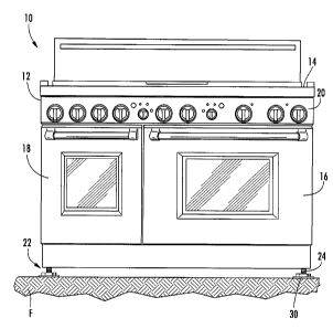
[0022] Figure 1 is a front view of a home appliance with a support assembly
according to
the preferred embodiment of the present invention;
Figure 2 is a perspective view of a threaded support leg as illustrated in
Figure 1;
Figure 3 is a perspective view of the support shoe illustrated in Figure 1;
Figure 4 is a top plan view of the support shoe illustrated in Figure 3;
Figure 5 is an exploded view of the support assembly illustrated in Figure 1;
and
Figure 6 is a perspective view of the support assembly illustrated in Figure
1.
CA 02778621 2012-05-30
Attorney Docket No.: 2012P01623US
Description of the Preferred Embodiment
[0023] Turning now to the drawings and, more particularly to Figure 1, a home
appliance
in the nature of a range is illustrated generally at 10 includes a generally
box-like, floor standing
range body 12 with a cooktop 14 mounted to the upper portion of the range body
12. The central
portion of the range body 12 defines an oven and a combination steamer and
convection oven
(not shown). The oven and combination steamer/convection oven are covered by
doors
illustrated at 16 and 18 respectively. A control panel 20 is located
intermediate the cooktop 14
and the doors 16, 18. The range body 12 is supported on a support surface such
as a floor F by
the present support assembly 22. It should be noted that the support assembly
22 is shown in
Figure 1 with a somewhat exaggerated size for clarity. The support assembly 22
includes two
primary components. These include a generally cylindrical, threaded support
leg 24 and a shoe
30 fitted to the support leg 24.
[0024] Turning now to Figure 2, the support leg 24 is a threaded cylinder 26
having a
hexagonal head 28 attached to a distal end of the support leg 24. The support
leg 24 is
threadedly received in a threaded aperture on the frame (not shown) underlying
the range
body 12 in a known manner. Rotation of the support leg 24 causes the leg to
move toward and
away from the range, thereby providing height adjustment.
[0025] As seen in Figure 3, a shoe 30 includes a generally square base 32 with
smoothly
rounded corners. A hexagonal wall 34 projects away from the base 32 and
defines a hexagonal
cavity 36 within the perimeter of the wall 34. Internally threaded cylinders
38 are formed
integrally the wall 34 along two sides of the wall 34 in opposition to one
another. The internally
threaded cylinders 38 define threaded cavities 40 for receipt of screws. The
wall 34 defines a rim
42 along an outer edge thereof.
[0026] Figure 4 illustrates the shoe 30 from above and fully reveals the
generally square
base 32 with rounded corners and the orientation of the wall 34 with the
internally threaded
CA 02778621 2012-05-30
Attorney Docket No.: 2012P01623US
6
cylinders 38 generally aligned with two of the corners of the base 32. The
shoe 30 is configured
to provide at least 1 in2 of contact for each fifty (50) pounds of appliance
weight. For example,
an approximately five hundred (500) pound appliance would distribute about one
hundred twenty
five (125) pounds per support leg assembly, presuming even weight distribution
and a support
assembly at each of four corners of the range body 12. The area of the contact
surface of the
shoe 30 would therefore be about 21/2 in2.
[0027] Turning now to Figure 5, the general relationship between the support
leg 24 and
the shoe 30 is illustrated with respect to the support assembly 22. The
receiving cavity 36 in the
shoe 30 is hexagonally shaped in a complimentary manner to the head 28 of the
support leg 24
and is configured to receive and snugly support the head 28 of the support leg
24. The support
leg 24 can be a standard bolt which, preferably, is a 5/8 ¨ 11, 5" (inch)
bolt.
[0028] A generally diamond-shaped planar collar 44 is also included in the
support
assembly 22. The collar 44 includes an opening through which the shaft 26 of
the support leg 24
may pass, resulting in the collar 44 surrounding the threaded shaft 26 of the
support leg 24. The
collar 44 is configured for retention against the rim 42 of the wall 34.
[0029] As seen in Figure 6, the support leg assembly 22 is assembled and the
support leg
24 is mounted to the shoe 30. The hexagonal head 28 is received snugly within
receiving cavity
36 of the wall 34 with the collar 44 abutting the rim 42 of the wall 34. The
collar 44 is attached
using screws 46 that are threadedly engaged with the internally threaded
cylinders 38 to firmly
retain the shoe 30 in place. The support leg assembly 22 is therefore ready
for mounting to a
range 10, as illustrated in Figure 1.
[0030] By the above, the present invention provides a height adjustable
support assembly
for a home appliance in the nature of a range that allows the use of a
conventional bolt as a leg
and provides a firmly attached foot or shoe that provides ample support for
the weight of the
CA 02778621 2012-05-30
Attorney Docket No.: 2012P01623US
7
appliance and helps distribute the weight of the appliance to prevent damage
to both the
appliance and the support surface.
[0031] It will therefore be readily understood by those persons skilled in the
art that the
present invention is susceptible of a broad utility and application. While the
present invention is
described in all currently foreseeable embodiments, there may be other,
unforeseeable
embodiments and adaptations of the present invention, as well as variations,
modifications and
equivalent arrangements, that do not depart from the substance or scope of the
present invention.
The foregoing disclosure is not intended or to be construed to limit the
present invention or
otherwise to exclude such other embodiments, adaptations, variations,
modifications and
equivalent arrangements, the present invention being limited only by the
claims appended hereto
and the equivalents thereof.