Language selection

Search

Patent 2778672 Summary

Third-party information liability

Some of the information on this Web page has been provided by external sources. The Government of Canada is not responsible for the accuracy, reliability or currency of the information supplied by external sources. Users wishing to rely upon this information should consult directly with the source of the information. Content provided by external sources is not subject to official languages, privacy and accessibility requirements.

Claims and Abstract availability

Any discrepancies in the text and image of the Claims and Abstract are due to differing posting times. Text of the Claims and Abstract are posted:

  • At the time the application is open to public inspection;
  • At the time of issue of the patent (grant).
(12) Patent: (11) CA 2778672
(54) English Title: TRANSPORTABLE SUPPORT BASE
(54) French Title: BASE DE SUPPORT TRANSPORTABLE
Status: Granted
Bibliographic Data
(51) International Patent Classification (IPC):
  • E01F 9/612 (2016.01)
  • F16M 11/00 (2006.01)
  • G09F 7/18 (2006.01)
(72) Inventors :
  • PRESCOTT, ALAIN (Canada)
(73) Owners :
  • PRESCOTT, ALAIN (Canada)
(71) Applicants :
  • PRESCOTT, ALAIN (Canada)
(74) Agent: NORTON ROSE FULBRIGHT CANADA LLP/S.E.N.C.R.L., S.R.L.
(74) Associate agent:
(45) Issued: 2018-03-20
(22) Filed Date: 2012-05-29
(41) Open to Public Inspection: 2013-11-29
Examination requested: 2016-09-09
Availability of licence: N/A
(25) Language of filing: English

Patent Cooperation Treaty (PCT): No

(30) Application Priority Data: None

Abstracts

English Abstract

A transportable support base for supporting a vertical post such as roadway sign support post in a vertical position. The transportable support base has a weighted platform having a flat bottom wall. A through slot extends from a side wall of the platform and terminates in a central region of the platform. At least a flat bottom wall has a high coefficient of friction for frictional adherence to a surface for resisting to lateral and uplifting forces applied thereto. A handle hole is disposed adjacent two opposed sides of the weighted platform and accessible from above or thereunder for manipulating the support base.


French Abstract

Une base de support transportable pour supporter un poteau vertical, comme celui dun panneau de signalisation, dans une position verticale. Ladite base comprend une plateforme lestée comportant une paroi inférieure plane. Une fente traversante sétend depuis une paroi latérale de la plateforme et se termine dans une zone centrale de cette dernière. Au moins une paroi inférieure présente un coefficient de frottement élevé pour une adhérence par frottement à une surface afin de résister à des forces latérales et ascendantes appliquées sur celle-ci. Un orifice à poignée est disposé de manière adjacente à deux côtés opposés de la plateforme lestée et est accessible par le dessus ou le dessous pour manipuler la base de support.

Claims

Note: Claims are shown in the official language in which they were submitted.

-5-

CLAIMS,
1. A transportable support base, comprising: a weighted platform having a
bottom
wall and an opposite top wall, the platform having a plurality of
interconnected side walls
including opposed parallel longitudinal walls and opposed parallel transverse
end walls, the
platform having a through slot extending from the top wall through the bottom
wall and inwardly
from one of the side walls of the platform and terminating in a central region
of the platform, at
least the bottom wall configured to frictionally adhere to a surface for
resisting to forces applied
thereto, and at least one handle hole disposed adjacent one of the
longitudinal walls for
manipulating and transporting the support base, the longitudinal walls having
a length greater
than a length of the transverse end walls.
2. The support base as claimed in claim 1, wherein the weighted platform is

constructed of a rubber material.
3. The support base as claimed in claim 1 or 2, wherein the weighted
platform is a
rectangular platform, the through slot extending from one of the end walls mid-
length to the
other end wall and disposed parallel to the longitudinal walls.
4. The support base as claimed in any one of claims 1 to 3, wherein the
through
slot has opposed parallel inner side walls and a concave end wall.
5. The support base as claimed in claim 3 or 4, wherein the at least one
handle
hole includes a first handle hole and a second handle hole, the first handle
hole being disposed
adjacent to one of the longitudinal walls, and the second handle hole being
disposed adjacent to
the other end wall.
6. The support base as claimed in claim 5, wherein the at least one handle
hole
includes a third handle hole disposed adjacent to the other longitudinal wall.
7. The support base as claimed in claim 5 or 6, wherein the second handle
hole is
disposed in a mid-length region between the longitudinal walls.
8. The support base as claimed in claims 6 or 7, wherein at least one of
the first
and third handle holes is disposed in a mid-length region between the end
walls.

-6-

9. The support base as claimed in any one of claims 1 to 8, wherein the
platform
has an undercut cavity extending inwardly from one of the side walls to the at
least one handle
hole to permit a user to introduce fingers therein to grasp said handle hole
from thereunder to lift
the support base.
10. The support base as defined in any one of claims 6 to 8, wherein the
platform
has an undercut cavity extending inwardly from one of the longitudinal walls
to at least the first
handle hole.
11. The support base as defined in claim 10, wherein the platform has two
undercut
cavities, each undercut cavity extending inwardly from one of the longitudinal
walls to a
corresponding one of the first and third handle holes.
12. The support base as claimed in any one of claims 1 to 11, wherein the
weighted
platform has a weight of between 30 to 50 lbs.
13. The support base as claimed in claim 3, wherein the rectangular
platform has a
projecting form protruding above the top wall, and a cavity in the bottom wall
to receive the
projecting form therein when two of the support bases are stacked one on top
of another to
interconnect the stacked support base to resist lateral forces.
14. The support base as claimed in claim 13, wherein the projecting form
has a flat
top surface extending parallel to the bottom wall, the cavity having a depth
which is greater than
the thickness of the projecting form.
15. The support base as claimed in any one of claims 1 to 14 in combination
with a
sign support post assembly, the sign support post assembly having a post
mounted at a lower
end on a flat transverse foot plate, and a sign securable to the post spaced
above the foot plate,
the post having at least a bottom portion thereof dimensioned to be received
in the through slot
from an open end thereof at the side wall of the platform with the foot plate
disposed under the
bottom wall.
16. The support base as claimed in any one of claims 1 to 15, wherein the
support
base is for supporting a post upright, the post having a flat transverse foot
plate at a lower end
thereof and an element secured thereto subjected to forces, the support base
resisting to lateral
and uplifting forces transferred thereto through the post.

-7-

17. The support base as claimed in any one of claims 1 to 16, wherein the
at least
one handle hole is disposed in a mid-length region of two opposed side walls
of the weighted
platform.
18. The support base as claimed in any one of claims 1 to 8, wherein the at
least one
handle hole has a cavity extending therethrough to permit a user to introduce
fingers into the at
least one handle hole from the top wall of the platform to grasp the platform.

Description

Note: Descriptions are shown in the official language in which they were submitted.


CA 02778672 2016-09-09
- 1 -
TRANSPORTABLE SUPPORT BASE
TECHNICAL FIELD
The present invention relates to a transportable support base of the type
typically utilized in road construction for supporting vertical posts to which
are secured
road signs or other members associated with road security such as barriers,
rails, etc.
BACKGROUND ART
A problem that exists with transportable support bases of the above type is
that these bases are usually constructed as rectangular bases with a slot
extending
longitudinally therein and terminating substantially at the center of the
support base.
There is provided a through hole which constitutes a handle. In order to
transport these
weighted platforms which can weigh between 30 and 50 lbs, a worker person must
grasp
the platform from above the handle hole and hinge the platform outwardly with
the arm
triceps displaced 90 , or substantially parallel to the ground, to lift it,
thus applying the
weight of the platform to the triceps arm muscle and the elbow region. During
a day, a
worker can lift several of these support bases whereby to move them or to
remove them
from a construction site. Such manipulation causes muscle, bone and even back
injury.
Another disadvantage of these transportable support bases is that they are
usually improperly stacked particularly during transport where the stack may
be subjected
to all sorts of disturbances as a transport vehicle travels over rough terrain
and they are
usually strewn all over the surface area of the box of the vehicle carrying
these support
bases. Still further, when these support bases are stacked one on top of the
other, a user
person can only grab the handle of the uppermost support base of the stack as
the handle
holes of the bases under the top one are not accessible.
SUMMARY OF INVENTION
It is a feature of the present invention to provide a transportable support
base.
Another feature of the present invention is to provide a transportable
support base wherein, in one embodiment, handle holes are provided on opposed
longitudinal sides of the support base to make it easy to lift with one or two
arms without
having to raise the arm high whereby the load is better distributed along the
arm and
wherein these bases can be carried with the arms extending downwards.
Another feature of the present invention is to provide, in one embodiment, a
transportable support base wherein several bases may be stacked one on top of
the other

CA 02778672 2016-09-09
- 2 -
and resist to transverse forces during transportation in a vehicle to prevent
disconnection
of the stack of support bases during transportation.
Another feature of the present invention is to provide, in one embodiment, a
support base having handle holes which may be grasped from under the hole when
the
bases are stacked one on top of the other whereby two or more of the bases can
be lifted
at the same time by engaging handle holes of support bases under the top
support base of
a stack.
Another feature of the present invention is to provide a transportable
support base for supporting road signs secured to upright posts provided with
foot plates.
According to the above features, from a broad aspect, the present invention
provides a transportable support base, comprising: a weighted platform having
a bottom
wall, the platform having a plurality of interconnected side walls and a
through slot
extending inwardly from one of the side walls of the platform and terminating
in a central
region of the platform, at least the bottom wall having a high coefficient of
friction for
frictional adherence to a surface for resisting to forces applied thereto, and
at least one
handle hole disposed adjacent a corresponding one of the side walls of the
weighted
platform for manipulating and transporting the support base.
BRIEF DESCRIPTION OF DRAWINGS
A preferred embodiment of the present invention will now be described with
reference to the accompanying drawings in which:
FIG. 1 is a perspective view showing the support base of the
present
invention disposed over the foot plate of a vertical post supporting a roadway
sign;
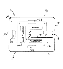
FIG. 2 is a top view of the transportable support base of the
present
invention;
FIG. 3 is an end view of Figure 2;
FIG. 4 is a side view of Figure 1; and
FIG. 5 is a side view showing a stack of transportable support
bases
illustrating the undercut cavity extending to the handle holes.

CA 2778672 2017-03-02
- 3 -
DESCRIPTION OF PREFERRED EMBODIMENTS
Referring now to the drawings and more particularly to Figure 1, there is
shown generally at 10, in phantom lines, the transportable support base of the
present
invention for supporting a road sign 11 which is connected to a vertical
support post 12
provided with a transverse foot plate 13 at a lower end thereof. The
transportable
support base 10 is disposed over the foot plate whereby to anchor it on a
support
surface 14 such as road pavement or any other support surface.
Referring now to Figures 2 to 4, there is shown the construction of the
support base 10 of the present invention. As hereinshown, the support base is
comprised of a weighted platform 15 constructed of rubber material, or other
suitable
material, and may weigh between 30 and 50 lbs. The platform is shaped as a
rectangular platform having opposed longitudinal side walls 16 and opposed
parallel
transverse end walls 17 and 17. A through slot 18 extends mid-length of one of
the end
walls, here end wall 17' and disposed parallel to the opposed side walls 16.
The through
slot 18 defines opposed parallel side walls 19 and 19' and a concavely shaped
end wall
20. The end wall 20 is disposed substantially at the center of the
transportable support
base 10. Typically these support bases have a length of about 28 inches and a
width of
inches with the through slot having a length of about 121/2 inches and a width
of
20 approximately 3% inches.
The flat bottom wall 21 has a high co-efficient of friction for frictional
adherence to a surface, such as the pavement surface 14 illustrated in Figure
1,
whereby to resist the lateral or uplifting forces applied thereto. These
forces are usually
transferred from road signs which are subjected to wind and transmitted to the
bottom
plate of the sign disposed under the support base, as shown in Figure 1. A
handle hole
22 is disposed adjacent two opposed sides, herein the longitudinal side walls
16 of the
support base and provided for manipulating and transporting the support base
by a
person inserting his fingers and/or hand through the opposed handle holes 22
whereby
to lift the support base upright. In a particular embodiment, the handle hole
22 is
disposed along the side wall 16.
As hereinshown there is optionally provided a third handle hole 23
adjacent the end wall 17 in a mid-length region thereof. The handle holes 22
are also
disposed at substantially mid-length of the two opposed longitudinal side
walls 16 for
weight distribution. In a particular embodiment, a cavity is defined in an
inner side
surface of the handle hole 22, 23 to facilitate a user to grasp the support
base 10 from
the top wall via the handle hole 22, 23.

CA 2778672 2017-03-02
- 3A -
As shown in Figures 3 and 4, the handle holes 22 and 23 are all provided with
an
undercut cavity 22' for the handle holes 22 and 23 for the handle hole 23.
These
40 undercut permits a user person to introduce his fingers therein to grasp
the

CA 02778672 2012-05-29
- 4 -
handle hole from thereunder to lift the sign support base. This is
particularly useful, as
shown in Figure 5, when support bases are stacked one on top of the other.
Otherwise,
only the top support base 10' may be lifted and the hand has to be introduced
from the
top wall 25 of the top support base 10' for grasping one support base at a
time. This
undercut 22' makes it possible for a worker person to lift two or more of the
support
bases stacked one on top of the other at the same time.
Referring again to Figures 1 to 4, it can be seen that the flat top wall 25
of the platform 10 has a projecting form 26 or plateau protruding above the
top wall and
recessed from the outer periphery of the support base. A cavity 27 (see Figure
4) is
also provided in the flat bottom wall 21 to receive the projecting form 26
therein in close
fit when two of these support bases are stacked one on top of the other to
interconnect
several stacked support bases to resist to lateral forces whereby to prevent
the bases
from falling off the stack. The projecting form 26 has a flat top surface 26'
which
extends parallel to the flat bottom wall 21. The cavity 27 has a depth which
is greater
than the thickness of the projecting form 26.
Although Figure 1 illustrates the support base as used for supporting a
road sign, it may be used for supporting any post which is provided with a
flat
transverse foot plate or flat arm(s) at a lower end thereof such as to form
barriers or a
multitude of other temporary structures. The support post 12 has at least a
bottom
portion thereof dimensioned to be received in the through slot 18 of the
support base.
It is within the ambit of the present invention to cover any other obvious
modifications of the preferred embodiment as described herein, provided such
modifications fall within the scope of the appended claims.

Representative Drawing
A single figure which represents the drawing illustrating the invention.
Administrative Status

For a clearer understanding of the status of the application/patent presented on this page, the site Disclaimer , as well as the definitions for Patent , Administrative Status , Maintenance Fee  and Payment History  should be consulted.

Administrative Status

Title Date
Forecasted Issue Date 2018-03-20
(22) Filed 2012-05-29
(41) Open to Public Inspection 2013-11-29
Examination Requested 2016-09-09
(45) Issued 2018-03-20

Abandonment History

There is no abandonment history.

Maintenance Fee

Last Payment of $347.00 was received on 2024-04-25


 Upcoming maintenance fee amounts

Description Date Amount
Next Payment if standard fee 2025-05-29 $347.00
Next Payment if small entity fee 2025-05-29 $125.00

Note : If the full payment has not been received on or before the date indicated, a further fee may be required which may be one of the following

  • the reinstatement fee;
  • the late payment fee; or
  • additional fee to reverse deemed expiry.

Patent fees are adjusted on the 1st of January every year. The amounts above are the current amounts if received by December 31 of the current year.
Please refer to the CIPO Patent Fees web page to see all current fee amounts.

Payment History

Fee Type Anniversary Year Due Date Amount Paid Paid Date
Application Fee $400.00 2012-05-29
Maintenance Fee - Application - New Act 2 2014-05-29 $100.00 2014-05-27
Maintenance Fee - Application - New Act 3 2015-05-29 $100.00 2015-05-13
Maintenance Fee - Application - New Act 4 2016-05-30 $100.00 2016-05-20
Advance an application for a patent out of its routine order $500.00 2016-09-09
Request for Examination $800.00 2016-09-09
Maintenance Fee - Application - New Act 5 2017-05-29 $200.00 2017-05-03
Final Fee $300.00 2018-02-01
Maintenance Fee - Patent - New Act 6 2018-05-29 $200.00 2018-05-01
Maintenance Fee - Patent - New Act 7 2019-05-29 $200.00 2019-05-01
Maintenance Fee - Patent - New Act 8 2020-05-29 $200.00 2020-04-20
Maintenance Fee - Patent - New Act 9 2021-05-31 $204.00 2021-03-18
Maintenance Fee - Patent - New Act 10 2022-05-30 $254.49 2022-03-21
Maintenance Fee - Patent - New Act 11 2023-05-29 $263.14 2023-03-29
Maintenance Fee - Patent - New Act 12 2024-05-29 $347.00 2024-04-25
Owners on Record

Note: Records showing the ownership history in alphabetical order.

Current Owners on Record
PRESCOTT, ALAIN
Past Owners on Record
None
Past Owners that do not appear in the "Owners on Record" listing will appear in other documentation within the application.
Documents

To view selected files, please enter reCAPTCHA code :


To view images, click a link in the Document Description column. To download the documents, select one or more checkboxes in the first column and then click the "Download Selected in PDF format (Zip Archive)" or the "Download Selected as Single PDF" button.

List of published and non-published patent-specific documents on the CPD .

If you have any difficulty accessing content, you can call the Client Service Centre at 1-866-997-1936 or send them an e-mail at CIPO Client Service Centre.


Document
Description 
Date
(yyyy-mm-dd) 
Number of pages   Size of Image (KB) 
Abstract 2012-05-29 1 14
Claims 2012-05-29 2 72
Drawings 2012-05-29 2 29
Description 2012-05-29 4 198
Representative Drawing 2013-12-09 1 9
Cover Page 2013-12-09 2 39
Description 2016-09-09 4 185
Claims 2016-09-09 3 93
Description 2016-11-14 5 192
Claims 2016-11-14 3 98
Amendment 2017-06-08 7 269
Claims 2017-06-08 3 97
Examiner Requisition 2017-07-04 4 250
Amendment 2017-08-29 4 235
Final Fee 2018-02-01 2 68
Representative Drawing 2018-02-19 1 6
Cover Page 2018-02-19 1 33
Assignment 2012-05-29 3 116
Examiner Requisition 2016-09-28 3 200
Special Order 2016-09-09 10 416
Correspondence 2016-09-20 1 23
Amendment 2016-11-14 12 437
Examiner Requisition 2016-12-05 3 214
Amendment 2017-03-02 11 429
Claims 2017-03-02 3 101
Description 2017-03-02 5 197
Examiner Requisition 2017-04-03 4 226