Note: Descriptions are shown in the official language in which they were submitted.
CA 02778799 2012-04-24
WO 2011/053500 PCT/US2010/053478
-1-
BALLOON CATHETER WITH DETACHABLE HUB,
AND METHODS FOR SAME
CROSS-REFERENCE TO RELATED APPLICATIONS
[0001] This application claims priority to U.S. Provisional Application
Ser. Nos. 61/256,773 and 61/256,755, both filed October 30, 2009, and
61/329,243, filed April 29, 2010, each of which is incorporated herein by
reference in its entirety.
TECHNICAL FIELD
[0002] Embodiments of the claimed invention relate to a medical
balloon catheter device configured for passage through an ultra-slim
endoscope. More particularly, embodiments of the claimed invention
relate to a balloon catheter including a proximal actuatable catheter lumen
seal and a detachable hub, and methods of use.
BACKGROUND
[0003] Intraductal endoscopes have an increasingly important role in
the diagnosis and nonsurgical treatment of biliary and pancreatic diseases.
Early attempts to inspect the biliary and pancreatic ducts endoscopically
have been hampered by technical limitations of the scopes. More recently,
the development of fine-caliber flexible scopes known as fiber optic
miniscopes has obviated many of these problems and has provided a
valuable new tool for a growing number of indications. These miniature
endoscopes can be used intraoperatively, during endoscopic retrograde
cholangiopancreatography (ERCP, commonly performed peroral), and
percutaneous transhepatic cholangiography (PTC).
[0004] Peroral cholangioscopy is usually performed by two
experienced endoscopists using a "mother-baby" scope system, in which a
thin fiberscope is inserted into the working channel of a large therapeutic
endoscope (e.g., a duodenoscope). Smaller and more durable miniscopes
allow for an accessory channel of their own. This accessory channel of the
CA 02778799 2012-04-24
WO 2011/053500 PCT/US2010/053478
-2-
miniscopes permits sampling for histological and cytological examination
and the insertion of catheters for dye or probes for laser or lithotripsy.
Miniscopes such as cholangioscopes can also be used for
pancreatoscopy.
[0005] The mother-baby scope technique can be expensive with
regard to personnel and equipment: two endoscopists plus assistants, two
image processors (one for each camera), expensive fiber optics in the
baby scope that can often be damaged during standard manipulation with
resulting image degradation, etc. The standard 1.2 mm working channel of
fiber optic baby scopes limits diagnostic and therapeutic options. It is
therefore desirable to provide an endoscope configured to function as a
cholangioscope by being dimensioned to be navigable through hepatic and
pancreatic ducts. Such scopes are currently available, but they encounter
problems of efficient introduction to a patient's biliary duct in a procedure
that provides high quality images (e.g., superior to fiber optics imaging) at
a desirable procedure cost. These problems include the difficulty (or
impossibility) of navigating a larger fiber optic baby scope having a greater
than 1.2 mm working channel through a mother scope (e.g.,
duodenoscope), out its side-facing distal accessory channel end past and
manipulated by the elevator, and then into a patient's biliary duct. If one is
to introduce a small scope (along the size of a "baby scope" or smaller)
into the biliary ducts or other patient body structure without a primary
(e.g.,
"mother") scope, it is necessary to provide some type of "navigating track"
because the smaller scopes are not sufficiently rigid/ robust to be directed/
navigated independently and directly through the esophagus, stomach,
and duodenum to, for example, the common biliary duct.
[0006] Accordingly, techniques are being developed to conduct
direct peroral cholangioscopy (POC). Direct POC requires only a single
endoscopist working with a single image processor, using a CMOS or CCD
(rather than - and with image quality superior to - fiber optic) camera
system that provides a 2 mm (rather than 1.2 mm) accessory channel and
CA 02778799 2012-04-24
WO 2011/053500 PCT/US2010/053478
-3-
that can be used with existing scopes, image processors, and monitors.
One example of such improved technology is disclosed in "Overtube-
balloon-assisted direct peroral cholangioscopy by using an ultra-slim upper
endoscope" (Choi, et al.; Gastrointestinal Endoscopy, 69(4):935-40; April
2009), where an over-tube with a balloon of the type used for double-
balloon enteroscopy was directed into the duodenum adjacent the Ampulla
of Vater with an ultra-slim scope supported in the lumen of the over-tube,
whereafter the scope was directed into the previously-dilated bile duct.
[0007] It would be advantageous to provide materials for efficient
introduction of an ultra-slim scope suitable for cholangioscopy and
pancreatoscopy in conjunction with use of a standard-sized endoscope
(e.g., duodenoscope) that can be exchanged out without significant loss of
procedural efficiency, but without limiting the equipment and/or procedure
to a mother-baby scope configuration, and also providing for easier, more
efficient navigation into the bile duct or other locations.
BRIEF SUMMARY
[0008] In certain embodiments, aspects of the present invention may
include a balloon catheter device including a removable hub and
configured to function as an anchored guide for an endoscopic surgical
device such as an endoscope or other endoscopic surgical device.
BRIEF DESCRIPTION OF THE DRAWINGS
[0009] FIGS. 1A-1 H show a cholangioscopy and biopsy procedure
including a scope exchange using an anchoring balloon catheter with a
removable hub;
[0010] FIG. 2 is an example of a catheter hub;
[0011] FIG. 3 is another example of a catheter hub, embodied as a
manifold;
[0012] FIG. 4A shows a balloon catheter embodiment;
CA 02778799 2012-04-24
WO 2011/053500 PCT/US2010/053478
-4-
[0013] FIGS. 4B-4D show detail views of portions of the balloon
catheter embodiment of FIG. 4A;
[0014] FIGS. 4E and 4F show the balloon catheter of FIG. 4A with
the proximal catheter-sealing valve actuated, and a detail of one valve
embodiment, respectively;
[0015] FIG. 4G shows a step of removing the manifold from the
catheter body of the balloon catheter embodiment of FIG. 4A;
[0016] FIGS. 5A-5C show another balloon catheter embodiment with
a catheter-sealing valve and removable hub;
[0017] FIGS. 6A-6C show longitudinal section and exterior views of
another balloon catheter embodiment with a side-aperture valve;
[0018] FIG. 6D shows an alternative embodiment of the balloon
catheter of FIGS. 6A-6C;
[0019] FIGS. 7A-7D show an embodiment of a balloon catheter
including a grooved piston valve embodiment;
[0020] FIGS. 7E and 7F show two embodiments for connecting the
housing to the catheter body of the embodiment shown in FIGS. 7A-7D;
[0021] FIG. 8 shows another balloon catheter embodiment, with an
elongate wire valve;
[0022] FIGS. 9-9D show another balloon catheter embodiment, with
a distal flap-type valve;
[0023] FIG. 10 shows another embodiment of a catheter device with
a removable manifold; and
[0024] FIGS. 1OA-10B show a partial longitudinal section view of the
device 1000 of FIG. 10.
DETAILED DESCRIPTION
[0025] DEFINITIONS
[0026] Ultra-slim endoscopes, as that term is used herein, refer to
endoscopes having an outer diameter of about 6.0 mm or less (including
less than 5.0 mm). The term "hub" refers to the proximal end structure of a
CA 02778799 2012-04-24
WO 2011/053500 PCT/US2010/053478
-5-
balloon catheter including a connection structure (e.g., Luer-type or other
fluid-patent connection) configured for effective connection to provide a
path of fluid communication between a source of inflation fluid, a catheter
inflation lumen, and a balloon lumen, and includes manifold-style hubs that
may have more complex or ancillary structures. The terms "distal" and
"proximal" are to be understood with their standard usages, referring to the
direction away from and the direction toward the handle/ user end of a tool
or device, respectively (i.e., away from and toward the patient,
respectively).
[0027] A cholangioscopy procedure using a scope-exchange
facilitated by a balloon catheter including a proximal actuatable sealing
valve and removable hub is described with reference to FIGS. 1A-1 H.
Embodiments of different catheters including a proximal actuatable
catheter-sealing valve and removable hub are described thereafter.
[0028] FIG. 1A shows a side-viewing endoscope embodied as a
duodenoscope 152 that has been directed into the duodenum 150 of a
patient adjacent the Ampulla of Vater about the Sphincter of Oddi 154,
which is shown as having been cannulated (e.g., through a
sphincterotomy). A loop-tipped catheter 100 extending through a working
channel of the duodenoscope 152 is shown being directed through the
cannulated sphincter 154 into the common bile duct 156.
[0029] FIG. 1 B shows an alternative method for introducing the loop-
tipped catheter 100 through the cannulated sphincter 154 into the common
bile duct 156 using a wire guide 158. In this embodiment, the wire
guide 158 is first navigated into the common bile duct 156. Then, the
loop 102 of the catheter 100 is looped around the wire guide 158 and
directed in monorail fashion therealong into the common bile duct 156.
[0030] Regardless of which method is used to direct the catheter 100
into the common bile duct 156, the catheter 100 may be directed further
into the hepatic branch side (or pancreatic duct side) of the common bile
duct 156. Then, as shown in FIG. 1C, the balloon 104, which preferably
CA 02778799 2012-04-24
WO 2011/053500 PCT/US2010/053478
-6-
will be a compliant balloon, may be inflated (e.g., as shown in the hepatic
duct 157, although it may be anchored in the common bile duct 156 or a
different branch, including in the pancreatic duct as those of skill in the
art
will appreciate that pancreatoscopy may also be practiced within the scope
of the present invention). It is preferable that the balloon 104 be inflated
sufficiently to anchor the catheter 100, but that it does not significantly
distend the ductal surface contacted by the inflated exterior balloon
surface. Compliant balloons may be made of latex or other biocompatible
material having desirable elasticity. In some embodiments, a balloon may
be non-compliant in accords with desirable manipulation during a surgical
procedure.
[0031] FIG. 1D shows the proximal end of the balloon catheter 100,
with a hub embodied as a manifold 110 being detached therefrom. Prior to
detachment of the manifold 110, a valve 120 is actuated to seal the
proximal end of the balloon catheter 100 to maintain inflation fluid pressure
in the balloon 104 (in the present application, an "actuated valve" is in a
closed configuration, and a "non-actuated valve" is in an open
configuration). The valve and manifold may be embodied in the manner
described with reference to FIGS. 4A-8 below, with features combined
therefrom, or with another valve/ sealing structure covered by the claims
including all equivalents. As will be appreciated with reference to FIG. 1 E,
this removal of the proximal manifold 110 allows a user to withdraw the
duodenoscope 152 over the catheter 100 while the catheter 100 remains in
place, anchored by the balloon 104 (as shown in FIG. 1 C).
[0032] Next, an ultra-slim endoscope 160 is directed distally along
the catheter 100. Specifically, the proximal catheter end is inserted into
the distal end of an accessory/working channel of the ultra-slim scope 160.
Then, as shown in FIG. 1 F, the catheter 100 may serve as a guide,
allowing the distal end of the ultra-slim scope 160 to be directed into the
common bile duct 156. Thereafter, as shown in FIG. 1G, the balloon 104
may be deflated (e.g., by allowing the inflation fluid to escape or by
CA 02778799 2012-04-24
WO 2011/053500 PCT/US2010/053478
-7-
providing negative pressure to withdraw it using a syringe or vacuum
source) and the catheter 100 withdrawn, freeing up the accessory channel
of the ultra-slim scope 160. A user may then introduce a diagnostic or
therapeutic instrument through the accessory channel of the ultra-slim
scope 160 such as, for example, biopsy forceps 162 as shown in FIG. 1 H.
[0033] FIG. 2 shows a conventional basic catheter hub 210 for a
catheter 200. The hub 210 includes a Luer-type connector 212 and
wings 213 configured to facilitate manipulation. FIG. 3 shows a
conventional catheter hub configured as a manifold 310. The manifold 310
includes a Luer-type connector 312 on a side branch 318 and another
connector 316 on a linear branch 314 that is substantially coaxial with the
longitudinal axis of the catheter 300. The manifold 310 includes a main
lumen 306 that is in fluid communication with a lumen 308 of the side
branch 318. Such conventional hubs, including manifolds, are fixedly and
irremovably attached to the catheter body. It will be appreciated that the
outer diameter and/or cross-sectional area of these and other conventional
hubs are such that they would not fit through an elongate surgical device
such as, for example, a lumen of a large-bore catheter, polymer biliary
stent, working/ accessory channel of an endoscope or other minimally-
invasive image-capture device.
[0034] Embodiments of the presently-disclosed device and method
include a hub that is removable from a catheter body, including a sealing
structure such as a valve that is configured to maintain inflation fluid/
pressure in a balloon sufficient to keep that balloon and catheter anchored
in a duct of a patient body while an elongate surgical device is passed over
a proximal end of the catheter (with the hub removed). Alternatively, or in
addition, a hub may be reattached to aid in deflating the balloon. Valve
embodiments of the present invention preferably provide a transverse
cross-sectional area that is less than or at least not substantially greater
than the transverse cross-sectional area of the catheter. With this
configuration, an elongate surgical device (e.g., duodenoscope, ultra-slim
CA 02778799 2012-04-24
WO 2011/053500 PCT/US2010/053478
-8-
endoscope, other camera or image-capturing device, polymer stent, larger-
bore catheter, etc.) may be passed over the entire length of a catheter
device (including the valve) of the present invention when the balloon is
deflated, and/or the entire length of the catheter device may be passed
through a central lumen, working channel, or other opening of the elongate
surgical device. In other words, the outer diameter of the valve and of the
balloon when deflated most preferably is not significantly greater than the
outer diameter of the elongate catheter body, such that the entire device
(with the hub removed) may be passed through the lumen of an elongate
surgical device.
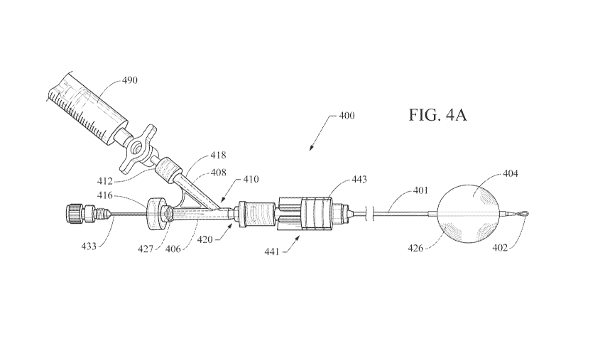
[0035] FIGS. 4A-4D show, respectively, a balloon catheter 400 with
a removable hub embodied as a manifold 410 (FIG. 4A) and detail
illustrations of a seal-actuation stylet 433, plug-style valve 420, and a
longitudinal section view of the distal catheter end with balloon 404 and
loop-tip 402. As shown in FIG. 4A, the manifold 410 includes an inflation
syringe 490 attached to its side branch 418 at a connector end 412. A
branch lumen 408 provides a path of fluid communication from the
syringe 490 to the main lumen 406, which is in fluid communication with
the inflation lumen 424 of the elongate catheter body 401 and, thereby, the
balloon inflation lumen 426. A proximal portion of the main manifold
lumen 406 includes a Tuohy-Borst seal 427 that provides for passage
therethrough of the seal-actuation stylet 433 without significant loss of
inflation fluid pressure from the inflation lumens 424, 426. The phrase
"Tuohy-Borst seal" is intended to include the specific structure associated
in the art with that name, as well as all equivalent simple seals configured
for maintaining fluid-patency during introduction of a solid item through a
seal.
[0036] The manifold 410 is attached to the elongate body 401 of the
catheter 400 by a fluid-tight compression seal 441 including a sliding
member 443 that enforces a compression fit when in the distal position
shown, and that releases the catheter body when retracted proximally.
CA 02778799 2012-04-24
WO 2011/053500 PCT/US2010/053478
-9-
Other connectors suitable for fluid-tight but detachable connection of a
manifold to a catheter body (e.g., threaded, bayonet-connector,
gasket/friction-fit) are known or may be developed in the future and
practiced within the scope of the present invention. The balloon 404 is
shown as inflated.
[0037] The seal-actuation stylet 433 is shown in the detail view of
FIG. 4B. It includes a metal or other generally rigid distal body 434 and a
proximal structure 435 configured for engaging/disengaging the seal-
actuation stylet 433 with the proximal main body connector 416 of the
manifold and for longitudinal manipulation of the body 434 within the main
manifold lumen 406.
[0038] A proximal end of the catheter body 401 (generally obscured
by the manifold 410 in FIG. 4A) is shown in the detail view of FIG. 4C. The
catheter 400 includes a stiffening wire 431 embedded in its wall some
distance distal of the absolute proximal catheter end. A cannula 432
bridges the "wired" and "non-wired" catheter region. A simple valve 420
includes the proximal end of the catheter 400 and a plug 440. The
plug 440 is shown as slightly proximal of the absolute proximal catheter
end, such that the valve 420 is in an open/ non-actuated state that will
allow free passage of an inflation fluid through the catheter inflation
lumen 424.
[0039] FIG. 4D shows a partial longitudinal section view of the distal
portion of the catheter assembly of FIG. 4A. The balloon 404 is shown
around the distal body portion of the catheter 400. A generally helical
metal coil 445 may be disposed in the catheter in this distal portion to
provide structural strength for navigating the catheter 400 and to reinforce
the catheter body in a region where one or more apertures (not shown) are
included to provide a path of fluid communication from the catheter
lumen 424 into the balloon lumen. The loop-tip 402 is attached to the
stiffening wire 431, and - in the illustrated embodiment - is sealed with the
catheter 400 by a generally frustoconical adhesive or polymer structure
CA 02778799 2012-04-24
WO 2011/053500 PCT/US2010/053478
-10-
that also seals the distal end of the catheter inflation lumen. The loop-
tip 402 preferably provides a generally atraumatic distal end that will
facilitate navigation through body lumens and also permit monorail-style
navigation along a wire guide as described above with reference to
FIG. 1B.
[0040] Actuation of the valve 420 and removal of the manifold 410
from the catheter 400 are described with reference to FIGS. 4E-4G.
FIGS. 4E and 4G show a user having advanced the seal-actuation
stylet 423 distally against the plug 440. FIG. 4F shows that this action
actuates the valve 420 by engaging the plug 440 into the proximal end of
the catheter inflation lumen 424, which will maintain the pressure needed
to keep the balloon 404 inflated as shown in FIG. 4E by occupying and
substantially sealing the catheter inflation lumen 424. FIG. 4G shows the
manifold 410 with the compression seal 441 having been disengaged by
retracting the sliding member 443 proximally. This disengagement
releases the sealed proximal end of the catheter body 401, allowing an
elongate surgical device (e.g., duodenoscope, ultra-slim endoscope,
polymer stent, larger-bore catheter) to be moved over that end during or
after a scope exchange or similar scope manipulation as is described
above with reference to FIGS. 1A-1 H. The plug 440 may be manually
removed from the proximal catheter end to allow deflation of the
balloon 404.
[0041] FIGS. 5A-5C show a partial longitudinal section view of
another embodiment of a balloon catheter 500 including an elongate
catheter body 501, a removable hub 510, and a method of use thereof.
FIG. 5A shows the catheter 500 with a balloon 504 in a deflated state. The
proximal hub 510 is shown as a very basic hub, but may alternatively be
embodied as a hub like the ones shown in FIGS. 2-3 or other hubs
(including manifolds) now known or later developed. An actuatable valve
is embodied as a pliable seal 520 configured to substantially form a seal
sufficient to retain inflation fluid in the catheter inflation lumen 524
CA 02778799 2012-04-24
WO 2011/053500 PCT/US2010/053478
-11-
when/where the seal contacts itself. The seal 520 is configured to seal
around the distal end of the hub 510 as shown in FIG. 5A. FIG. 5B shows
the balloon 504 inflated, with the hub 510 still in place through the
seal 520.
[0042] FIG. 5C shows the seal 520 in an actuated state, effected by
proximal retraction and removal of the hub 510 therefrom. Removal of the
hub 510 allows the pliable surface of the seal 520 to collapse and contact
itself in a sealing manner that will maintain sufficient inflation fluid
pressure
in the balloon lumen and catheter inflation lumen 524. The seal 520 may
be constructed of an elastic material such as latex, silicone (including a
gel-filled and/or intact-gel silicone construction), soft acrylic polymer or
any
material similar to any of these in structure and/or function, provided said
material will effect a suitable seal in the circumstances described. In
contrast to other embodiments shown herein, which may require a
separate actuation step, the valve seal 520 is self-actuating, that is it is
actuated automatically by the act of removing the hub 510. Other valve
embodiments may be modified within the scope of the present invention to
obtain the same function. This and other embodiments preferably are
configured to allow reattachment of the hub 510 in a manner that will re-
open the valve seal 520 and facilitate deflation of the balloon 504.
[0043] FIGS. 6A-6D show proximal portion views of other
embodiments of a catheter 600 with a proximal actuatable valve 620 and a
distal balloon 604. This valve 620 may be configured for use with a
removable hub or manifold 410 such as the one shown in FIGS. 4A, 4E,
and 4G and referred to by reference here, which reference will readily be
understood by those of skill in the art (e.g., by envisioning insertion of the
catheter 600 into a manifold as described). In the present embodiment,
the catheter 600 includes a side aperture 603 configured to align with the
branch lumen 408 of the manifold 410 when the manifold is attached to the
catheter body 601. In this manner, the branch lumen 408 will provide a
path of fluid communication with the catheter lumen 624.
CA 02778799 2012-04-24
WO 2011/053500 PCT/US2010/053478
-12-
[0044] In the embodiment shown in FIG. 6A, the valve 620 includes
a generally cylindrical housing 670 retained by overmolding, friction fit, or
adhesive 629 within the proximal end of the catheter lumen 624. The
housing 670 includes at least one side aperture 672 configured to at least
partially align with the catheter side aperture 603 to provide a path of fluid
communication with the catheter lumen 624. The inner diameter of the
housing 670 includes a proximal stop 676 and a distal stop 677. The
valve 620 also includes a generally columnar plunger 674 with a flared
distal end 675 disposed slidably between the proximal and distal
stops 676, 677. The flared distal end 675 may be a continuous structure
with the plunger 674, or it may be formed as an o-ring set into a groove or
other inset at or near the distal end of the plunger 674.
[0045] As shown in FIG. 6A, the plunger 674 drawn in solid-line is in
a proximal position with its flared distal end 675 disposed near or against
the proximal stop 676. This position will not significantly occlude the
housing aperture 672 or the catheter aperture 603, thereby providing a
free, patent path of fluid communication between the manifold branch
lumen 408 and the catheter lumen 624. FIG. 6A also shows a dashed-line
image of the plunger 674 in a valve-actuated configuration where the flared
distal end 675 is disposed near or against the distal stop 677, substantially
forming a seal preferably sufficient to retain inflation fluid in the balloon
604
and catheter lumen 624. Actuation of the valve 620 in conjunction with use
of a hub like the manifold 410 may be effected in the same manner as
actuating the plug 440 of FIG. 4F - by using a stylet (e.g., stylet 423) to
push the plunger 674 distally into the actuated position, thereby sealing the
catheter lumen 624 to allow removal of the hub 410 without significant loss
of inflation fluid or balloon volume. When desirable, the plunger 674 may
be retracted again to allow for deflation of the balloon 604.
[0046] FIGS. 6B-6C show an alternative embodiment of the
catheter 600 including a valve 690 without an internal housing. The
valve 690 includes at least one side aperture 603 and a plunger 692 with
CA 02778799 2012-04-24
WO 2011/053500 PCT/US2010/053478
-13-
an end portion 694 dimensioned to fully occupy a cross-sectional area of
the catheter lumen 624. The plunger 692 is shown in FIG. 6B as being
located proximal of the distal end of the aperture 603 such that inflation
fluid may freely flow through the aperture 603 into/ out of the catheter
lumen 624. The valve 690 may be actuated/closed by distal advancement
of the plunger 692 such that the plunger end portion 694 will fully occlude
the catheter lumen 624, creating a seal that will allow removal of a hub
without deflating a distal balloon attached thereto. The embodiment shown
in FIG. 6D is substantially similar to that shown in FIGS. 6B-6C, except that
its side aperture is embodied as a plurality of side apertures 603 that may
selectively be blocked or left open by the end portion 694 of the
plunger 692.
[0047] FIGS. 7A-7F show another valve embodiment 720 for a
balloon catheter 700 including an elongate catheter body 701 and a
detachable hub (not shown). The valve 720 includes an outer housing 770
with an inward-facing surface 771 that may be longitudinally-movably
secured to the catheter body 700 with, for example, a detent
connection 765 (described below with reference to FIG. 7E), a threaded
connection 775 (described below with reference to FIG. 7F), or other
connection mechanism providing for controlled longitudinal movement of
the housing relative to the catheter body 701. The catheter body 701 and
housing 770 are generally shown in longitudinal section. A grooved
piston 792 is longitudinally slidably disposed within the housing 770 and
preferably is dimensioned to contact or very nearly contact the inner
diameter of the housing. At least at its distal end, the depth of its
grooves 793 is equal to or less than a thickness of the wall of the catheter
body 701. An o-ring 794 may be disposed at the proximal end of the
piston 792 within the housing.
[0048] FIG. 7A shows a longitudinal section view of the valve 720 in
a non-actuated/ open position, with arrow-tipped lines 759 indicating the
path of fluid communication for inflation fluid through the proximal end of
CA 02778799 2012-04-24
WO 2011/053500 PCT/US2010/053478
-14-
the housing 770, along the grooves 793, and into the catheter lumen 724.
FIG. 7B shows an exterior view of the housing 770 and body 701 of the
catheter 700. FIG. 7C shows a longitudinal section view of the valve 720
in an actuated/ closed position, wherein the housing 770 is distally
advanced onto and relative to the catheter 700. Within the housing 770,
the catheter 700 generally seals the distal ends of the grooves 793 and the
o-ring 794 substantially forms a seal between the proximal ends of the
grooves 793 and a proximal inner face of the housing 770. FIG. 7D shows
an end perspective view of the valve position shown in FIG. 7C, illustrating
the relative positions of the catheter 700, grooved piston 792, and o-
ring 794 as they would appear in a closed/sealed configuration with the
housing 770 removed.
[0049] The housing 770 may be attached to the catheter 700 by
frictional contact between generally smooth surfaces as shown in FIGS. 7A
and 7C. However, it may be preferably to provide a more secure
engagement. FIG. 7E shows a detent connection 765 between the inward-
facing surface 771 of the housing 770 and the outer surface of the
catheter 700. When the valve is non-actuated (in an open/free-flow
configuration), a first circumferential detent ridge 766 on the inward-facing
surface 771 of the housing 770 will substantially sealingly engage a first
circumferential groove 767 on the catheter exterior surface. As shown in
FIG. 7E, when the valve 720 is actuated (in an closed configuration), the
first circumferential detent ridge 766 on the inward-facing surface 771 of
the housing 770 substantially sealingly engages a second circumferential
groove 768 on the catheter exterior surface. In the embodiment shown in
FIG. 7F, the inner surface of the distal housing portion includes a threaded
surface 776 that mates with a complementarily threaded exterior
surface 777 of the catheter body 701. It will readily be appreciated how
this valve embodiment may be sealed by advancingly engaging the
threaded surfaces 776, 777 to draw and seal the piston 792 and
housing 771 firmly against the catheter body 710.
CA 02778799 2012-04-24
WO 2011/053500 PCT/US2010/053478
-15-
[0050] FIG. 8 shows another embodiment of a balloon catheter 800
with a hub 810 detachably connected to a tubular body 801. The
removable proximal hub 810 is attached to the tubular body 801 in this
embodiment by a friction fitting 841. Tubular body 801 includes a
longitudinal lumen 824 extending therethrough and providing a path of fluid
communication with a distal balloon 804. The tubular body 801 includes a
distal metal coil 845 configured for providing structural support of the
distal
end including a loop tip 802, which is connected to a longitudinal stiffening
wire 831 embedded in the wall of the tubular body 801. A cannula 832
may be included to provide structural reinforcement across the end of the
core wire 840 and the portion of the tube body 801 supported only by the
coil 845 and stiffening wire 831.
[0051] A valve/seal allowing removal of the hub 810 for a scope-
exchange or other action without losing inflation pressure of the
balloon 804 is provided by an elongate flexible solid core wire 840 that
generally (but not completely) occupies a cross-sectional area of the tube
lumen 824. In preferred embodiments, the outer diameter of the tube
body 801 will be dimensioned to allow easy passage over its outer surface
of an ultra-slim endoscope. In addition, it is preferable that it include
externally and internally lubricious surfaces to allow movement of the core
wire 840 and overlying structures without damaging or significantly moving
the tube body 801 if/when it is anchored in a patient's body structure by its
balloon 804. The very close tolerance of the core wire outer diameter and
tube inner diameter will form an effective seal, minimizing or stopping loss
of inflation fluid from the balloon 804 when inflated to anchor the
device 800 during a procedure (e.g., as shown in FIGS. 1A-1 H), but
inflation can be effected using a high-pressure fluid-introduction source
configured to overcome the flow resistance of the close tolerance. The
core wire 840 may be removed from the tube lumen 824 to allow deflation
of the balloon 804.
CA 02778799 2012-04-24
WO 2011/053500 PCT/US2010/053478
-16-
[0052] In one exemplary embodiment, the tube 801 may be
constructed of PEEK with a silicone coating, having an outer diameter of
about 0.035 inches (about 0.89 mm) and an inner diameter of about
0.023 inches (about 0.58 mm), with a core wire constructed of nitinol and
having an outer diameter of about 0.021 to about 0.0215 inches (about
0.53 to about 0.55 mm), with a gold coil lip tip and platinum-gold coil-spring
base, and a female Luer hub.
[0053] A distal portion of another balloon catheter 900 with a
detachable hub (not shown) is shown in partial longitudinal section in
FIGS. 9A-9D. It includes an elongate catheter body 901 having a catheter
lumen 924 and a balloon 904. An aperture 925 provides a path for fluid
communication between the balloon lumen 905 and the catheter
lumen 924. A valve mechanism 920 includes a valve sleeve 995 disposed
around the catheter wall 901, providing a fluid-tight seal. The valve
sleeve 995 includes a valve flap 996 that is shown covering the
aperture 925 in a fluid-tight manner in FIG. 9A, where pressure from
inflation fluid in the balloon lumen 905 keeps the flap 996 sealed against
the catheter wall 901 when the balloon is inflated, but which may be
opened to allow inflation by distal pressure of inflation fluid being
introduced through the catheter lumen. The surfaces of the flap and/or
catheter wall where they contact may be treated (e.g., with tacky adhesive,
gel material, static charge, magnetic materials) to an enhanced but
disruptable fluid-tight contact therebetween. A ramp 997 occupies and
seals the distal end of the catheter lumen 924. To illustrate more clearly
the construction of the valve 920, FIG. 9B shows a transverse section view
along line 9B-9B of FIG. 9A, and FIG. 9C shows a transverse section view
along line 9C-9C of FIG. 9A (for the sake of illustrative simplicity, the
balloon 904 is not shown in FIGS. 9B-9C).
[0054] As described above with reference to the other embodiments,
this catheter 900 may function as an anchored guide or track for a camera
exchange (e.g., "exchange out" a duodenoscope, and "exchange in" an
CA 02778799 2012-04-24
WO 2011/053500 PCT/US2010/053478
-17-
ultra-slim endoscope) with the valve 920 above allowing a user to remove
the proximal hub (e.g., basic hub, manifold or other proximal structure that
normally would preclude one from advancing/ retracting a scope or other
device over the proximal catheter end) without losing significant pressure
from the balloon lumen 905, thereby allowing the balloon 904 to function
as an anchor.
[0055] As shown in FIG. 9D, when it becomes desirable to deflate
the balloon 904, a user may introduce a loop-tipped wire 998 or other
flexible elongate device through the catheter lumen 924, directing it distally
therethrough and allowing the ramp 997 to deflect it into the flap 996,
opening the flap 996 to allow deflation of the balloon 904 and removal of
the catheter 900 (e.g., in a manner similar to that shown in FIG. 1 G).
[0056] FIGS. 10, 10A, and 10B show another embodiment of a
catheter 1000 with a proximal actuatable valve including a hub/
manifold 1010. FIG. 10 shows a partially disassembled view including a T-
shaped manifold 1010, catheter body 1001, and sealing rod member 1033.
Proximal and distal cannulas 1032a, 1032b are crimped or otherwise
attached around the outside diameter of the catheter body 1001 in a
manner that reduces the inner diameter of the catheter lumen 1024 for its
length within each cannula (see FIGS. 10A-10B). The sealing rod
member 1033 includes a distal sealing ball 1034, the outer surface of
which is configured to frictionally sealingly contact the inner diameter of
the
catheter lumen 1024. The outer diameter of the distal sealing ball
preferably is at least equal to or greater than the inner diameter of the
cannulas 1032a, 1032b, such that the ball 1034 - when disposed
therebetween - cannot be moved proximally or distally past those
cannulas. The proximal portion of the rod member 1033 preferably
includes a grasping member 1035, shown here as a ball. The grasping
member 1035 most preferably has a sufficiently low profile that the
manifold 1010 can be removed proximally over it without forcing it to move
longitudinally.
CA 02778799 2012-04-24
WO 2011/053500 PCT/US2010/053478
-18-
[0057] The sealing ball 1034 is shown as being disposed at the distal
end of the rod member 1033. It should be appreciated that, in other
embodiments practicable within the scope of the present invention, the rod
member 1033 may extend distally beyond the sealing ball 1034 in a
manner that may provide support for the catheter body 1001. The outer
diameter of the body of the rod member 1033 preferably is sufficiently less
than the inner diameter of the catheter lumen 1024 to permit fluid passage
through the lumen when the rod body is present.
[0058] When assembled in the manner shown in FIGS. 10A-10B,
compression sealing members 1043 of the manifold 1010 circumferentially,
sealingly engage the catheter body 1001 and/or cannulas 1032a, 1032b
with a releasable compression fit (e.g., by threaded connection). The
manifold 1010 is configured with a central side branch 1018 that includes a
fluid-source connector end 1012 to which an inflation fluid supply (e.g.,
syringe) may be attached. The distal end (not shown) of the catheter
body 1001 may be configured with an inflation balloon and other features
such as are shown in FIG. 4A. A branch lumen 1008 of the side
branch 1018 provides a path of fluid communication to the catheter
lumen 1024 via a catheter side aperture 1024a.
[0059] FIGS. 10A-10B show a partial longitudinal section view of the
device 1000 of FIG. 10. FIG. 10A shows the device 1000 in an open,
unsealed state where inflation fluid may freely be directed through the
branch lumen 1008, catheter side aperture 1024a, and distally through the
catheter lumen 1024. FIG. 10B shows the device 1000 in an actuated,
sealed state. In FIG. 10B, the rod member 1033 is advanced so that the
sealing ball 1034 moves distally past the catheter side aperture 1024a,
creating a proximal-end seal of the catheter lumen 1024 that preferably is
sufficiently strong to maintain fluid pressure within a distal anchoring
balloon (not shown, see FIG. 4A and corresponding text). The distal
cannula 1032b prevents the ball 1034 from moving too far distally. In
preferred embodiments, a user may have a tactile sense of the ball 1034
CA 02778799 2012-04-24
WO 2011/053500 PCT/US2010/053478
-19-
moving distally past the catheter side aperture 1024a due to the tight
tolerances of the ball's outer diameter and the inner diameter of the
catheter lumen 1024.
[0060] The compression members 1043 of the manifold 1010 may
be loosened, and the manifold 1010 may be removed by drawing it
proximally over the proximal ends of the catheter body 1001 and rod
member 1033. This removal will not disrupt the seal effected by the
sealing ball 1034 with the inner diameter of the catheter lumen 1024, and
will leave only the low profile/ outer diameter of the catheter 1001 over
which a tool or device (e.g., duodenoscope, ultra-slim intraductal
endoscope, surgical device) may be advanced or withdrawn while the
distal catheter end remains anchored by a balloon in the manner described
above with reference to other embodiments.
[0061] In one illustrative embodiment, the catheter 1001 may be
configured as a flexible catheter having an inner diameter of about
0.034 inches and an outer diameter of about 0.053 inches. The sealing
ball 1034 may have an outer diameter of about 0.037 inches, such that it
tightly engages and slightly compresses and/or deforms the catheter wall,
providing a fluid-patent frictional sealing contact. The cannulas 1032a,
1032b preferably are rigid (e.g., metal) and may have an inner diameter of
about 0.034 inches, which will not permit passage of the sealing ball 1034
therethrough. The grasping member 1035 may have an outer diameter of
about 0.053 inches.
[0062] Those of skill in the art will appreciate that embodiments not
expressly illustrated herein may be practiced within the scope of the
present invention, including that features described herein for different
embodiments may be combined with each other and/or with currently-
known or future-developed technologies (including, for example, different
types of valves useful for sealing a catheter lumen while allowing passage
thereover of an endoscopic surgical device, or a removable low-profile
clamp configured to seal the catheter lumen while allowing passage
CA 02778799 2012-04-24
WO 2011/053500 PCT/US2010/053478
-20-
thereover of an elongate surgical device) while remaining within the scope
of the claims presented here. It is therefore intended that the foregoing
detailed description be regarded as illustrative rather than limiting. And, it
should be understood that the following claims, including all equivalents,
are intended to define the spirit and scope of this invention.