Note: Descriptions are shown in the official language in which they were submitted.
CA 02778870 2012-04-24
MONITORING A SUSPENSION AND TRACTION MEANS OF
AN ELEVATOR SYSTEM
The present invention relates to an elevator system, in which at least one
elevator
car, or at least one lift cage, and at least one counterweight are moved in
opposite
directions in an elevator hoistway, wherein the at-least one elevator car and
the at-least
one counterweight run along guiderails, are supported by one or more
suspension-and-
traction means, and are driven by a traction sheave of a drive unit. The
present invention
relates particularly to the one or more suspension-and-traction means, viz, to
a method of
monitoring the one or more suspension-and-traction means of the elevator
system, and to a
device according to the invention for executing this method.
In elevator systems it has proved advantageous to use suspension-and-traction
means that are composed of at least one electrically conductive steel rope and
non-
conductive sheath, or of ropes made of special plastics, in which an electric
conductor is
integrated. By this means, for the purpose of monitoring the individual
suspension rope or
ropes ¨ also known as cords ¨ a monitoring current can be applied. In the
electric circuit
so formed, or in several so-formed electric circuits, the current flow or
current strength,
the voltage, the electrical resistance, or the electric conductivity, is
measured and provides
information about the intactness and/or degree of wear of the suspension-and-
traction
means.
So, for example, the published patent application DE-A1-39 34 654 discloses a
serial connection of all of the individual cords and an ammeter, or, instead
of an ammeter,
an electronic circuit, in which the base resistance of an emitter-connected
transistor is
measured.
Patent US-B2-7,123,030 discloses a calculation of the electrical resistance
through
a measurement of the momentary voltage by means of a so-called Kelvin bridge,
and a
comparison of the voltage value determined by this means with an input
reference value.
International patent publication WO-A2-2005/094250 discloses a temperature-
dependent measurement of the electrical resistance value, or of the electrical
conductance,
in which the varying ambient temperature, and hence also the assumed
temperature of the
suspension means, is taken into account, which, particularly in tall elevator
hoistways, can
greatly vary.
1
CA 02778870 2012-04-24
A further international patent publication, WO-A2-2005/094248, discloses
special
circuits of the individual cords, to avoid electric fields and to avoid
orthogonally migrating
ions between the individual cords.
A European patent publication, EP-Al-1 275 608, of an application by the same
applicant as for the present application, discloses a monitoring of the sheath
by application
to the cords of a plus-pole of a source of direct current, so that in the case
of a damaged
sheath, a mass contact occurs.
However, disadvantageous in all of these known monitorings of the suspension-
and-traction means is that the information about the signs of wear, or about
the prevailing
anomalous state of the suspension-and-traction means, is present only as an
overall result.
In particular, cross-connections (short circuits) between cords greatly
falsify the overall
result.
An objective is therefore now to eliminate the said disadvantages of
conventional
monitoring devices, and to propose a monitoring device for suspension-and-
traction means
that delivers more accurate and qualitatively classifiable information about
its state,
thereby achieving a higher level of safety for the elevator system, and
avoiding cost-
intensive excessively early replacements of the suspension-and-traction
sheaves.
A fulfillment of the objective consists in the first place in the arrangement
of an
electric circuit that can be applied to the suspension-and-traction means and
contains at
least two electric resistors, or resistance elements, which possess different
resistance
characteristics. In the individual case, this can be the resistance value
itself, in principle,
however, also the tolerance, the maximum power loss, the temperature
coefficient, or,
taking the same into consideration, the breakdown voltage, the stability, the
(parasitic)
inductance, the (parasitic) capacity, the noise, the impulse stability, or
combinations
thereof.
A first variant of a corresponding arrangement thus foresees a suspension-and-
traction means that possesses at least one conductive cord. This suspension-
and-traction
means is largely sheathed, advantageously with an electrically insulating
material such as,
for example, rubber or a polyurethane. Connected to each of the conductive
ends of the
cord are mutually differing resistors. Additionally or alternatively, a
further resistor,
which differs again from the first two mutually differing resistors, is
arranged on a contact
point which is passed over by the suspension-and-traction means when in
operation.
2
CA 02778870 2012-04-24
This contact point can, for example, be any return pulley, whether a return
pulley
that is arranged locationally-fixed in the elevator hoistway, or the, or one
of the, return
pulley(s) of the counterweight or of the elevator car. As contact point, which
is passed
over by the suspension-and-traction means, a so-called retainer can also be
considered, i.e.
an anti-derailer, such as return pulleys usually have. Also, divertcr pulleys
of the
counterweight, or of the elevator car, and in principle also the traction
sheave, as well as
metallic hoistway components, can be considered. The contact point can be a
metallic
surface, which, for example, is coated with a highly conductive material, such
as copper or
brass. Also brush contacts, in the form of, for example, carbon fiber brushes,
copper
brushes, or similar, can be used. The use of brushes has the advantage that
the brushes
enter into close contact with a surface of the suspension-and-traction means,
i.e. that they,
for example, exactly follow a contoured, or formed, surface, so that the
entire surface is
contacted. However, of primary importance is that the contact point is
conductive, and
advantageous that it can be grounded ¨ in the case of operation of the
monitoring device
with direct current ¨ or that a voltage can be applied to the contact point ¨
in the case of
operation of the monitoring device with alternating current ¨ and that a
contact with the
conductive part, or conductive parts, of a suspension-and-traction means is
possible in
principle if this conductive part of the suspension-and-traction means comes
into contact
with this contact point.
This last-mentioned contact between the contact point, for example the return
pulley, and the conductive part or conductive parts of the suspension-and-
traction means
can arise when, for example, individual wires of the cord break, and
subsequently
penetrate through the sheath. These broken wires touch against the contact
point and thus,
during the time of their touching, create an electric contact. Thus, by an
analysis of the
resulting total resistance, or of a corresponding current characteristic, both
a discontinuity
of a cord, a cross-current or a short circuit between cords, or damage to the
sheath, or
penetration of individual wires can be detected.
In an independent solution, this contact between the contact point and
conductive
parts of the suspension-and-traction means can also be used alone as an
indication of
damage to the suspension-and-traction means. In this solution, it is even
possible to
dispense with a resistor, except when a plurality of different resistors are
arranged at
different contact points. In an advantageous variant embodiment, this contact
point is a
sliding contact, or a contact point that is, for example, arranged at a small
distance from
3
CA 02778870 2012-04-24
the suspension-and-traction means. This contact point can be any part of the
elevator
system that the suspension means passes over. This can be, for example, a
machine
console in the vicinity of the drive machine, or it can be a component part of
the car, or it
can also be a protective guard or retainer. This contact point is
advantageously arranged at
a distance ranging from about 1 mm to 15 mm. In an advantageous embodiment,
this
distance can be set. Achieved by this means is that only true damage to the
suspension-
and-traction means results in a contact, while small signs of wear are
ignored. The contact
point is self-evidently embodied electrically conductively.
Alternatively, the known contact between the contact point, for example the
return
pulley, and the conductive part, or conductive parts, of the suspension-and-
traction means
can also be realized, in that, for example, the conductive cord of the
suspension-and-
traction means is not completely, but only largely, sheathed with non-
conductive plastic.
Contiguous conductive sections, or even complete parts of the circumference of
the cross
section, remain free, which extend over the entire length of the suspension-
and-traction
means, and can come into electrical contact with the return pulley. A further
possibility
for creating the contact between the cord and the return pulley, or between
the contact
point and the third resistor, is the integration of conductive strands in the
sheath of the
suspension-and-traction means. In principle, also a suspension-and-traction
means with a
conductive sheath is possible, but which then preferably has an insulation
layer between
the conductive cord and the conductive sheath.
A further variant foresees a suspension-and-traction means that has a
plurality of
parallel-running conductive cords. Also this suspension-and-traction means is
largely
sheathed. Connected to each of the conductive ends of the cord are mutually
differing
resistance elements, or resistors with specific characteristics, that are
assigned to the
individual cords. Arranged additionally if required is a single further
resistor, which
differs again from the other resistors, which, as explained above for the
example of a
single cord, is arranged on a contact point that is passed over by the
suspension-and-
traction means when in operation.
The mutually differing resistances, or resistance elements, that are arranged
at the
ends of the conductive cord and/or at the ends of the suspension-and-traction
means are
preferably integrated in contacting elements, as disclosed, for example, in
European
publication EP-A1-127 56 08. The contacting elements that are published in
that
document can be arranged not only at the ends of the suspension-and-traction
means, but
4
CA 02778870 2012-04-24
optionally also in between. Further contacting elements, in which the two
mutually
differing resistors at the ends of the conductive cord, and/or at the ends of
the suspension-
and-traction means, can preferably be integrated, are, for example, disclosed
in the
publication documents WO-A2-2005/094249, WO-A2-2005/094250 and WO-A2-
2006/127059. The differing resistance elements can also be connected to the
ends of the
suspension-and-traction means, or integrated in these ends. Other arrangements
of the
resistors are also possible. Hence, they can be integrated in the connection
conductor
between the contacting element and a corresponding measurement apparatus.
The mutually differing resistors or resistance elements are connected with a
measurement apparatus, or with a corresponding source of electric current, in
such manner
that, depending on the respective fault possibility, certain total
resistances, current
strengths, or ¨ with constantly maintained current source ¨ specific voltages
result in the
overall circuit. The respective measurement values that are obtained can thus
be assigned
to a respective incidence of damage. The measurement can be interrogated
permanently,
as well as at intervals, or only as required before and/or during each travel
as a
corresponding condition for release of a travel.
Further, variant embodiments of a such a monitoring device are realizable
which,
whether in combination with only one, or more than one, cords, and the
corresponding
number of mutually differing resistors, in case of need have not only one
contacting point,
over which the suspension-and-traction means passes, but also in case of need
can be
embodied with a plurality of contacting points.
As already stated, respective instances of damage can be cord-breakage, cross-
circuit (short circuit between two cords), breakthrough, or a combination
thereof.
In principle, with a monitoring device that is embodied in this manner, it is
possible to determine the "quality" of an impending cord-break, since the
specific
resistance of a single cord increases when its cross-sectional area decreases
due to
increasing breakage of the individual strands. It is, however, preferable to
select the
mutually differing resistors at the ends of the cords with a magnitude that is
a factor
greater than the specific resistance of the cord, this factor lying in a range
from 500 to
1500, but preferably having a value of approximately 1000. In this manner, a
reliable
independence of the measurement signal from the mutually differing resistances
of the
specific resistance of the cord is assured, which varies not only as a
function of the cross-
CA 02778870 2012-04-24
sectional area, but also in response to temperature differences which, in a
tall elevator
hoistway, can be considerable.
Because in an alternative, in addition to registering the total resistance of
the at-
least two mutually differing resistors, arranged in between is a contact point
to a third
resistor, which differs again from the at-least two resistors, it is possible
to localize a cord-
break, a cross-circuit, or a breakthrough of a cord, to a contact point or a
combination
thereof. The localization can take place in relation to the cord in question,
or it can take
place in relation to control data of the elevator system, and to an instant in
time of the
contact registration at the contact point. This takes place on the basis of
the known
information, where the contact point is arranged fixed, and/or the known
elevator-car
position, and/or a time measurement from putting the elevator system into
travel, so that,
based on the operating speed of the elevator system, the distance traveled by
the
suspension-and-traction means is calculable. This known, or calculated,
position
information is compared with the occurrence of a measurement signal at the
third resistor,
which is arranged in the contact point, or with the occurrence of a change in
the
measurement signal of this third resistor, and the occurrence of a change in
the
measurement signals in the at-least two first resistors, and thereby gives the
position of an
incidence of damage in the suspension-and-traction means. Preferably, the
registering
and/or calculation of these described values takes place with the aid of a
processor, and
automatically, and can be displayed on a display or monitor. The processor is
preferably
further able to store incidences of damage, and thereby to create a damage-
accumulation
picture.
Particularly in a monitoring device of this type for a suspension-and-traction
means
with a plurality of cords, and/or in a corresponding elevator system, it is
possible, also
preferably by means of the aiding processor, to evaluate the extent of the
damage of the
entire suspension-and-traction means in relation to the number of damaged
spots, and in
relation to the extent of a respective individual damaged spot, and thereby to
issue a
graded warning message. It can be realized, for example, that a suspension-and-
traction
means with, for example, 12 cords, of which one is broken, or in one of which
a cross-
circuit occurs only rarely and with low intensity, can still be used for a
defined period of
time without reservation. This defined safe period is registered by the
processor and
further shortened, or results in a standstill of the elevator system, if the
extent of the
6
CA 02778870 2012-04-24
damage should correspondingly increase, and/or a further incidence of damage
should
additionally occur.
By way of example, the following table shows examples of measurement values
and incidences of damage that can occur. The following Table 1 shows possible
measurement values of the total resistance in an exemplarily assumed example
circuit of a
monitoring device according to the invention for two cords A and B. Arranged
at the one
end of the first cord A is, for example, a resistor of 1 ohm, and at the other
end of this first
cord A is, for example, a resistor of 1.1 ohms. Arranged on the second cord B
are, for
example, identical resistors, but arranged mirror-inverted, i.e. at the one
end of the second
cord B is, for example, a further resistor of 1.1 ohms, and at the other end
of this second
cord B is, for example, a further resistor of 1 ohm. Arranged at the contact
point (P), over
which the suspension-and-traction means passes, is, for example, a fifth
resistor, of 1.5
ohms. Assumed as voltage source is a direct-current source with a voltage of,
for
example, 1 volt.
7
CA 02778870 2012-04-24
Possible measurement values of the total resistance are therefore ¨ Table 1 ¨
Incidence of damage Cord break
None A B A+B
None 1.050 2.100**
2.100** co**
A-B 1.048 _** _** _**
A-B (before break) - 1.624** 1.524** 2.200**
A-B (after break) - 1.524** 1.624** 2.000**
A-P 0.939 -** 1.700** -**
A-P (before break) - 1.162** -** 2.600**
A-P (after break) - 2.100** -** co**
Cross-circuit B-P 0.919 1.635** -**
_**
B-P (before break) - -** 1.141** 2.500**
B-P (after break) - -** 2.100** 00**
A-B-P 0.912* -** _** _**
A-B-P (before break) -* 1.158** 1.124** 2.024**
A-B-P (after break) -* 1.388** 1.488** 00**
8
CA 02778870 2012-04-24
where the measurement values marked with * are, for example, only a warning,
and
the measurement values marked with **, on the other hand, are followed by a
shutdown of the elevator system. Possible measurement values of the current
strength measured in an ammeter are ¨ Table 2 ¨
Incidence of damage Cord break
None A B A+B
None 0.952 0.476**
0.476** 0.000**
A-B 0.955 _** _** _**
A-B (before break) 0.616** 0.656**
0.455**
A-B (after break) 0.656** 0.616**
0.500**
A-P 1.064 _** 0.588** _**
A-P (before break) 0.861** _** 0.385**
A-P (after break) 0.476** _** 0.000**
Cross-circuit B-P 1.088 0.612** _** _**
B-P (before break) _** 0.876** 0.400**
B-P (after break) _** 0.476** 0.000**
A-B-P 1.096* _** _** _**
A-B-P (before break) _* 0.863** 0.890**
0.494**
A-B-P (after break) -* 0.720** 0.672**
0.000**
Also in a monitoring device that is intended for suspension-and-traction means
with a plurality of cords, the resistance elements, and/or the resistors, are
preferably
arranged mirror-inverted. In other words, in the case of three cords, the
mutually differing
resistors at the one adjacent ends of the cords have the characteristics x, y,
z, while the
resistors at the other adjacent ends of the cords have the characteristics z,
y, x. The sum of
the two resistors that are arranged in this manner on a single cord remains
constant. Also,
the sum of the resistors that are arranged in parallel at the one ends,
preferably in one
single first contacting element for all of the cords, and/or the sum of their
characteristics x
+ y + z, is hence identical to the sum of the resistors that are arranged in
parallel at the
other ends, also preferably in one single second contacting element for all of
the cords,
9
CA 02778870 2012-04-24
and/or to the sum of their characteristics z + y + x. This does not impair the
usability of
the measurement results that are obtained, and brings the advantage of less
expensive
series manufacture.
To avoid falsification of the measurements, which can take place continuously,
hence also during standstill of the elevator system, only during a travel,
and/or before a
travel, it is foreseen to conduct static charges of the elevator system away
through a
grounding, either continuously, or at least before a measurement takes place.
The disclosed monitoring devices are preferably combinable with a reverse-
bending counter, so that a further information flows into the ¨ preferably
processor-aided
¨ monitoring device, and hence the detection of the need for replacement of a
suspension-
and-traction means becomes even more reliable.
So far in the present application, mutually differing resistance elements have
been
disclosed. Instead of with resistors, a monitoring device is, however, also
additionally, or
entirely, realizable with other electronic components, for example with
capacitors and
coils. Here, on application of an alternating current, preferably the
frequency, the
inductance, the capacity, or combinations thereof, are measured. Hence, in
what follows
below, an arrangement and a measurement of a plurality of mutually differing
"resistance
elements" is claimed, which as generic term can comprise the said electronic
components.
The measurement can relate to the following current parameters: to the
resistance and/or to
a resistance characteristic that is listed in paragraph [0010], to the current
strength, to the
voltage, to the frequency, to the inductance, to the capacitance, or to a
combination
thereof
In summary, such a monitoring device brings the following advantages:
¨ In contrast to a simple continuity test, the measurement values are
quantifiable
and qualifiable, and hence, more precise, and graded warning messages can be
generated.
¨ The damaged points can be localized in the entire length of the suspension-
and-
traction means.
¨ A cumulative damage picture can be created.
¨ The measurement values are largely independent of the specific resistance
of a
cord.
¨ Despite the presence of a possible cross-circuit, a cord-break remains
detectable.
¨ The low number of only two connection points due to the combined contacting
elements.
Further, or advantageous, embodiments of a monitoring device for a suspension-
and-
traction means in an elevator system form the subject matter of the further
dependent claims.
The invention is explained in greater detail symbolically and exemplarily by
reference to
figures. The figures are described interrelatedly and overall. Identical
reference symbols
indicate identical components, reference symbols with different indices
indicate functionally
identical or similar components.
Shown are in
Fig. 1 a diagrammatic illustration of an exemplary elevator system with a
monitoring
device for the suspension-and-traction means according to prior art;
Fig. 2 a diagrammatic illustration of a first variant embodiment of a
monitoring device
for a suspension-and-traction means with a cord;
Fig. 2a a schematic illustration of a second variant embodiment of a
monitoring device
for a suspension-and-traction means with two cords, at the same time
illustrating a cross-circuit
between the two cords, and an impending cord break of a cord;
Fig. 3 a diagrammatic illustration of another variant embodiment of a
monitoring device
for the suspension-and-traction means; and in
Fig. 4 a diagrammatic illustration of a further variant embodiment of a
monitoring
device for the suspension-and-traction means.
Fig. 1 shows an elevator system 100 as known from prior art, for example in
the 2:1
roping arrangement that is shown. Arranged movably in an elevator hoistway 1
is an elevator
car 2, which is connected via a suspension-and-traction means 3 to a movable
counterweight 4.
In operation, the suspension-and-traction means 3 is driven by a traction
sheave 5 of a drive unit
6, which is arranged in a machine room 12 in the top area of the elevator
hoistway 1. The
elevator car 2 and the counterweight 4 are guided by means of guiderails 7a or
7b respectively,
and 7c, which extend over the height of the hoistway.
With a hoisting height h, the elevator car 2 can serve a top hoistway door 8,
further
hoistway doors 9 and 10, and a bottom hoistway door 11. The elevator hoistway
1 is formed of
hoistway side-walls 15a and 15b, a hoistway ceiling 13, and a hoistway floor
14, arranged on
which latter is a hoistway-floor buffer 19a for the counterweight 4, and two
hoistway-floor
buffers 19b and 19c for the elevator car 2.
11
CA 2778870 2017-06-15
CA 02778870 2012-04-24
The suspension-and-traction means 3 is fastened to the hoistway ceiling 13 at
a
locationally-fixed fastening point or suspension-means hitch-point 16a, and
passes parallel
to the hoistway side-wall 15a to a suspension pulley 17 for the counterweight
4, from there
back over the traction sheave 5 to a first return and suspension pulley 18a,
and to a second
return and suspension pulley 18b, passes under the elevator car 2, and to a
second
locationally-fixed fastening point or suspension-means hitch-point 16b on the
hoistway
ceiling 13.
Arranged in the vicinity of the first locationally-fixed fastening point or
suspension-means hitch-point 16a, and in the vicinity of the second
locationally-fixed
fastening point or suspension-means hitch-point 16b, are respective first and
second
contacting elements 20a and 20b on the respective ends of the suspension-and-
traction
means 3. Applicable to the contacting elements 20a and 20b is a symbolically
drawn test
circuit 23, with a test-current IP, with which, for example, a simple
continuity test of the
suspension-and-traction means 3 is realizable.
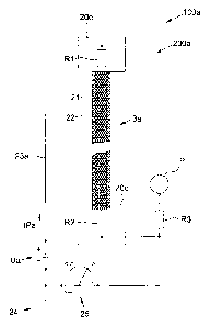
Fig. 2 shows diagrammatically a monitoring device 200a in an elevator system
100a. Connected to the ends of a suspension-and-traction means 3a, which
consists
essentially of a cord 21 and a sheath 22 that largely surrounds this cord 21,
are contacting
elements 20c and 20d respectively. These contacting elements 20c and 20d
preferably
each have integrated in them a resistor R1, R2 respectively, to which a test
circuit 23a,
with a voltage source Ua and a test-current Ipa, can be applied. Further, this
test circuit
23a has a grounding 24 and a measurement apparatus 25, as well as an optional
connection
to a contact point P ¨ for example a return pulley, over which the suspension-
and-traction
means 3a passes ¨ with a third resistor R3. The resistors R1-R3 have mutually
differing
current and resistance characteristics so that, depending on a respective
incidence of
damage, the measurement apparatus 25 measures a classified measurement value
that
allows a diagnosis, and/or a graded warning message, and/or a shutdown of the
elevator
system 100a. The test circuit 23a can alternatively also be passed only over a
contacting
of the ends of the cord 21 and the contact point P. In this manner, damaged
points in the
suspension-and-traction means can be easily detected. The grounding 24 can
also take
place at another suitable point. So, for example, the contact point P can be
connected
directly to ground. By this means also, a plurality of contact points can be
defined in the
elevator system, each of which alone can detect defective spots in the
suspension-and-
traction means.
12
CA 02778870 2012-04-24
Symbolically shown in Fig. 2a is a monitoring device 200a' in an elevator
system
100a'. In contrast to the monitoring device 200a and the elevator system 100a
of Fig. 2, a
suspension-and-traction means 3' has two cords 21' and 21" which are
surrounded by a
sheath 22'. A corner and/or a side of the elevator car 2 is shown in
perspective and
symbolically so that, for example, it can be seen that the suspension-and-
traction means 3'
¨ and preferably a second, not further shown suspension-and-traction means
passes on the
opposite side of the elevator car 2 ¨ passing under the elevator car 2 over
two return and/or
suspension pulleys 27a and 27b. These return and/or suspension pulleys 27a and
27b form
two optionally available contact points P1 and P2, which ¨ shown symbolically
¨ are
connected to resistors RP' and RP" respectively.
As already disclosed, at their respective ends, the cords 21' and 21" are
preferably
also advantageously connected to resistors RCa and RCa' for the cord 21', and
to resistors
RCb and RCb' for the cord 21". The characteristics of the resistors RCa, RCa',
RCb and
RCb', as well as optionally the resistors RP', RP", all mutually differ, or
the resistors RCa,
RCb and RCa', RCb' at the ends of the cords 21' and 21" are arranged mirror-
inverted in
relation to their characteristics. In other words, the characteristics of the
resistors RCa and
RCb' and/or RCb and RCa' can also be identical. The ends of the suspension
means are
connected via the respective resistance elements RCa and RCb' and/or RCb and
RCa' to
the measurement apparatus 25'.
Furthermore, in this Fig. 2a, at the optional contact point Pl, the incidence
of
damage of a cross-circuit Qsch is represented symbolically, in that it is
outlined that the
cords 21' and 21" no longer sit at a distance from each other in the sheath
22' but, for
example, through a sheath 22' that has become damaged, become so close to each
other
that they enter into contact with each other.
The incidence of damage of an impending cord break Cb is symbolically shown at
the also optional contact point P2. The cord 21' begins to unravel its
individual strands 26
that protrude from the sheath 22' and thereby cause a contact at the return or
suspension
pulley 27b, or at its support. Self-evidently, monitoring of the contact
points Pl, P2 in the
manner shown can also take place without resistors RCa, RCa', RCb and RCb'.
Shown diagrammatically in Fig. 3 is another variant embodiment of a monitoring
device 200b for an outlined elevator system 100b. A suspension-and-traction
means 3b
has four cords 21a-21d which are jointly surrounded by a sheath 22a. Arranged
at the
respective ends of each of the cords 21a-21d are contacting elements 20e and
20f.
13
CA 02778870 2012-04-24
Integrated in each of these contacting elements 20e and 20f are four resistors
R1', R3', R5',
R7' and R2', R4', R6', R8' respectively, which are connected to a test circuit
23b with a
voltage source Ub, a test-current IPb, a grounding 24', and a measurement
apparatus 25a.
Furthermore, an optional contact point P' with a resistor R9' is connected to
the test circuit
23b.
The resistors R1'-R9' all have different current characteristics, or are
optionally
arranged mirror-inverted. In other words, for example, the resistor R1' can
have a current
characteristic w, the resistor R3' a current characteristic x, the resistor
R5' a current
characteristic y, and the resistor R7' a current characteristic z, while the
resistor R2' has the
current characteristic z, the resistor R4' the current characteristic y, the
resistor R6' the
current characteristic x, and the resistor R8' the current characteristic w.
The sums w + z,
x + y, y + x, z + w and also w+x+y+z at the one adjacent ends of the cords 21a-
21d,
and z+y+x+w at the other adjacent ends, are identical. The current
characteristic of the
resistor R9' is different than w, x, y or z.
Shown diagrammatically in Fig. 4 is a further variant embodiment of a
monitoring
device 200c for an outlined elevator system 100c with a suspension-and-
traction means 3c.
The suspension-and-traction means 3e has 12 cords 21a'-211', which are all
jointly
surrounded by a sheath 22b. Arranged at the one adjacent ends of the cords
21a'-211' is a
contacting element 20g, in which resistors R1", R3", R5", R7", R9", R11",
R13", R15",
R17", R19", R21" and R23" are preferably integrated, each individual resistor
being
assigned to one of the cords 21a'-211'. Arranged at the other adjacent ends of
the cords
21a'-211' is a second contacting element 20h, in which, similar to the first
contacting
element 20g, resistors R2", R4", R6", R8", R10", R12", R14", R16", R18", R20",
R22" and
R24" are preferably integrated, each of which is also assigned to one of the
cords 21a'-211'.
Similar to Fig. 3, the resistors R1"-R24" are connected to a test circuit 23c
with a
test-current IPc. The test circuit 23c has further a voltage source Uc, a
grounding 24", and
a measurement apparatus 25b. Also connected to the test circuit 23c is again
an optional
contact point P" with a resistor R25".
Also similar to Fig. 3, the resistors R1"-R23" with odd reference numbers in
relation to their current characteristics are preferably arranged mirror-
inverted to the
resistors R2"-R24" with even reference numbers. The resistor R25", on the
other hand, is
preferably chosen different again from these twelve current characteristics.
14
CA 02778870 2012-04-24
The grounding 24 can, as described in the example of Fig. 2, be arranged at
any
point of the system. Thus, the contact point P can be connected directly to
ground.
Therefore, contact points can also be defined in the elevator system that,
each by itself, in
interaction with the monitoring device, can detect defective points in the
suspension-and-
traction means.
CA 02778870 2012-04-24
Reference symbols
1 ¨ Elevator hoistway
2 ¨ Elevator car
3, 3', 3a-3c ¨ Suspension-and-traction means
4 ¨ Counterweight
¨ Traction sheave
6 ¨ Drive unit
7a-7c ¨ Gui derail
8 ¨ Top hoistway door
9 ¨ Hoistway door
¨ Hoistway door
11 ¨ Bottom hoistway door
12 ¨ Machine room
13 ¨ Hoistway ceiling
14¨ Hoistway floor
15a, 15b ¨ Hoistway side wall
16a, 16b ¨ Loeationally-fixed fastening point, suspension-means hitch-point
17 ¨ Suspension pulley for 4
18a, 18b ¨ Return pulley, suspension pulley for 2
19a-19c ¨ Hoistway-floor buffer
20a-20h ¨ Contacting element
21, 21', 21", 21a-21d, 21a'-211' ¨ Cord
22, 22', 22a, 22b ¨ Sheath
23, 23a-23c ¨ Test circuit
24, 24', 24" ¨ Grounding
25, 25', 25a, 25b ¨ Measurement apparatus
26 ¨ Individual strand
27a, 27b ¨ Return or suspension pulley
100, 100a, 100a', 100b, 100c ¨ Elevator system
200, 200a, 200a', 200b, 200c ¨ Monitoring device
Cb ¨ Cord break
16
CA 02778870 2012-04-24
P, P', P", PI, P2 ¨ Contact point, return pulley
IP, IPa-IPc ¨ Test current
Qsch - Cross-circuit
R1-R3, R1'-R9', R1"-R25", RCa, RCa', RCb, RCb', RP', RP" ¨ Resistor,
electronic
component, capacitor, coil
U, Ua - Uc ¨ Voltage source
17