Language selection

Search

Patent 2778882 Summary

Third-party information liability

Some of the information on this Web page has been provided by external sources. The Government of Canada is not responsible for the accuracy, reliability or currency of the information supplied by external sources. Users wishing to rely upon this information should consult directly with the source of the information. Content provided by external sources is not subject to official languages, privacy and accessibility requirements.

Claims and Abstract availability

Any discrepancies in the text and image of the Claims and Abstract are due to differing posting times. Text of the Claims and Abstract are posted:

  • At the time the application is open to public inspection;
  • At the time of issue of the patent (grant).
(12) Patent: (11) CA 2778882
(54) English Title: WHEEL NUT ASSEMBLY
(54) French Title: ENSEMBLE D'ECROUS DE ROUES
Status: Granted
Bibliographic Data
(51) International Patent Classification (IPC):
  • B60B 3/16 (2006.01)
  • B60B 23/06 (2006.01)
  • B60B 25/20 (2006.01)
  • F16B 39/08 (2006.01)
  • F16B 41/00 (2006.01)
(72) Inventors :
  • FERMAN, MICHAEL (Australia)
  • KRATZER, OLIVER CLEMENS ROBERT (Australia)
  • BERENGUT, JON (Australia)
(73) Owners :
  • FERMAN, MICHAEL (Australia)
(71) Applicants :
  • FERMAN, MICHAEL (Australia)
(74) Agent: OSLER, HOSKIN & HARCOURT LLP
(74) Associate agent:
(45) Issued: 2020-04-07
(86) PCT Filing Date: 2010-11-12
(87) Open to Public Inspection: 2011-05-19
Examination requested: 2015-09-14
Availability of licence: N/A
(25) Language of filing: English

Patent Cooperation Treaty (PCT): Yes
(86) PCT Filing Number: PCT/AU2010/001507
(87) International Publication Number: WO2011/057337
(85) National Entry: 2012-04-25

(30) Application Priority Data:
Application No. Country/Territory Date
2009905537 Australia 2009-11-13

Abstracts

English Abstract


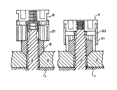
A wheel nut assembly for fixing a wheel to a vehicle hub which includes a
wheel nut
with an internal thread; a wheel stud having an external thread to cooperate
with the
internal thread of said wheel nut and having an end portion adapted to project

beyond the wheel nut which end portion includes axial grooves or ribs on its
external
surface; a retaining cap with internal grooves or ribs complementary to the
external
grooves or ribs on said wheel stud adapted to fit over said wheel stud and
said wheel
nut; and means to secure the retaining cap to said wheel nut. The retaining
cap
prevents rotation of the nut once it has been tightened.


French Abstract

La présente invention concerne un ensemble d'écrous de roues pour la fixation d'une roue à un moyeu de véhicule comportant un écrou de roue à filetage intérieur; un goujon de roue à filetage extérieur pour coopérer avec le filetage intérieur dudit écrou de roue et présentant une partie d'extrémité apte à se prolonger au-delà de l'écrou de roue, ladite partie d'extrémité comprenant des rainures ou nervures axiales sur sa surface extérieure; un capuchon de retenue avec des rainures ou nervures intérieures complémentaires aux nervures ou rainures extérieures sur ledit goujon de roue apte à être fixé sur ledit goujon de roue et ledit écrou de roue; et un moyen pour fixer le capuchon de retenue au dit écrou de roue. Le capuchon de retenue interdit la rotation de l'écrou une fois qu'il est serré. Selon certains modes de réalisation, un couvercle esthétique est prévu pour améliorer l'aspect de la roue. Ce couvercle esthétique peut également être utilisé pour bloquer le capuchon de retenue avec l'écrou et fournir une indication que l'écrou est solidement fixé.

Claims

Note: Claims are shown in the official language in which they were submitted.


8
The embodiments of the present invention for which an exclusive property or
privilege is claimed are defined as follows:
1. A wheel nut assembly for fixing a wheel to a vehicle hub, the wheel nut
assembly comprising:
a wheel nut with an internal thread;
a wheel stud having an external thread to co-operate with the internal
thread of said wheel nut and having an end portion adapted to project beyond
the wheel nut which end portion has an axial surface and includes axial
grooves or ribs on the external surface;
a retaining cap secured to the wheel nut, said cap having internal
grooves or ribs complementary to the axial grooves or ribs on said wheel stud
and adapted to fit over said wheel stud and adapted to cover said wheel nut
after the wheel nut is fastened to said stud and activated by a spring to
uncover said nut to enable removal of the nut and the cap as one connected
unit from said stud.
2. The wheel nut assembly as claimed in claim 1, the cap comprising a first

component and a second component which are lockable together, the first
component engaging the nut and the second component engaging the end
portion of the stud.
3. The wheel nut assembly as claimed in claim 1, further comprising an
aesthetic cover to fit over the retaining cap.
4. The wheel nut assembly as claimed in claim 1, for fixing a wheel to a
vehicle
hub, wherein:
the wheel nut incorporates an axially extending cylindrical wall
extending above the internal thread of the nut;
and the end portion of said stud adapted to project into a space
defined by the axially extending cylindrical wall; and
the assembly includes a ratchet arm resiliently urged against the axial
grooves or ribs on said stud and an unlocking mechanism associated with
said ratchet arm to disengage said ratchet arm from the axial grooves or ribs
of said stud.

9
5. The wheel nut assembly as claimed in claim 4, wherein the unlocking
mechanism is configured such that pressure applied against the force of a
spring and rotation to a position that disengages the ratchet arm from the
axial grooves or ribs of the stud enables the nut to be turned for removal.
6. A nut retaining mechanism for use in the wheel nut assembly of claim 1,
the
nut retaining mechanism comprising a ratchet arm resiliently urged against
the axial grooves or ribs on said stud and an unlocking mechanism
associated with said ratchet arm to disengage said ratchet arm from the axial
grooves or ribs of said stud.
7. The nut retaining mechanism as claimed in claim 6, wherein the unlocking

mechanism is configured such that pressure applied against the force of a
spring and rotation to a position that disengages the ratchet arm from the
axial grooves or ribs of the stud enables the nut to be turned for removal.
8. A wheel nut and retaining cap assembly for fixing a wheel to a vehicle
hub,
the assembly comprising:
a wheel nut secured to a retaining cap for the wheel nut, said retaining
cap having internal grooves or ribs complementary to external grooves or ribs
on a wheel stud and adapted to fit over said wheel stud and adapted to cover
said wheel nut after the wheel nut is fastened to said stud and activated by a

spring to uncover said nut to enable removal of said wheel nut and retaining
cap assembly as one=connected unit from said stud.

Description

Note: Descriptions are shown in the official language in which they were submitted.


CA 02778882 2012-04-25
WO 2011/057337
PCT/AU2010/001507
1
WHEEL NUT ASSEMBLY
This invention relates to wheel nuts for retaining vehicle wheels on the wheel
hub
and for ameliorating the risk of the nuts becoming loose.
Background to the invention.
In order to prevent wheel nuts loosening one approach has been to provide a
stud
for the nut that has an internal thread of opposite hand to the thread of the
nut. Such
an arrangement is disclosed in USA patent 6916144.
Another proposal, is to use a compression collar for the nut as in USA patent
6935825.
In these arrangements it is important to have tamper proof nut assembly that
visibly
indicates that the nut is tightened. In addition it is usual to provide an
aesthetic cap
or cover for the nut.
It is an object of this invention to provide a tamper evident wheel nut
arrangement
that also enables the provision of a variety of aesthetic appearances.
Brief description of the invention
To this end the present invention provides a wheel nut assembly for fixing a
wheel
to a vehicle hub which includes
a wheel nut assembly for fixing a wheel to a vehicle hub which includes
a wheel nut with an internal thread;
a wheel stud having an external thread to co-operate with the internal thread
of said
wheel nut and having an end portion adapted to project beyond the wheel nut
which
end portion includes axial grooves or ribs on its external surface;
a retaining cap for the wheel nut, said cap having internal grooves or ribs
complementary to the external ribs or grooves on said wheel stud adapted to
fit over
said wheel stud and secure said wheel nut;
and means to secure the retaining cap to said wheel nut.
In this arrangement the retaining cap prevents rotation of the nut once it has
been
= tightened. In some embodiments an aesthetic cover is provided to improve
the
appearance of the wheel. This aesthetic cover may also be used to lock the
retaining cap to the nut and provide an indication that the nut is securely
fastened.

CA 02778882 2012-04-25
WO 2011/057337
PCT/AU2010/001507
2
Any suitable means may be provided to secure the retaining cap to the nut.
Preferably the cap consists of two components which are lockable together, one

component engaging the nut and the second component engaging the end of the
stud.
In a preferred embodiment a ratchet mechanism is used to secure the nut. In
this
embodiment there is provided a wheel nut assembly for fixing a wheel to a
vehicle
hub which includes
a wheel nut with an internal thread and an axially extending cylindrical wall
extending above the nut;
a wheel stud having an external thread to co-operate with the internal thread
of said
wheel nut and having an end portion adapted to project beyond the wheel nut
into
the space defined by the axially extending cylindrical wall the end portion of
said
stud includes axial ribs on its external surface;
a nut retaining mechanism which includes a ratchet arm resiliently urged
against
said ribs on said stud and an unlocking mechanism associated with said ratchet

arm to disengage said ratchet arm from the ribs of said stud.
Preferably the unlocking mechanism requires pressure to be applied against the

force of a spring and rotation to a position that disengages the ratchet arm
from the
ribs of the stud to enable the nut to be turned for removal.
Detailed description of the invention
Various embodiments of the invention will be described with reference to the
drawings in which
Figure 1 illustrates a cross sectional view of the latched position of a first
embodiment;
Figure 2 illustrates a cross sectional view of the unlatched position of the
embodiment of figure 1;\
Figure 3 illustrates a cross sectional view of the latched position of a
second
embodiment;
Figure 4 illustrates a cross sectional view of the unlatched position of the
embodiment of figure 3;
Figure 5 is an exploded view of the embodiment of figures 2 and 3;

CA 02778882 2012-04-25
WO 2011/057337
PCT/AU2010/001507
3
Figure 6 illustrates a cross sectional view of the latched position of a third
embodiment;
Figure 7 illustrates a cross sectional view of the unlatched position of the
embodiment of figure 63;
Figure 8 is an exploded view of the embodiment of figures 6 and 7;
Figure 9 illustrates a cross sectional view of the latched position of a
fourth
embodiment;
Figure 10 illustrates a cross sectional view of the unlatched position of the
embodiment of figure 9;
Figure 11 is an exploded view of the embodiment of figures 9 and 10;
Figure 12 illustrates a cross sectional view of the latched position of a
fifth
embodiment;
Figure 13 illustrates a cross sectional view of the tool unlatching and the
unlatched
position of the embodiment of figure 12;
Figure 14 is an exploded view of the embodiment of figures 12 and 13;
Figure 15 illustrates a cross sectional view of the latched position of a
sixth
embodiment;
Figure 16 illustrates a cross sectional view of the unlatched position of the
embodiment of figure 15;
Figure 17 is an exploded view of the embodiment of figures 15and 16;
Figure 18 illustrates a cross sectional view of the latched position of a
seventh
embodiment;
Figure 19 illustrates a cross sectional view of the unlatched position of the
embodiment of figure 18;
Figure 20 is an exploded view of the embodiment of figures 18and 19;
Figure 21 illustrates a cross sectional view of the latched position of an
eighth
embodiment;
Figure 22 illustrates a cross sectional view of the unlatched position of the
embodiment of figure 21;
Figure 23 is an exploded view of the embodiment of figures 21and 22;
Figure 24 illustrates a crosssectional view of a ninth embodiment;
Figure 25 is an exploded view of the components of the figure 24 embodiment;
Figure 26 is a view of a tenth embodiment;

4
Figure 27 is an exploded view of the components of the embodiment of figure
26;
Figures 28 to 30 illustrate the operation of the embodiment of figure 26;
Figure 31 is an exploded view of the components of an eleventh embodiment;
Figures 32 and 33 illustrate the operation of the embodiment of figure 31.
In all embodiments the wheel hub 1 is secured to the alloy wheel rim 2 by the
stud 3
and its associated wheel nut 6. The stud 3 has helical threads 4 that
cooperate with
corresponding threads 7 on the internal surface of nut 6. The stud 3 extends
beyond
the nut 6 and on this portion has splines 5. The retainer cap 8 fits over the
nut 6 and
snugly to the upper portion of the stud 3. The upper portion of the retaining
cap 8
includes grooves 9 corresponding to the splines 5 of stud 3.
In the embodiment of figures 1 and 2 the retaining cap 8 is biased against the
nut 6
by a spring 11 and is pressed downwards by the action of the cover 12 which
itself
is biased against cap 8 by a spring 13, the cover 12 includes an opening 14
shaped
to cooperate with a cross member 15 in the stud 3. Rotation of the cover 12
when it
is pressed down locks it onto the cross member 15. A colour panel 16 on the
retaining cap 8 indicates that the cap is not locked if it is visible.
In the second embodiment of figures 3 to 5 the retaining cap 8 is surrounded
by a
cylindrical cover 21 and includes recesses 22 to accommodate spring biased
blocks 23 which engage stud 3 below the splines 5 when they are locked in
position
by the cover 21. This arrangement is suitable where there is a fixed extension
of the
stud.
In the third embodiment of figures 610 8 the stud 3 has a hollow stem 31 at
its
remote end which includes a spring biased core 32 with a groove 33 for
engaging a
ball 34 that seats within a hole 35 in the upper wall of the stud. The upper
portion of
the retaining cap 8 includes a groove 36 that also engages the ball 34. An
external
spring 37 biases the cap 8 away from the nut 6. This is a compact design.
Figures 9 to 11 illustrate a fourth embodiment utilising a push pull
arrangement. The
retaining cap 8 has radial grooves 41 for balls 42 that engage a grooved
recess 43 in
the upper part of stud 3. Two pins 44 arranged concentrically with stud 3 bias
the
balls 42. A cover 45 encloses the retaining cap 8. Rotation of the cover 45
locks the
cover and retaining cap against the bias of spring 46 located at the upper end
of cap
8 and against the top of cover 45. The spring 47 acts between the wheel rim 2
and
the cap 8.
CA 2778882 2019-01-04

5
Another mechanism is illustrated in a fifth embodiment which uses a tool to
unlock
the retaining cap as shown in figures 12-14. A C clip 52 is inserted from
below in to
the retaining cap 8 and is stopped from rotating by a spring pin 53. The C
clip 52
engages grooves in the splined portion of the stud 3. A spring 56 is placed
externally of the cap 8 between flange 55 and the rim 2. The tool 57 releases
C clip
to unlock the assembly.
The sixth embodiment illustrated in figures 15-17 uses a custom nut with
recesses
61 in its corners to engage balls 62 carried in holes 63 of the retaining cap
8. A
cover 64 has associated spring plugs 65 that are inserted in radial holes in
the
retaining cap.
The seventh embodiment shown in figures 18-20 uses a spring loaded pin 71
arranged in a passage 72 in the retaining cap 8 that pushes a ball 73 into
engagement with a groove 74 in the splined end of the stud 3. A spring 76 is
placed
externally of the cap 8 between flange 75 and the rim 2.
Figures 21-23 illustrate an eighth embodiment that utilises a custom nut
design with
a cut out portion 81 to accept a plug 82 for locking. The cap 8 also has a cut
out 83
corresponding with that in the nut 6. A cylindrical cover 86 seats under
flange 85 of
cap 8. A spring retaining pin 87 may be used to secure the cover 86 to cap 8.
In the ninth embodiment shown in figures 24 and 25 a custom nut 6 is used
which
has recesses 91 for the balls 92. The balls 92 sit in holes 93 in the side
wall of the
retaining cap 8. A spring 94 is located internally of the cap 8 to bias the
cap 8 away
from nut 6. A cylindrical cover 95 encloses the retaining cap 8. A spring 96
seats on
the outside of the upper portion of the cap 8 to bear against the clutch ring
97 that
lies underneath the top of cover 95. A key 98 is used to depress and turn the
clutch
ring 97 so that the cover 95 is locked to the cap 8. An 0 ring 99 provides a
seal
between lower edge of the cover 95 and the lower edge of the cap 8. The clutch
ring
97 provides a seal at the top to prevent dirt entering under cover 95. The cap
8 may
carry a decorative cover 100.
In the tenth embodiment shown in figures 26-30 the nut 6 and custom stud 3 are
the
same. The nut includes recesses 119 for locking balls 110. The cap or socket
lock
8 seats around the nut and the ejector spring 111 sits within cap 8 on top of
the nut
6. The outer surface of the cap or socket lock includes splines or ribs 120.
The spline
lock 113 engages the splines on the end of stud 3 and also engages the spline
120
CA 2778882 2019-01-04

6
of cap 8. The nut spring 112 lies between the spline lock 113 and the cap 8.
On top
of the spline lock is a disc 115 that sits on the lock spring 114 which is
held within
the spline lock 113. The rotary lock 116 extends over the disc 115 and the
spring
114 to abut an outer rim of the spline lock 113. The cover 117 encloses all
the
components including the locking balls 110 which are held in holes in the wall
of cap
8 as best seen in figures 28-30.
The ratio of the faces on the nut 6 and the splines on the stud 3 and the
splines
120 on cap 8 ensure that only a slight turning of the assembly is needed as it
is
pressed down to align the faces and splines.
The assembled wheel lock is fitted as shown in figures 28-30. In figure 28 the

assembly sits on the tightened nut 6. In figure 29 the assembly has been
pushed
down to compress the ejector spring 111. As the assembly is pushed down it is
turned slightly so that the internal hexagon faces of cap 8 engages the faces
of wheel
nut 6 and the locking balls are held in the recesses 119 of the nut 6. In
figure 30 the
assembly is pushed down further and again turned slightly so that the spline
lock
113 engages the splines on the end of stud 3 and splines 120 on cap 8. The
socket
lock or cap 8 now engages with the spline lock 113 and the balls 110 are
locked into
the recesses 119 on nut 6. Using the key 118 the rotary lock 116 is turned
which
locks the entire assembly together and to the stud and nut.
Figures 31 to 33 illustrate an eleventh embodiment which uses a ratchet
mechanism
to secure the retaining cap to the wheel nut and provides a visual indication
of the
lock status of the wheel nut. The stud 3 is the same as in prior embodiments.
The
nut 121 includes a circumferential cover extending above the nut to
accommodate
the ratchet locking mechanism. The custom screws 128 secure the ratchet sleeve

124 to the nut 121.
The ratchet mechanism consists of pawls 125 that engage with the splines on
the
end of stud 3 when biased by the spring 126. The ring 127 holds the pawls 125
and
spring 126 in position. The spring 129 seats on the ring 127 and the 0 rings
130 and
131 are positioned above and below the ratchet sleeve 124. The knob 132
engages
with the internal rim of the ratchet sleeve 124.
In figure 32 view A shows that as the nut is tightened the pawls engage the
spline
and prevent the nut from coming loose. View B provides a detailed view and
view C
is a section view along z-z of view A.
CA 2778882 2019-01-04

CA 02778882 2012-04-25
WO 2011/057337
PCT/AU2010/001507
7
Figure 33 illustrates the removal of the nut. In view A the knob 132 is pushed
down
and rotated a quarter turn in direction A . View B provides a detailed view
and view
C is a section view along z-z of view A. The top assembly is retained by the 3

screws 128 engaging in the bayonet guides in ratchet sleeve 124. The top
assembly
is under constant tension by spring 129. The top assembly disengages the pawls

125 from the splines on stud 3 and the nut can be removed by rotation in
direction B
of view A.
Those skilled in the art will realise that this invention provides a unique
and less
expensive means of ensuring that a wheel nut is securely fastened to the wheel

hub. Those skilled in the art will also realise that this invention may be
implemented
in embodiments other than those described without departing from the core
teachings of the invention.

Representative Drawing
A single figure which represents the drawing illustrating the invention.
Administrative Status

For a clearer understanding of the status of the application/patent presented on this page, the site Disclaimer , as well as the definitions for Patent , Administrative Status , Maintenance Fee  and Payment History  should be consulted.

Administrative Status

Title Date
Forecasted Issue Date 2020-04-07
(86) PCT Filing Date 2010-11-12
(87) PCT Publication Date 2011-05-19
(85) National Entry 2012-04-25
Examination Requested 2015-09-14
(45) Issued 2020-04-07

Abandonment History

There is no abandonment history.

Maintenance Fee

Last Payment of $263.14 was received on 2023-11-09


 Upcoming maintenance fee amounts

Description Date Amount
Next Payment if standard fee 2024-11-12 $347.00
Next Payment if small entity fee 2024-11-12 $125.00

Note : If the full payment has not been received on or before the date indicated, a further fee may be required which may be one of the following

  • the reinstatement fee;
  • the late payment fee; or
  • additional fee to reverse deemed expiry.

Patent fees are adjusted on the 1st of January every year. The amounts above are the current amounts if received by December 31 of the current year.
Please refer to the CIPO Patent Fees web page to see all current fee amounts.

Payment History

Fee Type Anniversary Year Due Date Amount Paid Paid Date
Application Fee $400.00 2012-04-25
Maintenance Fee - Application - New Act 2 2012-11-13 $100.00 2012-11-07
Maintenance Fee - Application - New Act 3 2013-11-12 $100.00 2013-11-08
Maintenance Fee - Application - New Act 4 2014-11-12 $100.00 2014-11-04
Request for Examination $800.00 2015-09-14
Maintenance Fee - Application - New Act 5 2015-11-12 $200.00 2015-09-14
Maintenance Fee - Application - New Act 6 2016-11-14 $200.00 2016-11-09
Maintenance Fee - Application - New Act 7 2017-11-14 $200.00 2017-11-09
Maintenance Fee - Application - New Act 8 2018-11-13 $200.00 2018-11-12
Maintenance Fee - Application - New Act 9 2019-11-12 $200.00 2019-11-12
Final Fee 2020-02-14 $300.00 2020-02-13
Maintenance Fee - Patent - New Act 10 2020-11-12 $250.00 2020-11-10
Maintenance Fee - Patent - New Act 11 2021-11-12 $255.00 2021-11-11
Maintenance Fee - Patent - New Act 12 2022-11-14 $254.49 2022-11-10
Maintenance Fee - Patent - New Act 13 2023-11-14 $263.14 2023-11-09
Owners on Record

Note: Records showing the ownership history in alphabetical order.

Current Owners on Record
FERMAN, MICHAEL
Past Owners on Record
None
Past Owners that do not appear in the "Owners on Record" listing will appear in other documentation within the application.
Documents

To view selected files, please enter reCAPTCHA code :


To view images, click a link in the Document Description column. To download the documents, select one or more checkboxes in the first column and then click the "Download Selected in PDF format (Zip Archive)" or the "Download Selected as Single PDF" button.

List of published and non-published patent-specific documents on the CPD .

If you have any difficulty accessing content, you can call the Client Service Centre at 1-866-997-1936 or send them an e-mail at CIPO Client Service Centre.


Document
Description 
Date
(yyyy-mm-dd) 
Number of pages   Size of Image (KB) 
Final Fee 2020-02-13 1 42
Representative Drawing 2020-03-16 1 16
Cover Page 2020-03-16 1 49
Maintenance Fee Payment 2020-11-10 1 33
Maintenance Fee Payment 2021-11-11 1 33
Maintenance Fee Payment 2022-11-10 1 33
Abstract 2012-04-25 1 68
Claims 2012-04-25 2 81
Drawings 2012-04-25 23 614
Description 2012-04-25 7 356
Representative Drawing 2012-06-21 1 13
Cover Page 2012-07-18 2 53
Claims 2017-02-22 2 67
Examiner Requisition 2017-05-29 3 196
Amendment 2017-06-22 6 217
Claims 2017-06-22 2 67
Examiner Requisition 2017-09-28 3 140
Maintenance Fee Payment 2017-11-09 1 33
Amendment 2018-03-02 29 717
Description 2018-03-02 7 341
Drawings 2018-03-02 24 531
Examiner Requisition 2018-07-04 4 277
Amendment 2019-01-04 13 448
Description 2019-01-04 7 320
Abstract 2019-01-04 1 14
Claims 2019-01-04 2 68
Fees 2014-11-04 1 42
Fees 2012-11-07 1 44
PCT 2012-04-25 2 77
Assignment 2012-04-25 4 107
Abstract 2019-08-14 1 14
Fees 2013-11-08 1 42
Maintenance Fee Payment 2015-09-14 1 44
Request for Examination 2015-09-14 1 42
Examiner Requisition 2016-08-25 3 175
Maintenance Fee Payment 2016-11-09 1 41
Amendment 2017-02-22 5 169
Maintenance Fee Payment 2023-11-09 1 33