Note: Descriptions are shown in the official language in which they were submitted.
CA 02779231 2011-10-27
WO 2010/127441 PCT/CA2010/000678
OPTIMIZING A SERVING GATEWAY LOCATION IN A HOME EVOLVED
NODE B WITH LOCAL IP ACCESS
FIELD OF THE INVENTION
This invention relates to femto cell networks, and more particularly to a
system and method of optimizing a server gateway location for home evolved
Node-B
("eNB") devices having local Internet Protocol access.
BACKGROUND OF THE INVENTION
Wireless carriers employ cellular towers to establish large cells for wireless
communications over vast physical areas, such as metropolitan or rural areas.
The
large cells or macro cells may cover areas of lkrn to 5km in diameter. A
cellular
tower broadcasts wireless signals to and receives wireless signals from user
equipment or mobile handsets that are located throughout the macro cells.
Various structures are located within the macro cell environment that
obstruct,
reflect or otherwise interfere with the wireless signals. For example, users
typically
attempt to use mobile devices inside structures such as homes and commercial
establishments, among other structures. These structures may be constructed of
high
loss material, such as concrete or metal that block wireless signals from
penetrating
the structures. Reception within these structures is often poor and unreliable
due to
weak wireless signal strength. Poor reception is associated with inferior
quality of
service by the mobile user. Femto cells or micro cells are located within
these high
loss structures to route signal transmissions through existing broadband
backhaul
infrastructure to the macro network. Data may be transported wirelessly
between the
femto cells and the macro cells via a macro Serving Gateway ("SGW") and a
local
packet data network gateway ("PGW") using an Si-U interface. In this case, the
data
travels outside the femto cell to the macro SGW and back inside the femto cell
to the
local PGW. This is known a traffic tromboning and is undesirable because it
adds
latency to data communications.
What is desired are systems and methods of optimizing a Serving Gateway
location associated with femto cells. It is also desired to have systems and
methods of
avoiding traffic tromboning on a Si-U interface and avoiding frequent Serving
Gateway relocation between a home premises and a macro environment during
interrupted coverage at the home premises.
1
CA 02779231 2014-10-27
SUMMARY OF THE INVENTION
The present invention advantageously provides a method and system for
optimizing a location of the serving gateway on a local network or a macro
network
based on a status mode of the user equipment and a location of the user
equipment.
The invention provides a system for enabling a mobile device to establish IP
access
on a packet data network connection using a femto cellular access network. A
femto
cellular access network is provided and is communicatively coupled to a local
server
gateway and a macro server gateway. A mobility manager is communicatively
coupled to the femto cellular access network and is in communication with the
local
server gateway and the macro server gateway. The mobility manager obtains a
status
mode of the mobile device and a location of the mobile device transmitted on
the
femto cellular access network. The mobility manager selects one of the local
server
gateway and the macro server gateway based on the status mode of the mobile
device
and the location of the mobile device.
According to another embodiment, the invention provides a system,
comprising: a mobility manager configured to communicatively couple to a femto
cellular access network and configured to communicate with a local server
gateway
and a macro server gateway, wherein the mobility manager is configured to:
obtain a
status mode of a mobile device and a location of the mobile device transmitted
on the
femto cellular access network; and select one of the local server gateway and
the
macro server gateway for the mobile device based on the status mode of the
mobile
device and the location of the mobile device; wherein the local server gateway
and
the macro server gateway are configured to communicatively couple to the femto
cellular access network.
According to another embodiment, the invention provides a system for
enabling a mobile device that is coupled to a macro cellular network to
establish an IP
access on a packet data network connection using a femto cellular access
network.
The macro cellular access network is communicatively coupled to a local server
gateway and a macro server gateway. A mobility manager is communicatively
coupled to the macro cellular access network and is in communication with the
local
server gateway and the macro server gateway. The mobility manager obtains a
status
mode of the mobile device and a location of the mobile device transmitted on
the
2
CA 02779231 2014-10-27
macro cellular access network. The mobility manager selects one of the local
server
gateway and the macro server gateway based on the status mode of the mobile
device
and the location of the mobile device.
According to another embodiment, the invention provides a mobile device
configured to communicatively couple to a femto cellular access network and
configured to: utilize a local server gateway to access a packet data network
in
response to operating in a first mode at a particular location; and utilize a
macro
server gateway to access a packet data network in response to operating in a
second
mode at the particular location; wherein the local server gateway and the
macro
server gateway are communicatively coupled to the femto cellular access
network.
According to another embodiment, the invention provides a method,
comprising: determining a status of a mobile device; determining a location of
the
mobile device; communicating with a local server gateway and a macro server
gateway; and selecting one of the local server gateway and the macro server
gateway
to provide IP access to the mobile device on a packet data network connection
based
on the status of the mobile device and the location of the mobile device.
According to yet another embodiment, the invention provides a method of
using a femto cell to establish IP access for a mobile device on a packet data
network
connection using one of a local server gateway and a macro server gateway. A
mobility manager determines a status of the mobile device and determines a
location of
the mobile device. The mobility manager communicates with the local server
gateway
and the macro server gateway and selects one of the local server gateway and
2a
CA 02779231 2011-10-27
WO 2010/127441
PCT/CA2010/000678
the macro server gateway based on the status of the mobile device and the
location of
the mobile device.
BRIEF DESCRIPTION OF THE DRAWINGS
A more complete understanding of the present invention, and the attendant
advantages and features thereof, will be more readily understood by reference
to the
following detailed description when considered in conjunction with the
accompanying
drawings wherein:
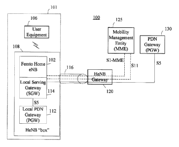
FIG. 1 illustrates a block diagram of an in-home local IP access network
architecture having a local PDN connection and a local PGW, in accordance with
the
principles of the present invention;
FIG. 2 is a block diagram of an away-from-home remote access architecture
having an external PDN connection and a local PGW, in accordance with the
principles of the present invention;
FIG. 3 is a flow diagram of a service flow for relocating a servicing gateway
to a macro environment when user equipment is set to idle mode while located
within
an operating range of a local network, in accordance with the principles of
the present
invention;
FIG. 4 is a block diagram of an in-home local IP access network architecture
having an external PDN connection and an external PGW, in accordance with the
principles of the present invention;
FIG. 5 is a block diagram of an away-from-home remote access architecture
having an external PDN connection and an external PGW, in accordance with the
principles of the present invention;
FIG. 6 is a flow diagram of a service flow for relocating a servicing gateway
between a macro environment and a local environment (or vice versa) when user
equipment activates or de-activates a local PDN connection while in the local
environment, in accordance with the principles of the present invention;
FIG. 7 is a block diagram of an in-home local IP access network architecture
having a local PDN connection and an local PGW, in accordance with the
principles
of the present invention;
3
CA 02779231 2011-10-27
WO 2010/127441
PCT/CA2010/000678
FIG. 8 is a block diagram of an away-from-home remote access architecture
having a local PDN connection and a local PGW, in accordance with the
principles of
the present invention.
DETAILED DESCRIPTION OF THE INVENTION
As is shown in FIG. 1, the invention provides femto base stations or home
evolved Node-B ("e-NB") devices 102 that are positioned inside structures 101
to
improve cellular quality of service and to enable communications with devices
coupled to a home network. For example, the femto base stations 102 may be
positioned inside residential or commercial structures 101, among other
structures.
The femto base stations 102 may operate in the femto power range of about
+15dBm
and may provide an operation range of approximately 50 meters. The invention
also
provides macro e-NBs 202 that are positioned within the macro cell, which is
located
outside the residential or commercial structures.
Some embodiments may be described using the expression "coupled" and
"connected" along with their derivatives. For example, some embodiments may be
described using the term "connected" to indicate that two or more elements are
in
direct physical or electrical contact with each other. In another example,
some
embodiments may be described using the term "coupled" to indicate that two or
more
elements are in direct physical or electrical contact. The term "coupled" or
"communicatively coupled," however, may also mean that two or more elements
are
not in direct contact with each other, but yet still co-operate or interact
with each
other. The embodiments disclosed herein are not necessarily limited in this
context.
The femto base stations 102 and the macro e-NBs 202 communicate with user
equipment ("UE") 106, such as cellular telephone, personal digital assistants,
or other
UE over wireless cellular technologies. The femto base stations 102 may use
existing
broadband backhaul infrastructure to access networks, such as the Internet
and/or
macro networks, through the publicly-switched telephone network. The femto
base
stations 102 may be communicatively coupled to digital subscriber line ("DSL")
devices or cable modems and to local area networks ("LANs") 108.
The invention may operate using existing cellular technologies, such as
CDMA2000 1 xRTT, evolution-data optimized ("EV-DO") and long-term evolution
("LTE") networks, among other cellular networks.
4
CA 02779231 2011-10-27
WO 2010/127441 PCT/CA2010/000678
The UE 106 may include a wide range of electronic devices, including but not
limited to mobile phones, personal data assistants ("PDA") and similar
devices, which
use the various communication technologies such as advanced mobile phone
system
("AMPS"), time division multiple access ("TDMA"), code division multiple
access
("CDMA"), global system for mobile communications ("GSM"), general packet
radio
service ("GPRS"), lx evolution-data optimized (abbreviated as "EV-DO" or "lxEV-
DO") and universal mobile telecommunications system ("UMTS"). The UE 106 also
includes hardware and software suitable to support the control plane functions
needed
to engage in wireless communication with the femto base stations 102 and the
macro
eNBs 202. Such hardware can include a receiver, transmitter, central
processing unit,
storage in the form of volatile and nonvolatile memory, and input/output
devices,
among other hardware.
The invention is directed to deploying a plurality of femto cells 102 within a
macro cell or macro environment. While the various femto base stations 102 are
components of the overall communications network, each femto cell is separate
and
distinct from the existing macro cell and any adjacent femto cells. During
mobility,
the system hands UE communication sessions from a femto cell 102 to the macro
cell,
or vice versa. Alternatively, the system may hand UE communication sessions
from a
femto cell to another femto cell.
According to one embodiment, the macro cells and the femto cells employ
handoff procedures that are initiated for various reasons, including when
signal
strength measurements originating in the active network, such as the cellular
network
or the femto network, fall below pre-selected threshold parameters. The UE 106
may
detect a weak signal strength emanating from the "active" access network and
may
initiate a handoff to the "idle" access network, such as the femto base
station network
or the cellular network, having a stronger signal strength. This may be
performed by
reporting the weak signal to the active access network.
Alternatively, the handoff procedures may be initiated to off-load terminal
device traffic from the cellular network to the femto base station network.
The femto
base station 102 is a personal and dedicated base station for each
corresponding
structure, such as a home or commercial building 101. The femto base stations
102
5
CA 02779231 2011-10-27
WO 2010/127441 PCT/CA2010/000678
independently support network traffic, along with the cellular network that
supports
the macro cell.
The femto base station 102 may be directly or indirectly coupled to a
hub/switch, DSL/cable modem and/or a router (not shown). These devices may
include separate hardware devices or a combination of hardware devices. The
hub/switch and router may be provided to share system resources with the UE
106.
Shared resources may include terminal devices, such as personal computers,
laptops,
printers, and media players, among other terminal devices.
The invention provides the femto base stations 102 having a local packet data
network ("PDN") Gateway ("PGW") 112 with a home access point name ("APN")
and a local Serving Gateway ("SGW") 114 that directs in-home data requests
received
through the local area network 108. A single APN may be assigned to a
plurality of
subscribers and may be resolved to a target local PGW 112. Alternatively, a
plurality
of APNs may be assigned to a plurality of subscribers.
The UE 106 is provided with local IP access on a dedicated packet data
network ("PDN") connection. The PDN connections may include a local PDN
connection, an external PDN connection or both local and external PDN
connections.
The UE 106 may be placed in one of two modes, an active mode and an idle mode.
Depending on the type of local IP access and the state of the UE 106, it is
desirable to
optimize a location of a Serving Gateway (SGW) location, by selectively
assigning
the SGW location into a local environment or a macro environment. The
invention
provides several optimizations. For example, when the UE 106 is placed in idle
mode
while located in a local environment, a mobility management entity ("MME") or
mobility manager may relocate the SGW to the macro environment. When the UE
106 is placed in active mode and is connected through a local PDN connections,
the
MME may relocate the SGW to the local environment to streamline data transport
or
avoid tromboning. When the UE 106 de-activates the local PDN connections while
still engaged to an external PDN connection, the MME may relocate the SGW to
the
macro environment to eliminate frequent SGW relocations due to poor signal
receptions.
Long-term evolution ("LTE") and evolved high rate packet data ("eHRPD")
are exemplary fourth generation ("4G") technologies that improve the universal
6
CA 02779231 2011-10-27
WO 2010/127441 PCT/CA2010/000678
mobile telecommunications system ("UMTS") mobile telephone standard by
providing a simplified, all-packet architecture. The UMTS technology supports
mobile Internet protocol ("IP") services, such as music downloads, video
sharing,
voice over LP broadband access, and other EP services to laptops, personal
digital
assistants ("PDAs") and other user equipment 106. The LTE enhances current
UMTS
capabilities by providing improved efficiency, lower costs, increased peak
data rates,
lower latency, improved services and improved integration with other open
standards.
The invention further supports femto cellular access networks, including an
LTE
network, an EVDO or eHRPD network connected to an evolved packet core ("EPC"),
WiMax 802.16e/m connected to EPC.
It should be appreciated that, although the invention is described with
reference to the LTE network, the principles of the invention may be adapted
by one
of skill in the art to include other networks, such as WiMAX (IEEE 802.16)
networks,
other CDMA2000 networks and any other networks known in the art or later
developed.
Referring now to the drawing figures in which like reference designators refer
to like elements, FIG. 1 illustrates an exemplary block diagram of a system
designated
generally as "100" that provides a local packet data network connection and
includes
UE 106 that communicates on a local area network 108 within a femto cell
located
inside a structure 101. The UE 106 may be assigned a local area IP address.
The
femto base station 102 includes a local packet data network ("PDN") Gateway
("PGW") 112 having a home access point name ("APN") and a local Serving
Gateway ("SGW") 114 that routes in-cell data requests to an in-home LAN 108.
The
'home-based' PDN or local PGW 112 permits the UE 106 to communicate over the
local area network 108.
The local PGW 112 provides the UE 106 with direct connectivity to the
backhaul lP infrastructure using the femto base station 102 and the home LAN
108.
The local PGW 112 and the local SGW 114 eliminate the need to send data from
the
UE 106 across to an operator's macro network. Rather, Internet traffic may be
re-
routed from a service provider's wireless network to the backhaul IP
infrastructure.
The femto base station 102, the local PGW 112 and the local SGW 114 may be
7
CA 02779231 2011-10-27
WO 2010/127441
PCT/CA2010/000678
configured to enable the UE 106 to access one or more packet data networks
("PDN")
concurrently through one or more local PGWs 112.
To support this capability, in addition to supporting a home or local SGW 114
and local PGW 112, the femto base station 102 supports the S5 and Sll
interface,
among other interfaces. The local PGW 112 and the local SGW 114 communicate
using the S5 interface. The femto gateway ("HeNB GW") 120, in addition to
aggregating the S 1-MME interface, also may be enhanced to support Sll and S5
aggregation.
The femto base stations 102 may include a central processing unit ("CPU"),
transmitter, receiver, 1/0 devices and storage, such as volatile and
nonvolatile
memory, to implement the functions described herein. The femto base stations
102
may communicate with the UE 106 over a radio interface.
The femto base station 102 may be coupled to the HeNB GW 120 through
IPsec tunnel 116. IPsec tunnel 116 provides a secure public network connection
and
prevents wiretapping, traffic manipulation or other security threats. The HeNB
GW
120 is an interface to external networks and may be coupled to a plurality of
femto
base stations 102. For example, the HeNB GW 120 may be coupled to and may
manage hundreds or thousands of femto base stations 102. Additionally, the
HeNB
GW 120 may be configured as an authenticator that grants local breakout
authorization.
According to one embodiment, a mobility management entity ("MME") 125
may be provided as a control plane entity to manage the UE 106 within the LTE
network and to authenticate the UE 106. The MME 125 may be coupled to the
femto
base station 102 and the local SGW 114. The MME 125 is a signaling only
entity,
such that IP data packets that originate from the UE 106 are not processed at
the
MME 125. The MME 125 may perform various functions, including non-access
stratum ("NAS") signaling; NAS signaling security; tracking area list
management for
mobile terminals in idle and active mode; packet data network gateway ("PDN-
GW")
selection and Serving Gateway ("S-GW") selection; roaming; authentication; and
bearer management functions; among other functions.
The local GW or HeNB GW 120 communicates with packet data network
gateway ("PDN GW") or ("PGW") 130. The communication may be performed
8
CA 02779231 2011-10-27
WO 2010/127441
PCT/CA2010/000678
using an S5 reference point, among other interfaces. PGW 130 provides the UE
106
with access to one or more PDN concurrently through one or more PGWs 130. The
PGW 130 provides an anchor point for the UE 106 and remains in communication
with the UE 106 throughout a communication session, regardless of whether the
UE
106 moves to different network nodes. The PGW 130 is configured not to receive
data that is transmitted using the femto base station 102 between the UE 106
and any
in-home network devices. External Internet traffic may be routed to the in-
home
network devices through the in-home or local PGW 112 or the PGW 130, based on
operator decision. The PGW 130 may perform various functions, including packet
filtering on a per-user basis; interception; mobile terminal 1P address
allocation,
uplink ("UL") and downlink ("DL") service level charging, gating and rate
enforcement, and transport level packet marking in the downlink, among
performing
other functions. As used herein, "uplink" refers to communications from UE 106
and
"downlink" refers to communications to UE 106. Additionally, the PGW 130 may
manage mobility between 4G networks and non-4G networks.
FIG. 2 is a schematic block diagram of a system designated generally as
"200," for providing an external packet data network connection and enabling
the UE
106, which is located at a remote location outside of a femto cell range, to
communicate with the in-home LAN 108. In other words, the system 200 enables a
remote UE 106 that is connected to the macro network to access the in-home LAN
108. The external PDN connectivity enables the UE 106 to specify an internal
or in-
home PDN as a target PDN. The macro network includes a Serving Gateway
("SGW") 204 that creates an S5 tunnel or "inbound" S5 interface to the in-home
PDN
via the HeNB GW 120, the 1Psec 116 and the local PGW 112. The PGW 112
provides the remote UE 106 with access to the local network 108.
The S5 tunnel or "inbound" S5 interface provides a communication path from
the SGW 204 to the HeNB GW 120 in order to facilitate routing of a request to
the
local PGW 112. The UE 106 communicates with the macro e-NB 202 in the macro
network, where the UE 106 may be authenticated and data packets are forwarded
to
the SGW 204. The SGW 204 analyzes the data packets from the UE 106 and
determines whether to direct the received data packets to the local PGW 112
through
the HeNB GW 120. The UE 106 may acquire an IP address for itself on both the
9
CA 02779231 2011-10-27
WO 2010/127441
PCT/CA2010/000678
remote network and the local or home-based network 108 through, for example, a
dynamic host configuration protocol ("DHCP") or another address management
protocol. The HeNB GW 120 may direct the data packets to the local PGW 112.
The
local PGW 112 may send the data packets to the in-home LAN 108.
The SGW 204 may perform various functions, including being a local
mobility anchor point for inter-eNB handoffs; mobility anchoring for inter-4G
mobility; interception; packet routing and forwarding; transport level packet
marking
in the uplink and downlink; uplink and downlink per mobile terminal, PDN and
quality of service class identifier ("QCI"); and accounting on user and QCI
granularity for inter-operator charging; among performing other functions.
According to one embodiment, the MME 125 may be provided as a control
plane entity to manage the UE 106 within the LTE network and to authenticate
the
UE 106. The MME 125 may be coupled to the macro e-NB 202 and the SGW 204.
The MME 125 may manage packet forwarding uplink and downlink between the
PGW 130 and the macro e-NB 202, among performing other functions. The MME
125 is a signaling only entity, such that IP data packets that originate from
the UE 106
are not processed at the MME 125. The MME 125 may perform various functions,
including non-access stratum ("NAS") signaling, NAS signaling security,
tracking
area list management for mobile terminals in idle and active mode, packet data
network gateway ("PDN-GW") selection and Serving Gateway ("S-GW") selection,
roaming, authentication, and bearer management functions among other
functions.
An IP multimedia subsystem core (not shown) may be coupled to the PGW
130 to handle calls or sessions, real-time session negotiation and management.
A
home subscriber server (not shown) may be coupled to the MME 125 to maintain a
physical location of the user. The HSS may be implemented with a master
database
having subscription and location information.
Together, the systems illustrated in FIGS. 1 and 2 provide the UE 106 with
both a local PDN connection in system 100 and an external PDN connection in
system 200. When the UE 106 operates in an active mode using a local PDN
connection within range of the in-home LAN 108, a desired location for the
Serving
Gateway is within the in-home LAN 108 at local SGW 112, as illustrated in FIG.
1.
By locating the Serving Gateway at local SGW 112 under these conditions, the
CA 02779231 2014-10-27
invention streamlines data transport and avoids traffic tromboning on the Si-U
interface between the femto base station 102 and the SGW 204. By contrast,
when
the UE 106 operates in an active mode using an external PDN connection in the
macro environment, a desired location for the Serving Gateway is within the
macro
cell at SGW 204, as illustrated in FIG. 2. If the UE 106 transitions from the
in-home
LAN 108 to the macro environment (or vice versa) while the UE 106 is operating
in
active mode, the SGW relocation may be performed using existing 3GPP
procedures.
Otherwise, if the UE 106 transitions from the in-home LAN 108 to the macro
environment (or vice versa) while the UE 106 is operating in idle mode,
conventional
systems maintain the SGW in the environment where the UE 106 was active last.
According to one embodiment, the invention relocates the SGW to the macro
environment from the local environment when the UE 106 is set to an idle state
while
operating within range of a local network 108. An exemplary process of
relocating
the Serving Gateway on the network is discussed with reference to FIG. 3 for
an LTE
network. The user equipment 106, when placed in an idle state, may initiate
relocation of the SGW to the macro environment upon Si release. A Context
Release
Request is routed in step 301 using a control plane signaling protocol Si
Application
Part ("SlAP") between the HeNB 108 and the MME 125 to request release an SlUE
context. According to one embodiment, an Update Bearer Request is routed
between
the MME 125 and the local SGW 114 in step 303 and an Update Bearer Response is
routed between the local SGW 114 and the MME 125 in step 305.
A Context Release Command is routed in step 307 using a control plane
signaling protocol Si Application Part ("SlAP") between the MME 125 and the
HeNB 108 to release an S lUE context. In step 309, the HeNB 108 directs a
Radio
Resource Control (RRC) connection release to the user equipment 106. In step
311,
the HeNB 108 issues a Context Release Complete signal to the MME 125 using a
control plane signaling protocol Si Application Part (SlAP) to indicate
release of the
S lUE context. In step 313, the MME 125 issues a Create Bearer Request to SGW
204 and in step 315 the SGW 204 issues a Create Bearer Response to the MME
125.
In step 317, the MME 125 issues a Delete Bearer Request to the local SGW 114
and
in step 319 the local SGW 114 issues a Delete Bearer Response to the MME 125.
11
CA 02779231 2011-10-27
WO 2010/127441
PCT/CA2010/000678
Upon completion of step 319, the UE 106 is relocated from local SGW 114 to
macro
SGW 204 when set to the idle state while operating in the in-home LAN 108.
FIG. 4 is a schematic block diagram of a system designated generally as
"400," for providing an external packet data network connection. The system
400
includes a UE 106 that communicates with a local area network 108 within a
femto
cell located inside a structure 101. The UE 106 may be assigned a local area
IP
address and may communicate with the in-home LAN 108. For example, the UE 106
may acquire an IP address on the LAN 108 through, for example, a dynamic host
configuration protocol ("DHCP") or another address management protocol.
The system 400 enables the UE 106 to communicate with the femto base
station 102, which is coupled to the Serving Gateway ("SGW") 204 on the macro
network using an Sl-U interface via the HeNB GW 120 and the 1Psec 116. When
using the external PDN connection, the system 400 uses the SGW 204 in the
macro
environment even when the UE 106 is operating within range of the LAN 108. The
SGW 204 analyzes the data packets received from the UE 106 and determines
whether to direct the received data packets to the macro PGW 130. If the UE
106
activates a local PDN connection in addition to the external PDN connection,
the
system 400 may relocate the Serving Gateway to local Serving Gateway in order
to
avoid traffic tromboning.
The SGW 204 may perform various functions, including serving as a local
mobility anchor point for inter-eNB handoffs, mobility anchoring for inter-4G
mobility, interception, packet routing and forwarding, transport level packet
marking
in the uplink and downlink, uplink and downlink per mobile terminal, PDN and
quality of service class identifier ("QCI"), and accounting on user and QCI
granularity for inter-operator charging, among performing other functions.
According to one embodiment, the MME 125 may be provided as a control
plane entity to manage the UE 106 within the LTE network and to authenticate
the
UE 106. The MME 125 may be coupled to the femto base station 102 and the SGW
204. The MME 125 may manage packet forwarding uplink and downlink between
the PGW 130 and the femto base station 102, among performing other functions.
The
MME 125 is a signaling only entity, such that IP data packets that originate
from the
UE 106 are not processed at the MME 125. The MME 125 may perform various
12
CA 02779231 2011-10-27
WO 2010/127441 PCT/CA2010/000678
functions, including non-access stratum ("NAS") signaling; NAS signaling
security;
tracking area list management for mobile terminals in idle and active mode;
packet
data network gateway ("PDN-GW") selection and Serving Gateway ("S-GW")
selection; roaming; authentication; and bearer management functions; among
other
functions.
FIG. 5 is a schematic block diagram of a system designated generally as
"500," for providing an external packet data network connection. The system
500
includes a UE 106, which is located at a remote location outside of a femto
cell range.
The UE 106 may be assigned an IP address from a remote network. For example,
the
UE 106 may acquire an IP address through a dynamic host configuration protocol
("DHCP") or another address management protocol.
The system 500 enables the UE 106 to communicate with the macro e-NB
202, which is coupled to the Serving Gateway ("SGW") 204 on the macro network
using an Si-U interface. The SGW 204 analyzes the data packets received from
the
UE 106 and determines whether to direct the received data packets to the macro
PGW
130. The SGW 204 may perform various functions, including being a local
mobility
anchor point for inter-eNB handoffs; mobility anchoring for inter-4G mobility;
interception; packet routing and forwarding; transport level packet marking in
the
uplink and downlink; uplink and downlink per mobile terminal, PDN and quality
of
service class identifier ("QCI"); and accounting on user and QCI granularity
for inter-
operator charging; among performing other functions.
According to one embodiment, the MME 125 may be provided as a control
plane entity to manage the UE 106 within the LTE network and to authenticate
the
UE 106. The MME 125 may be coupled to the macro e-NB 202 and the SGW 204.
The MME 125 may manage packet forwarding uplink and downlink between the
PGW 130 and the macro e-NB 202, among performing other functions. The MME
125 is a signaling only entity, such that IP data packets that originate from
the UE 106
are not processed at the MME 125. The MME 125 may perform various functions,
including non-access stratum ("NAS") signaling; NAS signaling security;
tracking
area list management for mobile terminals in idle and active mode; packet data
network gateway ("PDN-GW") selection and Serving Gateway ("S-GW") selection;
roaming; authentication; and bearer management functions; among other
functions.
13
CA 02779231 2014-10-27
The systems illustrated in FIGs. 4 and 5 provide the UE 106 with external
PDN connections. When the UE 106 operates in an active mode using an external
PDN connection within range of the in-home LAN 108, a desired location for the
Serving Gateway is within the macro cell at SGW 204, as illustrated in FIG. 4.
Similarly, when the UE 106 operates in an active mode using an external PDN
connection in the macro environment, a desired location for the Serving
Gateway is
within the macro cell at SGW 204, as illustrated in FIG. 5. For the systems of
FIGs. 4
and 5 in which the UE 106 is provided with external PDN connections only, an
ideal
SGW location is in the macro environment, regardless of whether the UE 106 is
operating within range of the in-home LAN 108 or within the macro cell.
An exemplary process of relocating the Serving Gateway between a home
environment and a macro environment (and vice versa) is discussed with
reference to
FIG. 6 for an LTE network. The MME 125 may initiate relocation of the SGW
between a home environment and a macro environment (and vice versa). In step
601,
a Create Bearer Request is routed between the MME 125 and the local SGW 114
(or
SGW 204). In step 603 a Create Bearer Response is routed between the local SGW
114 (or SGW 204) and the MME 125. A Relocation Request is routed in step 605
using a control plane signaling protocol 51 Application Part (Si AP) between
the
MME 125 and the HeNB 108 to request relocation of the SGW. A Relocation
Response is routed in step 607 using a control plane signaling protocol 51
Application Part (Si AP) between the HeNB 108 and the MME 125 to relocate the
SGW. In step 609, the MME 125 issues an Update Bearer Request signal to the
local
SGW 114 (or SGW 204). In step 611, the local SGW 114 (or SGW 204) issues an
Update Bearer Response signal to the MME 125. In step 613, the MME 125 issues
a
Delete Bearer Request to SGW 204 (or local SGW 114) and in step 615 the SGW
204
(or local SGW 114) issues a Delete Bearer Response to the MME 125. Upon
completion of step 615, the local SGW 114 (or SGW 114) is relocated to the SGW
114 (or local SGW 114) when the UE 106 is operating in the active state and
the local
PDN connection is de-activated (or the local PDN connection is activated).
FIG. 7 is a schematic block diagram of a system designated generally as
"700," for providing a local packet data network connection. The system 700
includes
a UE 106 that communicates with a local area network 108 within a femto
14
CA 02779231 2011-10-27
WO 2010/127441
PCT/CA2010/000678
cell located inside a structure 101. The UE 106 may be assigned a local area
IP
address and may communicate with the in-home LAN 108. For example, the UE 106
may acquire an IP address on the LAN 108 through, for example, a dynamic host
configuration protocol ("DHCP") or another address management protocol.
The system 700 enables the UE 106 to communicate with the femto base
station 102, which is coupled to the local SGW 114 and the local PGW 112 on
the
local network 108. The local PGW 112 provides the UE 106 with direct
connectivity
to the backhaul IP infrastructure using the femto base station 102 and the
home LAN
108. The femto base station 102, the local PGW 112 and the local SGW 114 may
be
configured to enable the UE 106 to access one or more packet data networks
("PDN")
concurrently through one or more local PGWs 112.
The femto base station 102 supports the S5 and Sll interface, among other
interfaces. The local PGW 112 and the local SGW 114 communicate using the S5
interface. The femto gateway ("HeNB GW") 120, in addition to aggregating the
Si-
MME interface, also may be enhanced to support Sll and S5 aggregation.
The femto base station 102 may be coupled to the HeNB GW 120 through
IPsec tunnel 116. IPsec tunnel 116 provides a secure public network connection
and
prevents wiretapping, traffic manipulation or other security threats. The HeNB
GW
120 is an interface to external networks and may be coupled to a plurality of
femto
base stations 102. For example, the HeNB GW 120 may be coupled to and may
manage hundreds or thousands of femto base stations 102. Additionally, the
HeNB
GW 120 may be configured as an authenticator that grants local breakout
authorization.
According to one embodiment, the MME 125 may be provided as a control
plane entity to manage the UE 106 within the LTE network and to authenticate
the
UE 106. The MME 125 may be coupled to the femto base station 102 and the local
SGW 114. The MME 125 is a signaling only entity, such that IP data packets
that
originate from the UE 106 are not processed at the MME 125. The MME 125 may
perform various functions, including non-access stratum ("NAS") signaling; NAS
signaling security; tracking area list management for mobile terminals in idle
and
active mode; packet data network gateway ("PDN-GW") selection and Serving
CA 02779231 2011-10-27
WO 2010/127441
PCT/CA2010/000678
Gateway ("S-GW") selection; roaming; authentication; and bearer management
functions; among other functions.
FIG. 8 illustrates a schematic block diagram of a system designated generally
as "800," for providing an local packet data network connection. The system
800
includes a UE 106, which is located at a remote location outside of a femto
cell range.
The UE 106 may be assigned an IP address from a remote network. For example,
the
UE 106 may acquire an IP address through a dynamic host configuration protocol
("DHCP") or another address management protocol.
The system 800 enables the UE 106 to communicate with the macro e-NB
202, which is coupled to the Serving Gateway ("SGW") 204 on the macro network
using an Si-U interface. The SGW 204 analyzes the data packets received from
the
UE 106 and determines whether to direct the received data packets to the local
PGW
112. The SGW 204 may perform various functions, including being a local
mobility
anchor point for inter-eNB handoffs; mobility anchoring for inter-4G mobility;
interception; packet routing and forwarding; transport level packet marking in
the
uplink and downlink; uplink and downlink per mobile terminal, PDN and quality
of
service class identifier ("QCI"); and accounting on user and QCI granularity
for inter-
operator charging; among performing other functions.
According to one embodiment, the MME 125 may be provided as a control
plane entity to manage the UE 106 within the LTE network and to authenticate
the
UE 106. The MME 125 may be coupled to the macro e-NB 202 and the SGW 204.
The MME 125 may manage packet forwarding uplink and downlink between the local
PGW 112 and the macro e-NB 202, among performing other functions. The MME
125 is a signaling only entity, such that IP data packets that originate from
the UE 106
are not processed at the MME 125. The MME 125 may perform various functions,
including non-access stratum ("NAS") signaling; NAS signaling security;
tracking
area list management for mobile terminals in idle and active mode; packet data
network gateway ("PDN-GW") selection and Serving Gateway ("S-GW") selection;
roaming; authentication; and bearer management functions; among other
functions.
The systems illustrated in FIGs. 7 and 8 provide the UE 106 with local PDN
connections. When the UE 106 operates in an active mode using a local PDN
connection within range of the in-home LAN 108, a desired location for the
Serving
16
CA 02779231 2011-10-27
WO 2010/127441
PCT/CA2010/000678
Gateway is within the femto base station 102 at local SGW 114, as illustrated
in FIG.
7. By contrast, when the UE 106 operates in an active mode in the macro
environment using a local PDN connection, a desired location for the Serving
Gateway is within the macro cell at SGW 204, as illustrated in FIG. 8. For the
systems of FIGS. 7 and 8 in which the UE 106 is provided with local PDN
connections only, a desired SGW location is in the local environment while
operating
within range of the in-home LAN 108 and in the macro environment while
operating
within the macro cell.
It should be appreciated that, although the invention is described with
reference to the LTE network, the principles of the invention may be adapted
by one
of skill in the art to migrate between any networks, including other networks,
such as
lxRTT networks, EV-DO networks, UMTS networks, WiMAX (802.16) networks,
other CDMA2000 networks and any other networks known in the art or later
developed.
The present invention can be realized in hardware, software, or a combination
of hardware and software. Any kind of computing system, or other apparatus
adapted
for carrying out the methods described herein, is suited to perform the
functions
described herein.
A typical combination of hardware and software could be a specialized
computer system having one or more processing elements and a computer program
stored on a storage medium that, when loaded and executed, controls the
computer
system such that it carries out the methods described herein. The present
invention
can also be embedded in a computer program product, which comprises all the
features enabling the implementation of the methods described herein, and
which,
when loaded in a computing system is able to carry out these methods. Storage
medium refers to any volatile or non-volatile storage device.
Computer program or application in the present context means any expression,
in any language, code or notation, of a set of instructions intended to cause
a system
having an information processing capability to perform a particular function
either
directly or after either or both of the following a) conversion to another
language,
code or notation; b) reproduction in a different material form.
17
CA 02779231 2014-10-27
In addition, unless mention was made above to the contrary, it should be noted
that all of the accompanying drawings are not to scale. Significantly, this
invention
can be embodied in other specific forms without departing from the scope or
essential
attributes thereof, and accordingly, reference should be had to the following
claims,
rather than to the foregoing specification, as indicating the scope of the
invention.
It will be appreciated by persons skilled in the art that the present
invention is
not limited to what has been particularly shown and described herein above. A
variety of modifications and variations are possible in light of the above
teachings
without departing from the scope of the invention, which is limited only by
the
following claims.
18