Note: Descriptions are shown in the official language in which they were submitted.
CA 02779311 2012-04-30
WO 2011/054105 PCT/CA2010/001783
1
SYSTEM AND METHOD FOR SIMULTANEOUS LUNG FUNCTION
ASSESSMENT IN PARALLEL SUBJECTS
FIELD OF THE INVENTION
The present invention generally relates to a lung function assessment system.
The
present invention more precisely relates to devices for mechanical ventilation
and
lung function assessment in medical research, specifically systems that allow
simultaneous mechanical ventilation and invasive measurement of lung function
of
multiple parallel subjects requiring one single flow source.
BACKGROUND OF THE INVENTION
Hundreds of millions of people around the world suffer from respiratory
diseases
every day. According to the latest World Health Organisation estimates (2007),
currently 300 million people have asthma and 210 million people have chronic
obstructive pulmonary disease while millions more have allergic rhinitis and
other,
often underdiagnosed respiratory diseases. Consequently, research into
respiratory
diseases is a very important and active field.
There is currently a wide variety of documented apparatuses and methods to
invasively measure lung function in anaesthetized, mechanically ventilated
laboratory animals including, without limitation, mice, rats, guinea pigs,
rabbits and
primates. To the best of the Applicant's knowledge, all of these methods
require one
independent hardware setup per subject. Therefore each animal's airway opening
is
connected to a separate ventilator circuit and raw data are collected through
entirely
separate sets of transducers for each subject. In addition inhaled aerosol is
administered through separate aerosolisation devices for each subject.
CA 02779311 2012-04-30
WO 2011/054105 PCT/CA2010/001783
2
One specific technique for measuring lung function in anaesthetized,
mechanically
ventilated laboratory animals is to calculate the input impedance of the
respiratory
system from short finite data sets collected when mechanical ventilation is
briefly
suspended and a predetermined flow, volume or pressure waveform is imposed by
a
suitable device onto the subject's airway opening. Depending on the exact
nature of
the desired measurement, this waveform may contain one single frequency or a
broader mix of frequencies. This approach is commonly referred to as the
Forced
Oscillation Technique (FOT). To the best of the Applicant's knowledge, all FOT
systems produced or proposed to date require one oscillator device for each
subject.
Requiring independent ventilator and/or oscillator systems for each subject
significantly limits the control over scientific protocols and the efficiency
of
experimentation. Consequently, researchers are presently forced to choose
between
the following options, each of which has its distinct disadvantages:
1. Studying subjects in series on a single device often requires several days
to complete experimentation on all subjects, which may lead to increased
variability in the resulting data. Variability can be caused, for example, by
the
natural physiologic daily cycle of the subjects when measurements are
obtained at different times of the day. In multi-day experiments, variability
can
also be caused, for example, by imperfect reproduction of actions such as
system calibration, anaesthesia, compound preparation, or by deterioration of
pharmacological compounds with time. Moreover, studying subjects in series
is ill-suited for studies that require many subjects to be measured in a short
time frame, e.g. studying a litter of cubs at a fixed time after birth or
studying a
large group of subjects at a fixed time after exposure to an inhaled toxin.
2. Studying subjects in parallel on independent parallel devices accelerates
the execution of protocols and permits some control over time-of-day and
day-to-day variability. However, this approach is subject to potential
variability
PCT/CA2010/001783
CA 02779311 2012-04-30 17 February 2012 17-02-2012
---rai #rwo. rain of io
3
between the systems or components thereof, including, without limitation,
the documented inherent variability between individual nebulisation devices
of the same type. This approach also involves comparatively high initial
equipment cost and operating expenditures.
3. Reverting to simpler, less invasive techniques such as double-chamber
plethysmography (DCP) or unrestrained whole-body plethysmography
(UWP) permits higher throughput at comparatively lower cost. However
measurements provided by these techniques are generally less accurate,
less detailed and less reproducible leading to greater variability and poorer
statistical separation of the study groups. Scientific publications
demonstrate
that some of these non-invasive techniques can falsely detect or completely
miss the effects of and intervention due to lack of sensitivity and
specificity.
Consequently, there is a need for an improved system and method for
simultaneous
lung function assessment in multiple subjects.
SUMMARY OF THE INVENTION
An object of the present invention is to propose a lung function assessment
system
and method that satisfies at least one of the above-mentioned needs.
An object of the present invention is to provide an apparatus for providing
mechanical ventilation to at least two subjects, comprising:
- one controllable flow source forcing a flow of gas through a conduit, the
flow
of gas having a flow waveform, said flow waveform comprising a
combination of a mechanical ventilation waveform and a forced oscillation
measurement waveform;
- at least two subject sites disposed in parallel, each site being adapted to
accommodate one subject;
- at least two cannulae, each cannula being insertable into an airway opening
of one subject;
AMENDED SHEET
CA 02779311 2012-04-30
WO 2011/054105 PCT/CA2010/001783
4
- at least two Y-conduits having each a first end, a second end and a stem,
the stem being connectable to each cannula;
- at least two symmetrical inspiratory conduits having each a first end and a
second end, the first ends being connectable to the flow source and the
second ends being connected to the first end of each Y-conduit to allow gas
from the flow source to be delivered through the cannula to the subject; and
- at least two expiratory conduits having each a first end and a second end,
the first end of each expiratory conduit being connected to the second end of
the Y-conduit and each expiratory conduits having an expiratory valve
connected thereto moveable between a closed and an opened position
allowing gas to be exhaled through the cannula by the subject.
Another aspect of the invention is to provide a method for providing
mechanical
ventilation to subjects comprising the steps of:
a) supplying gas from a flow source;
b) delivering gas from the flow source to at least two subjects being
disposed in parallel through at least two symmetrical inspiratory
conduits, each symmetrical conduit being connected to one subject;
c) activating at least two expiratory valves to open at least two expiratory
conduits connectable to the subjects;
d) repeating steps b) and c) for a period of time.
Another aspect of the invention is to provide a method for assessment of lung
function comprising the steps of:
a) providing an apparatus comprising:
- one controllable flow source forcing gas through a conduit;
- at least two subject sites disposed in parallel, each site being adapted to
accommodate one subject;
CA 02779311 2012-04-30
WO 2011/054105 PCT/CA2010/001783
- at least two cannulae, each cannula being insertable into an airway opening
of one subject;
- at least two Y-conduits having each a first end, a second end and a stem,
the stem being connectable to each cannula;
5 - at least two symmetrical inspiratory conduits having each a first end and
a
second end, the first ends being connectable to the flow source and the
second ends being connected to the first end of each Y-conduit to allow gas
from the flow source to be delivered through the cannula to the subject;
- at least two expiratory conduits having each a first end and a second end,
the first end of each expiratory conduit being connected to the second end of
the Y-conduit and each expiratory conduits having an expiratory valve
connected thereto moveable between a closed and an opened position
allowing gas to be exhaled through the cannula by the subject;
- at least two pulmonary ventilation measuring devices, each being connected
to a corresponding subject site; and
- a common inspiratory pressure transducer positioned at a branch point
between the inspiratory conduits.
b) performing a calibration manoeuvre to characterize each inspiratory
pathway, said pathway comprising the inspiratory conduit, the first end of the
Y-conduit and the cannula, by providing oscillatory gas flow from the
controllable flow source to at least two subject sites, said calibration
measurement comprising the steps of
b1) measuring pressure at a branching point between the inspiratory
conduits throughout oscillation;
b2) measuring individual flows at the subject sites with the
ventilation measuring devices throughout oscillation;
c) calculating calibration impedances for each inspiratory pathway as a
frequency domain ratio of the pressure at the branching point over the
corresponding flow at the subject site.
d) populating the subject sites with subjects
CA 02779311 2012-04-30
WO 2011/054105 PCT/CA2010/001783
6
e) performing a measurement manoeuvre by providing oscillatory gas flow
from the controllable flow source to at least two subject sites, said
measurement comprising the steps of
el) measuring pressure at a branching point between the inspiratory
conduits throughout oscillation;
e2) measuring individual flows at the subject sites with the
ventilation measuring devices throughout oscillation;
f) calculating individual impedances for each subject according to the
following formula:
7 Pnsp
4r,k . - `-calk
k
wherein Ztr,k is a transfer impedance of the subject at site k, P;n,p is a
pressure at the branching point, Vk is a calibration flow obtained from
the flow measurement device at site k and Zcal,k is a calibration
impedance of a given pathway.
A non-restrictive description of preferred embodiments of the invention will
now be
given with reference to the appended drawings.
BRIEF DESCRIPTION OF THE DRAWINGS
Figure 1 is a schematic view of a system according to a preferred embodiment
of the
present invention;
Figure 2 is a schematic view of an electrical equivalent circuit of system
dynamics
models for calibration (a) and measurement (b) for the system shown in Figure
1;
CA 02779311 2012-04-30
WO 2011/054105 PCT/CA2010/001783
7
Figure 3 includes graphs illustrating the response to inhaled MCh obtained
from
input impedance from conventional FOT and transfer impedance using the method
according to a preferred embodiment of the present invention;
Figure 4 includes graphs illustrating the response to inhaled MCh obtained by
parallel transfer impedance using two parallel measurement sites with the
method
according to a preferred embodiment of the present invention; and
Figure 5 includes graphs illustrating the real part (R) and imaginary part (X)
of the
parallel transfer impedance at baseline using two parallel measurement sites
with
the method according to a preferred embodiment of the present invention.
DETAILED DESCRIPTION OF PREFERRED EMBODIMENTS OF THE
INVENTION
The apparatus of the present invention assess lung function and/or provide
mechanical ventilation to many subjects requiring one flow source. The
subjects of
the present invention include rodents, primates, canines, felines, ovines and
bovines. The subjects are disposed in parallel and are connected to a common
flow
source through symmetrical conduits. Symmetrical conduits have the same
mechanical properties allowing a precise and a reproducible assessment of the
lung
function and/or provide a reproducible mechanical ventilation to the different
subjects.
A aspect of the present invention is to provide an apparatus for providing
mechanical
ventilation to at least two subjects, comprising:
- one controllable flow source forcing gas through a conduit;
CA 02779311 2012-04-30
WO 2011/054105 PCT/CA2010/001783
8
- at least two subject sites disposed in parallel, each site being adapted to
accommodate one subject;
- at least two cannulae, each cannula being insertable into an airway opening
of one subject;
- at least two Y-conduits having each a first end, a second end and a stem,
the stem being connectable to each cannula;
- at least two symmetrical inspiratory conduits having each a first end and a
second end, the first ends being connectable to the flow source and the
second ends being connected to the first end of each Y-conduit to allow gas
from the flow source to be delivered through the cannula to the subject; and
- at least two expiratory conduits having each a first end and a second end,
the first end of each expiratory conduit being connected to the second end of
the Y-conduit and each expiratory conduits having an expiratory valve
connected thereto moveable between a closed and an opened position
allowing gas to be exhaled through the cannula by the subject.
Preferably the apparatus further comprises at least two pulmonary ventilation
measuring devices, each being connected to a corresponding subject site.
Preferably the pulmonary ventilation measurement devices comprise chest wall
movement measurement devices.
Preferably each chest wall movement measurement device comprises a closed
chamber containing a single port to atmosphere fitted with a flow sensor
measuring
flow into and out of said chambers.
Preferably the apparatus further comprises at least two inspiratory valves,
each
inspiratory valve being integrated into a corresponding inspiratory conduit.
CA 02779311 2012-04-30
WO 2011/054105 PCT/CA2010/001783
9
Preferably the apparatus further comprises a nebulizer connected downstream
from
the flow source to enrich the gas with an aerosol before supplying the gas
within the
inspiratory conduits.
Preferably the aerosol is methacholine, acetylcholine, ovalbumine, histamine,
saline,
carbachol or a pharmacological bronchodilator.
Preferably the flow source comprises a piston connected to a gas source, the
piston
injecting the gas into the inspiratory conduits.
Preferably the flow source further comprises a central inspiratory valve and
an intake
valve connected to the piston.
Preferably the apparatus further comprises a common inspiratory pressure
transducer downstream from the flow source to measure the pressure within the
inspiratory conduits.
Preferably the transducer is positioned at a branch point between the
inspiratory
conduits.
Preferably the expiratory conduits are symmetrical and the second ends of the
expiratory conduits are connected via an expiratory manifold to a device for
applying
positive end-expiratory pressure.
Preferably the device for applying positive end-expiratory pressure comprises:
- a proportional valve:
- an expiratory pressure transducer to measure pressure within the expiratory
manifold; and
CA 02779311 2012-04-30
WO 2011/054105 PCT/CA2010/001783
- a controller for maintaining a constant positive end-expiratory pressure
within the expiratory manifold throughout an expiratory phase by controlling
the proportional valve.
5 The present invention also provides a method for providing mechanical
ventilation to
subjects comprising the steps of:
a) supplying gas from a flow source;
b) delivering gas from the flow source to at least two subjects being
10 disposed in parallel through at least two symmetrical inspiratory conduits,
each symmetrical conduit being connected to one subject;
c) activating at least two expiratory valves to open at least two expiratory
conduits connectable to the subjects;
d) repeating steps b) and c) for a period of time.
The method preferably comprises, prior to step d) the steps of:
Cl) measuring an end-expiratory pressure within the expiratory conduits
through a pressure transducer connected to the at least two expiratory
conduits;
C2) maintaining a constant positive and expiratory pressure within the
expiratory conduits upon activation of the expiratory valves and through
control of a proportional valve connecting the at least two expiratory
conduits together.
The method preferably further comprises the steps of adjusting at least two
inspiratory valves, each valve being connected to a corresponding symmetrical
inspiratory conduit and each valve being controlled to allow equal tidal
volume to be
delivered to the subjects.
CA 02779311 2012-04-30
WO 2011/054105 PCT/CA2010/001783
11
The present invention also provides a method for assessment of lung function
comprising the steps of:
a) providing an apparatus comprising:
- one controllable flow source forcing gas through a conduit;
- at least two subject sites disposed in parallel, each site being adapted to
accommodate one subject;
- at least two cannulae, each cannula being insertable into an airway opening
of one subject;
- at least two Y-conduits having each a first end, a second end and a stem,
the stem being connectable to each cannula;
- at least two symmetrical inspiratory conduits having each a first end and a
second end, the first ends being connectable to the flow source and the
second ends being connected to the first end of each Y-conduit to allow gas
from the flow source to be delivered through the cannula to the subject;
- at least two expiratory conduits having each a first end and a second end,
the first end of each expiratory conduit being connected to the second end of
the Y-conduit and each expiratory conduits having an expiratory valve
connected thereto moveable between a closed and an opened position
allowing gas to be exhaled through the cannula by the subject;
- at least two pulmonary ventilation measuring devices, each being connected
to a corresponding subject site; and
- a common inspiratory pressure transducer positioned at a branch point
between the inspiratory conduits.
b) performing a calibration manoeuvre to characterize each inspiratory
pathway, said pathway comprising the inspiratory conduit, the first end of the
Y-conduit and the cannula, by providing oscillatory gas flow from the
controllable flow source to at least two subject sites, said calibration
measurement comprising the steps of
CA 02779311 2012-04-30
WO 2011/054105 PCT/CA2010/001783
12
b1) measuring pressure at a branching point between the inspiratory
conduits throughout oscillation;
b2) measuring individual flows at the subject sites with the
ventilation measuring devices throughout oscillation;
c) calculating calibration impedances for each inspiratory pathway as a
frequency domain ratio of the pressure at the branching point over the
corresponding flow at the subject site.
d) populating the subject sites with subjects
e) performing a measurement manoeuvre by providing oscillatory gas flow
from the controllable flow source to at least two subject sites, said
measurement comprising the steps of
el) measuring pressure at a branching point between the inspiratory
conduits throughout oscillation;
e2) measuring individual flows at the subject sites with the
ventilation measuring devices throughout oscillation;
f) calculating individual impedances for each subject according to the
following formula:
Pnsp
7 ~7
4 r,k = V - ZcaIk
k
wherein Ztr,k is a transfer impedance of the subject at site k, P;nsp is a
pressure at the branching point, Vk is a calibration flow obtained from
the flow measurement device at site k and Zcai,k is a calibration
impedance of a given pathway.
Preferably the oscillatory gas flow in steps b) and e) is controlled to
reproduce a
predetermined flow rate, volume or pressure waveform.
Preferably the waveform varies at a single frequency or a broader mix of
frequencies.
PCT/CA2010/001783
CA 02779311 2012-04-30 17 February 2012 17-02-2012
13
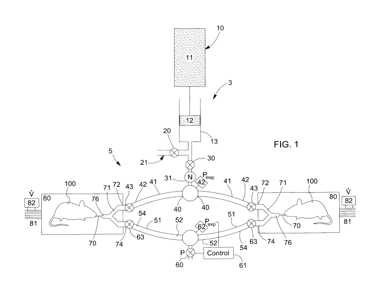
Now referring to figure 1, there is shown a mechanical ventilator system 5,
wherein
at least two subjects 100 are disposed in parallel. A single flow source 3 is
provided
to apply mechanical ventilation to the subjects. In one embodiment, the flow
source
3 provides gas to the subjects, but a person skilled in the art would
understand that
the flow source can be provided by ambient air. At least two symmetrical
inspiratory
conduits 41 having the same mechanical properties are connected to the flow
source
3. The inspiratory conduits 41 have each a first end 40 and a second end 42.
The
first ends 40 are connected to the flow source 3 in order for the gas to be
delivered
into the inspiratory conduits 41. The first ends 40 are connected to a common
suitable pressure transducer 44 in order to measure the pressure within the
conduits
41 (Pins,). The second ends 42 of the inspiratory conduits 41 are each
connected to
a Y-conduit 71. In one embodiment, individual inspiratory valve 43 is
connected to
each of the inspiratory conduit 41 to individually control inspiratory flow
for each
subject. The individual inspiratory valves 43 are moveable between a closed
and an
opened position allowing equal tidal volume to be delivered to the subjects if
such
characteristic is desired.
The mechanical ventilator 5 also contains at least two Y-conduits 71, one for
each
subject. These Y conduits deliver the gas from the inspiratory conduits 41 to
the
subjects 100. In addition, these Y-conduits allow the exhaled gas to be
directed to
different conduits than the inhaled gas conduits allowing a control of the
exhaled gas
pressure. Each Y-conduit 71 has a first end 72, a second end 74 and a stem 76.
The
first ends 72 are each connected to the second end 42 of the inspiratory
conduit 41.
The second ends 74 of the Y-conduits 71 are each connected to an expiratory
conduit 51, and the stems 76 are each connected to the subject 100 through an
intubation or tracheotomy cannula 70. The cannulae 70 are located close to the
subject's airway opening to minimize ventilator deadspace.
AMENDED SHEET
CA 02779311 2012-04-30
WO 2011/054105 PCT/CA2010/001783
14
The mechanical ventilator 5 also contains at least two expiratory conduits 51;
one
expiratory conduit for each subject. The expiratory conduits 51 are optionally
symmetrical, and can have the same mechanical properties.. Each expiratory
conduit 51 has a first end 52 and a second end 54. The second ends 54 are each
connected to the second end 74 of the Y-conduits allowing the exhaled gas from
the
subjects to be directed into the exhaled conduits 51. The first ends 52 of the
expiratory conduits 51 are connected to a common proportional valve 60. A
servo-
controller 61 is connected to the proportional valve 60 maintaining a constant
positive end-expiratory pressure (PEEP) throughout the expiratory phase based
on
measurement of the pressure in the expiratory conduits 51 (Pexp) obtained from
a
pressure transducer 62 connected to the expiratory conduits 51. Each
expiratory
conduit 51 contains an individual expiratory valve 63 connected thereto. The
expiratory valves 63 avoid a shunt pathway between the airway openings of the
individual subjects during the inspiratory phase.
Each subject 100 occupies one subject site for monitoring chest wall
displacement.
The mechanical ventilator 5 can be modified in order to assess lung function
of
multiple subjects requiring one flow source. The subjects are disposed in
parallel
and are connected to symmetrical inspiratory and expiratory conduits as
described
above. In order to assess lung function, few elements of the mechanical
ventilator 5
are modified. The flow source 3 supplies gas to the system 5, according to the
technique the operator intends to use such as FOT manoeuvres. In one
embodiment, the flow source comprises an air intake 21 controlled by an intake
valve 20. Upon activating the valve 20, a cylinder 13 connected to the air
intake 21,
is refilled with fresh gas. A computer-controlled piston pump 10, consisting
of a linear
actuator 11 drives a piston 12 into the cylinder 13. The flow source also
contains a
central inspiratory valve 30 controlling the gas entry into the system 5 upon
compressing the gas into the cylinder 13. The parameters (predetermined flow,
volume or pressure waveform, single frequency or a broader mix of frequencies)
of
CA 02779311 2012-04-30
WO 2011/054105 PCT/CA2010/001783
the gas to be injected into the system 5 depend on the techniques that the
operator
intends to use. A person skilled in the art would know these parameters and
would
also appreciate that any other known controllable flow source is suitable to
achieve
the same purpose.
5
Chest wall displacement is measured for each subject 100 at a corresponding
subject site when assessing lung functions. In a preferred embodiment, each
subject
100 is placed inside an individual body plethysmograph 80. To acquire
individual
flow data, each body plethysmograph 80 is connected to a flow sensor 81 and a
10 differential pressure transducer 82. In one embodiment, the flow sensor 81
is a
pneumotachograph. The body plethysmograph volume and the pneumotachograph
resistance are selected to ensure a flat frequency response to sufficiently
high
frequencies so that the measured flow in and out of the body plethysmograph
(V)
provides a valid and accurate estimate chest wall displacement.
In one embodiment, a nebulizer 31 is connected to the flow source to enrich
the gas
with an aerosol prior to be injected into the inspiratory conduits. Any
suitable
aerosols can be used such as methacholine, histamine, saline, carbachol and
achethylcholine.
Providing mechanical ventilation to the subjects is performed as follows. A
gas is first
supplied from the flow source and provided to the subjects disposed in
parallel. The
gas flows into the symmetrical inspiratory conduits connecting the subjects to
the
flow source. The inspiratory conduits 41 being symmetric, the differences
between
the individual inspiratory flow pathways are negligible and the relative tidal
volumes
delivered to the individual subjects depend solely on their relative lung
mechanics. If
all subjects have identical lung mechanics, they will receive identical tidal
volumes.
However, if half of the subjects have lungs twice as stiff as the other half,
they will
receive only half the tidal volume. In such inhomogeneous circumstances, an
CA 02779311 2012-04-30
WO 2011/054105 PCT/CA2010/001783
16
intelligent computer controlling the individual inspiratory valves 43 can be
used to
shorten the inspiration for more compliant subjects, permitting equal tidal
volumes to
be delivered to an inhomogeneous group of subjects.
At the end of the inspiratory cycle, the gas is then exhaled from the subjects
100,
flows into the cannulae 70, the stems 76 of the Y-conduits 71 and the second
ends
74 of the Y-conduits and to the expiratory conduits 51. The proportional valve
60
opens as necessary to bring the pressure in the expiratory conduits 51 to the
desired
PEEP level, and then modulates its degree of opening to maintain the PEEP
level
throughout the expiration phase. In one embodiment, the intake valve 20 then
opens
and the piston 12 retracts to refill the cylinder 13 with fresh gas and
prepare the next
inspiratory phase in order to repeat the cycle for a period of time desired.
In one
embodiment, inspiratory valves 43 connected to the inspiratory conduits 41 are
closed at the end of the inspiratory cycle or the inspiratory valves 43 are
adjusted in
order to provide equal tidal volume to be delivered to the subjects.
Measuring lung function requires knowledge of the pressure drop across the
respiratory system of each subject. In preparation for such measurements, a
dynamic calibration manoeuvre is performed at the onset of any given
experiment, to
individually characterize each inspiratory pathway, including the cannulae 70.
During
the calibration manoeuvre, the system is assembled with the chambers 80
closed,
except the subjects 100 are not connected to the cannulae 70. The individual
expiratory valves 63 are closed throughout the calibration manoeuvre in order
for the
system dynamics to be modelled according to the electrical equivalent circuit
shown
in Figure 2(a). Provided that the pneumotachograph resistance is negligible
compared to the resistance of the inspiratory pathway defined by the
inspiratory
conduits 41 and cannulae 70, the calibration impedance of any given pathway k
(Z(;al,k, 90) from Pinsp and the calibration flow obtained from the
corresponding
plethysmograph (Vcalk)can be calculated according to the following formula:
PCT/CA2010/001783
CA 02779311 2012-04-30 17 February 2012 17-02-2012
17
ca6c - Pingp
For any further recordings obtained with the subjects 100 connected to the
cannulae
70 throughout the remainder of the experiment, the system dynamics can be
modelled according to Figure 2(b), and the transfer impedance of the
respiratory
system of subject k (Z,r,k) can be calculated according to the following
formula:
+Zak=PIMP
k
which is easily rearranged to
Zck P kP -k
Depending on the application, parametric models of respiratory mechanics can
also
be used to represent these data in a more condensed format.
Once the calibration impedances are measured lung function assessment may be
carried out during mechanical ventilation. In this case, the steps associated
with the
method for assessment of lung function are carried out except that the
measurement
manoeuvre step is replaced with a series of steps to record and segment
pressure
and flow data obtained during mechanical ventilation.
Although Figure I shows only two parallel subjects, the concept described
above is
easily extended to more parallel subjects without departing from the scope of
the
present invention.
The mechanical ventilator and the ' lung function system of the present
invention
provides simultaneous mechanical ventilation and simultaneous measurement of
lung function of many subjects. Assessing lung function and providing
mechanical
AMENDED SHEET
CA 02779311 2012-04-30
WO 2011/054105 PCT/CA2010/001783
18
ventilation to many subjects simultaneously allow researchers to study a
greater
numbers of subjects in a shorter period of time. In addition, many subjects
can be
studied at the same time preventing physiological daily cycle variability of
the
subjects and variability from different systems. Therefore, the system of the
present
invention allows a more accurate comparison between the results obtained from
the
different subjects studied.
Examples
Preliminary validation experiments were carried out using a group of four
naive A/J
mice. In a first set of measurements, respiratory mechanics of individual mice
in
response to inhaled methacholine (MCh) challenge were captured simultaneously
by
transfer impedance according to the system of the present invention (=) and
input
impedance obtained from conventional FOT (.) as shown in Figure 3. Both
techniques produced virtually identical results.
In a second set of measurements, the MCh dose response of eight naive A/J mice
was measured using the system of the present invention with two parallel
measurement sites, i.e. by measuring consecutive sets of two parallel mice,
where
mechanical ventilation, forced oscillation waveforms and aerosol were all
provided
by a single device for each set of two animals. The data from these animals
were
grouped by the measurement site on which a subject was placed during
recording,
resulting in four animals per group. As shown in Figure 4, both groups showed
no
significant differences from each other, and the results were comparable to
those
obtained in individual animals (Figure 3). Complete transfer impedances
obtained
from the baseline recordings of each group are shown in Figure 5.
All subjects appeared adequately ventilated throughout their stay on the
device, and
no animal showed any signs of discoloration of mucosal membranes or other
indications of insufficient gas exchange. The variability between subjects and
groups
PCT/CA2010/001783
CA 02779311 2012-04-30 17 February 2012 17-02-2012
19
is comparable to the normal physiological variability that is commonly
observed in
lung function studies. These data show that both mechanical ventilation and
nebulized aerosol challenges were adequately distributed to parallel subjects.
In summary, these data demonstrate that the system of the invention permits
efficient and accurate mechanical ventilation, aerosol administration and
measurement of lung function by means of measuring transfer impedance in
parallel
subjects with a single gas supply system such as a piston pump and aerosol
generator.
Although preferred embodiments of the present invention have been described in
detailed herein and illustrated in the accompanying drawings, it is to be
understood
that the invention is not limited to these precise embodiments and that
various
changes and modifications may be effected therein without departing from the
scope
of the present invention.
AMENDED SHEET