Note: Descriptions are shown in the official language in which they were submitted.
CA 02779455 2012-04-30
WO 2011/053772 PCT/US2010/054684
METHOD AND APPARATUS FOR NON-INVASIVE TREATMENT
OF HYPERTENSION THROUGH ULTRASOUND RENAL DENERVATION
CROSS-REFERENCE TO RELATED APPLICATIONS
[0001] This application claims the benefit of the filing date
of US Provisional Patent Application No. 61/256,455, filed
October 30, 2009, entitled "METHOD AND APPARATUS FOR
NON-INVASIVE TREATMENT OF HYPERTENSION THROUGH ULTRASOUND RENAL
DENERVATION," which is incorporated by reference herein in its
entirety. The entire disclosures of US Provisional Patent
Application Nos. 61/256,429, filed on October 30, 2009, entitled
"METHOD AND APPARATUS FOR TREATMENT OF HYPERTENSION THROUGH
ULTRASOUND RENAL DENERVATION," and 61/292,618, filed on
January 6, 2010, entitled "METHOD AND APPARATUS FOR TREATMENT OF
HYPERTENSION THROUGH ULTRASOUND RENAL DENERVATION," are
incorporated by reference herein. The entire disclosure of the
International Application under the Patent Cooperation Treaty
naming Reinhard Warnking as inventor, filed of even date
herewith entitled "METHOD AND APPARATUS FOR PERCUTANEOUS
TREATMENT OF HYPERTENSION THROUGH RENAL DENERVATION" is also
incorporated by reference herein in its entirety.
TECHNICAL FIELD
[0002] The present invention relates to methods and apparatus
for inactivation of nerve conduction.
BACKGROUND OF THE INVENTION
[0003] Inactivation of specific nerves associated with a
disorder may help treat the disorder. For example, inactivation
of renal nerve conduction can be used to treat hypertension.
Successful treatment of hypertension is important for many
reasons. For example, successful treatment of hypertension has
significant clinical benefits in preventing or limiting
1
CA 02779455 2012-04-30
WO 2011/053772 PCT/US2010/054684
conditions caused by or exacerbated by hypertension; such as,
renal disease, arrhythmias, and congestive heart failure, to
name a few. While drug therapy can be used to treat
hypertension, it is not always successful. Some people are
resistant to drug therapy treatment or experience significant
side effects from drug therapy treatment.
[0004] Hypertension can be treated by inactivating conduction
of the renal nerves surrounding the renal artery. Sympathetic
renal nerve activity plays a significant role in the initiation
and maintenance of hypertension. When the brain perceives
increased renal nerve activity, signaling low blood volume or a
drop in blood pressure, it compensates by increasing sympathetic
nerve activity to the heart, the liver, and the kidneys, which
results in increased cardiac output; insulin resistance; and
most importantly, increased renin production by the kidneys.
Renin stimulates the production of angiotension, which causes
blood vessels to constrict, resulting in increased blood
pressure; and stimulates the secretion of aldosterone.
Aldosterone causes the kidneys to increase the reabsorption of
sodium and water into the blood, increasing blood volume thereby
further increasing blood pressure.
[0005] It has been established for years that surgically
cutting renal nerves results in a decrease in blood pressure and
water retention to normal levels, thereby allowing the patients'
heart, liver, and kidneys to also return to healthier
functioning. It has also been shown that a disruption of the
renal nerves has no serious ill effects. However, surgically
cutting the renal nerves requires a major surgical procedure.
It would be desirable to produce the same result without
requiring major surgery.
2
CA 02779455 2012-04-30
WO 2011/053772 PCT/US2010/054684
[0006] In order to explain the difficulties associated with
accomplishing this task without causing other damage, the
anatomy of the renal arteries and nerves will be described now.
Shown in FIG. 1 is an illustration of the renal nerves 8 that
surround the renal artery 10, which is connected to the
kidney 6. The sympathetic renal nerves 8 include both the
afferent sensory renal nerves from the kidney 6 to the brain and
the efferent sympathetic renal nerves from the brain to the
kidney 6. In addition, FIG. 2 shows a cross-section of a renal
artery 10. The renal artery wall includes layers: the intima 3,
which includes an inner single layer of endothelial cells; the
media 5, which is in the center of the artery wall; and the
adventitia 4, which is the outside layer. Also shown are the
renal nerves 8 that lie within the aventitia 4, on the surface
of the renal artery 10, and adjacent to the renal artery 10. As
can be seen from these two figures, the renal nerves 8 surround
the renal artery 10. Different individuals have the renal
nerves 8 in different locations around the renal artery. Thus,
the renal nerves may be at different radial distances from the
central axis of the renal artery, and also may be at different
locations around the circumference of the renal artery. It is
not practical to locate the renal nerves by referring to
anatomical landmarks. Moreover, it is difficult or impossible
to locate individual renal nerves using common imaging
technology.
[0007] The inability to locate and target the renal nerves 8
makes it difficult to disconnect the sympathetic renal activity
using non-surgical techniques without causing damage to the
renal artery 10 or causing other side effects. For example,
attempts to apply energy to the renal nerves can cause effects
3
CA 02779455 2012-04-30
WO 2011/053772 PCT/US2010/054684
such as stenosis, intimal hyperplasia, and necrosis. Other side
effects can include thrombosis, platelet aggregation, fibrin
clots and vasoconstriction. In addition, the inability to
target and locate the renal nerves 8 makes it difficult to
ensure that sympathetic renal nerve activity has been disrupted
sufficiently to achieve an acceptable therapeutic treatment.
[0008] US Patent No. 7,617,005 suggests the use of a radio
frequency ("RF") emitter connected to a catheter, which is
inserted in the renal artery. The RF emitter is placed against
the intima and the RF energy is emitted to heat the renal nerves
to a temperature that reduces the activity of renal nerves which
happen to lie in the immediate vicinity of the emitter. In
order to treat all the renal nerves surrounding the renal
arteries, the RF emitter source must be repositioned around the
inside of each renal artery multiple times. The emitter may
miss some of the renal nerves, leading to an incomplete
treatment. Moreover, the RF energy source must contact the
intima to be able to heat the renal nerves, which may cause
damage or necrosis to the single layer endothelium and the
intima, potentially causing intimal hyperplasia, renal artery
stenosis, and renal artery dissection.
[0009] The '005 patent also suggests the use of high-
intensity focused ultrasound to deactivate the renal nerves.
The described high-intensity focused ultrasound energy source
assertedly emits ultrasound energy in a 360 pattern around the
axis of the renal artery, and does not need to contact the
intima 3. However, the high-intensity focused ultrasound source
applies concentrated energy in a thin focal ring surrounding the
artery. It is difficult or impossible to align this thin ring
with the renal nerves because the renal nerves cannot be
4
CA 02779455 2012-04-30
WO 2011/053772 PCT/US2010/054684
visualized and targeted with current technology, and because the
renal nerves may lie at different radial distances from the
central axis of the renal artery. The latter problem is
aggravated in patients who have renal arteries with large
variations in shape or thickness. Moreover, the thin focal ring
can encompass only a small segment of each renal nerve along the
lengthwise direction of the nerves and artery. Since nerves tend
to re-grow, a small treatment zone allows the nerves to
reconnect in a shorter period of time.
[0010] For many years ultrasound has been used to enhance
cell repair, stimulate the growth of bone cells, enhance
delivery of drugs to specific tissues, and to image tissue
within the body. In addition, high-intensity focused ultrasound
has been used to heat and ablate tumors and tissue within the
body. In high-intensity focused ultrasound, an ultrasonic
transducer and associated elements are designed to bring emitted
ultrasound waves to a very sharp focus within the body,
approximating a theoretical point or line. Thus, the ultrasonic
energy applied by the transducer is dissipated within a very
small heating volume within the body, on the order of a few mm3.
This provides rapid heating of the tissues within such volume to
temperatures required for rapid necrosis, typically on the order
of 65 C or more. In some applications, high-intensity focused
ultrasound can produce tissue necrosis at a desired point or
line without adversely affecting surrounding tissue and
intervening structures that the ultrasound energy must pass
through. As mentioned above, it is difficult or impossible to
use high intensity focused ultrasound to inactive renal nerves
because the renal nerves cannot be located using practical
CA 02779455 2012-04-30
WO 2011/053772 PCT/US2010/054684
non-surgical techniques. This makes it impractical to align the
small heating volume with the renal nerves.
SUMMARY OF THE INVENTION
[0011] One aspect of the present invention provides methods
for inactivating nerve conduction in a treatment region of a
mammalian subject. The method according to this aspect of the
present invention desirably includes the step of coupling a
therapeutic ultrasound transducer with the body of the subject
remote from the treatment region, preferably at the skin of the
subject overlying the treatment region. The method preferably
further includes the step of actuating the therapeutic
ultrasound transducer to transmit therapeutically effective
softly focused ultrasound energy into an impact volume of at
least about 1.0 cm3. The impact volume desirably encompasses the
treatment region of the subject. Most preferably, the
therapeutically effective softly focused ultrasound energy is
applied throughout the impact volume at a level sufficient to
inactivate conduction of nerves, but insufficient to cause
tissue necrosis during the time required to inactivate the
nerves.
[0012] As discussed further below, the impact volume of the
softly focused therapeutic ultrasound is many times larger than
the focal region used in high intensity focused ultrasound.
Because the ultrasonic power is applied throughout the
relatively large impact volume at a level appropriate for nerve
inactivation, preferred methods according to this aspect of the
invention can be performed without locating or targeting
individual nerves. All that is required to assure that the
nerves in a treatment region of the body are inactivated is to
align the impact volume so that it encompasses the treatment
6
CA 02779455 2012-04-30
WO 2011/053772 PCT/US2010/054684
region. For example, in treatment of hypertension, the impact
volume can be aligned to encompass the renal artery over a
portion of its length, without any need to locate or target
individual renal nerves. This can be accomplished readily using
ultrasonic or other imaging techniques as discussed below.
[0013] A further aspect of the invention provides apparatus
for inactivating nerve conduction in a treatment region of a
mammalian subject. Apparatus according to this aspect of the
present invention desirably includes a therapeutic ultrasound
transducer adapted to engage with the body of the subject
outside of the treatment region as, for example, on the skin of
the subject. The apparatus desirably includes an actuator
adapted to actuate the therapeutic ultrasound transducer to
transmit therapeutically effective softly focused ultrasound
energy into an impact volume of at least about 1.0 cm3, wherein
the impact volume encompasses the treatment region of the
subject and the therapeutically effective softly focused
ultrasound energy is at an intensity sufficient to inactivate
conduction of nerves throughout the impact volume.
BRIEF DESCRIPTION OF THE DRAWINGS
[0014] FIG. 1 is an anatomical illustration of a renal artery
and renal nerves associated with it.
[0015] FIG. 2 is a cross-sectional view of a renal artery and
renal nerves associated with it.
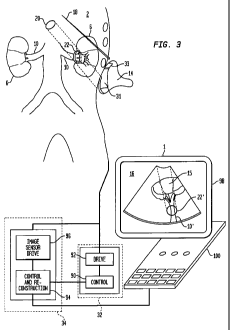
[0016] FIG. 3 is a diagrammatic view depicting apparatus of
the according to one embodiment of the present invention engaged
with a subject.
[0017] FIGS. 4A, 4B, and 4C are diagrammatic view of three
different ultrasound transducer assemblies and related elements
used in embodiments of the present invention.
7
CA 02779455 2012-04-30
WO 2011/053772 PCT/US2010/054684
[0018] FIGS. 5A, 5B, and 5C are diagrammatic views of three
different transducers and associated ultrasonic emissions from
such transducers.
[0019] FIG. 6 is a flowchart of a method according to one
embodiment of the present invention.
[0020] FIG. 7 is a flowchart of a method according to a
further embodiment of the present invention.
DETAILED DESCRIPTION
[0021] Apparatus and methods according to certain embodiments
of the present invention can be used to non-invasively
inactivate nerve conduction. For example, the apparatus and
methods can be used to inactivate conduction of all the renal
nerves 8 that surround the renal artery 10. This includes renal
nerves 8 which are located in, on the surface of, and adjacent
to the renal artery 10. Such inactivation can be achieved
without surgery and thus without typical risks, such as
thrombosis, infection, and other collateral damage.
[0022] Apparatus 1 according to one embodiment of the present
invention (FIG. 3) includes an ultrasound transducer assembly 14
and an ultrasound system 32, also referred to herein as an
actuator. The actuator 32 incorporates a control computer 90
linked to a driver 92 adapted to generate electrical signals at
the desired ultrasonic frequency as commanded by the control
computer 92. The ultrasound transducer assembly 14 in this
embodiment includes a therapeutic ultrasound transducer 31 and
an imaging transducer 33 mechanically connected to the
therapeutic transducer. In the particular embodiment of FIG. 3,
the imaging transducer lies at a fixed position and orientation
relative to the therapeutic transducer, and the therapeutic
transducer has a fixed focal length. Although these transducers
8
CA 02779455 2012-04-30
WO 2011/053772 PCT/US2010/054684
are depicted as separate elements, they may be integrated as
discussed below. In the particular procedure depicted in
FIG. 3, the transducer assembly is located extra-corporeally to
the subject 2 and engages with the skin of the subject 2. This
is typically performed using a coupling gel on the skin of the
subject 2.
[0023] The imaging transducer 33 forms a part of an imaging
unit or "imager." The imager further includes an imaging
subsystem 34 which incorporates a control and reconstruction
computer 94 linked to an image transducer driver and sensor 96,
which in turn is linked to the imaging transducer 33. Driver
and sensor 96 is arranged to actuate the imaging transducer to
emit ultrasonic imaging signals, to receive electrical signals
generated by the imaging transducer responsive to ultrasonic
echoes reflected by the subject, and to transfer the information
in the electrical signals to the control and reconstruction
computer 94. The control and reconstruction computer 94 is
arranged to control the driver and sensor unit and to
reconstruct an image of the subject's tissues from the
electrical signals received through driver and sensor 96. The
control and reconstruction computer 94 is linked to a display
98, as well as to the control computer 90 of the actuator.
Control computer 92 of the actuator and control and
reconstruction computer 96 of the imager are linked to user
input controls 100 for receipt of user commands. Although
elements 90-96 are shown as separate functional elements, these
can be integrated with one another. The algorithms required for
control of an imaging transducer and reconstruction of an image
are well-known in the art.
9
CA 02779455 2012-04-30
WO 2011/053772 PCT/US2010/054684
[0024] The aperture of the therapeutic transducer 31 is
selected to be large enough to avoid skin burn. As further
discussed below, the therapeutic transducer supplies ultrasonic
emissions having sufficient total power to heat tissues within
an impact volume 22 inside the patient's body. Transmission of
ultrasound through the skin typically results in some
dissipation of energy within the skin, and thus heating of the
skin. This limits the power which can be transmitted through a
given area of the skin without causing burns. Therefore, it is
normally necessary to apply the therapeutic ultrasound over an
area of the skin larger than the cross-sectional area of the
impact volume in a plane perpendicular to the direction of
propagation of the ultrasonic energy. The size of the emitting
aperture of the therapeutic transducer controls the area of the
skin used to transmit the ultrasonic energy into the body.
[0025] When inactivating renal nerve conduction, the
ultrasound transducer assembly 14 is preferably positioned on
the back of the subject 2 near the kidney 6 to provide a
relatively large coupling window with little intervening tissue
and, typically, no intervening bones or other obstacles which
are highly reflective to ultrasound. The large coupling window
will further permit a large aperture therapeutic transducer 31
to be utilized. In the preferred embodiment, the typical size
of the aperture is about 20 cm2, however this size will change
depending on the treatment region and the particular body
structure of the subject 2.
[0026] In a method according to one embodiment of the present
invention, the computer 94 and driver 96 actuate imaging
transducer 33 to transmit an ultrasound imaging signal 18, which
is reflected off structures of the subject 2 to produce echoes.
CA 02779455 2012-04-30
WO 2011/053772 PCT/US2010/054684
The echoes are received by the imaging transducer 33 and
converted to electrical signals, which in turn are used by
computer 94 to generate an image 16 of a body region on
display 98 that may be viewed by a user. In a preferred
embodiment, the image 16 includes a graphic overlay 15, which
shows the anticipated energy path of the therapeutic ultrasound
energy and the location of the impact volume 22 where the
ultrasonic energy emitted by the therapeutic transducer
converges to the intensity required for nerve deactivation.
Because the therapeutic transducer 31 has a fixed focal length
and is in a fixed spatial relationship with the imaging
transducer 33, the locations of the path and impact volume in
the frame of reference of the imaging transducer and image 16
are known, so that the overlay can be displayed.
[0027] A user preferably looks at the graphic overlay 15 to
adjust the ultrasound transducer assembly 14 so that the
depiction 22' of the impact volume encompasses the image 10' of
treatment region 10 (shown as the renal artery) and the energy
path is not obstructed by bone or air. Once the impact
volume 22 encompasses the treatment region 10, the user
instructs control computer 90 to actuate therapeutic
transducer 31, whereupon the therapeutic transducer emits the
therapeutically effective softly focused ultrasound energy 20 to
the impact volume 22. The therapeutic energy 20 brings the
impact volume to a temperature as discussed below and thus
inactivates conduction of all the nerves in the impact
volume 22. It is not necessary to image or locate individual
nerves.
[0028] FIG. 4A depicts the ultrasound transducer assembly 14
of FIG. 3, including imaging transducer 33 and therapeutic
11
CA 02779455 2012-04-30
WO 2011/053772 PCT/US2010/054684
transducer 31. The diagnostic imaging transducer 33 is
connected to the imaging subsystem 34, while the therapeutic
sub-assembly 31 is connected to actuator 32. The imaging
transducer 33 emits and receives imaging ultrasound 18 and
imaging subsystem 34 produces the image, whereas the therapeutic
transducer 31 transmits therapeutically effective softly focused
ultrasound energy 20 to the treatment region. In this
embodiment, the therapeutic transducer 31 is mechanically fixed
by a fixed link 36 to the imaging transducer 33 at an angle that
allows the impact volume of the therapeutic ultrasound energy to
be located within the imaged body region.
[0029] Referring to FIG. 4B, another embodiment of the
ultrasound transducer assembly 14 also includes an imaging
transducer 33, which emits imaging ultrasound 18, and
therapeutic transducer 31. However, the mechanical connection
38 between the two transducers is not fixed. The mechanical
connection 38 includes a position sensor 39, which transmits
information about the position of the therapeutic transducer 31
relative to the imaging transducer 33 to the imaging
subsystem 34 (FIG. 3). The control and reconstruction computer
uses such position information to transform the position of the
therapeutic transducer 31 into the frame of reference of the
imaging transducer, or vice-versa, so that the overlay of the
impact volume and path can be accurately displayed on the
image 16 of the subject's body. Techniques for mathematical
transformation of images between frames of reference are
well-known in the art.
[0030] Referring to FIG. 4C, the ultrasound transducer
assembly 14 may also be a phased array transducer 35 or
similarly an annular array transducer (not shown) Both of
12
CA 02779455 2012-04-30
WO 2011/053772 PCT/US2010/054684
these transducers have separate transducer elements that may be
activated separately, as known to one skilled in the art. In
one embodiment, the phased array transducer 35 performs both the
imaging, using imaging ultrasound 18, and the transmission of
the therapeutically effective softly focused ultrasound
energy 20. The phased array is connected to a system 37 which
incorporates the elements of imager subsystem 34 and actuator 32
(FIG. 3). This combined system 37 is arranged to both generate
the image 16 using transducer 35 and to control the plurality of
transducer elements 40 of the ultrasound transducer array 35, to
generate the therapeutically effective softly focused ultrasound
energy 20. When generating the image 16, the computer of system
37 causes at least one and up to several hundred transducer
elements 40 to receive the reflected echoes. This embodiment
advantageously reduces the risk of incorrectly identifying the
position of the treatment region 10 because diagnostic as well
as therapeutic pathways of the ultrasound energy 20 are
identical.
[0031] Typically, the transducer assembly 14 is provided as a
replaceable unit which can be mated with a reusable device
including the actuator 32 and imaging subsystem 34 (FIG. 3).
The transducer assembly desirably includes a data carrying
element such as a bar code, electronic memory or the like, and
the reusable device is equipped to read the data on such element
and convey the same to the computers of the actuator and imaging
subsystem. The data carried on the transducer assembly includes
parameters of the transducers, such as the proper operating
frequency for the therapeutic and imaging transducers, the focal
length of the therapeutic transducer and the size and shape of
the emitting aperture of the therapeutic transducer.
13
CA 02779455 2012-04-30
WO 2011/053772 PCT/US2010/054684
Alternatively, the data carried on the transducer assembly may
include identifying information such as a serial number which
can be used by the computers of the actuator and imaging
subsystem to retrieve information pertaining to the particular
transducer assembly from a central database accessible through a
communications link such as the internet.
[0032] A deformable coupling medium 30 (FIGS. 4A-4C) may be
provided between the therapeutic transducer 31 or 35 and the
subject. The deformable coupling may include a material that
allows the therapeutic ultrasound energy 20 to be transmitted
through it. For example, the deformable coupling medium may
include a flexible or elastic bag filled with water or a gel.
By applying a force on the ultrasound transducer to compress or
decompress the deformable medium, the location of the impact
volume 22 of the therapeutically effective softly focused
ultrasound energy 20 may be adjusted to encompass the treatment
region 10.
[0033] In another embodiment, the therapeutic transducer may
be connected to a mechanical system arranged to move the
therapeutic transducer. The control and reconstruction computer
of the imaging subsystem may be arranged to compare the location
of the impact volume with the location of the treatment region
and to actuate the mechanical system to move the therapeutic
transducer position as required to assure that the location of
the impact volume 22 encompasses the treatment region 10. In
such a system, the user may designate the boundaries of the
treatment region in the frame of reference of the image, such as
by providing manual inputs to the computer to move a cursor
displayed on the image to the boundaries of the treatment region
14
CA 02779455 2012-04-30
WO 2011/053772 PCT/US2010/054684
and entering inputs indicating that the cursor is on the
boundary.
[0034] In other embodiments, the imager uses image
acquisition elements which are not associated with the
therapeutic transducer. Merely by way of example, imaging
modalities such as X-ray, CAT, MRI, and the like can be used.
Provided that the position of the therapeutic transducer can be
determined in the frame of reference of the imaging system, or
in another frame of reference having a known transformation to
the frame of reference of the imaging system, the location of
the impact volume and the image of the subject's body can be
brought into a common frame of reference.
[0035] In the embodiments discussed above, the therapeutic
transducer focuses the ultrasound energy 20, but only to a
degree. As used in this disclosure, the with respect to
ultrasonic energy, the term "focus" means that the intensity of
the ultrasonic energy increases in the direction of propagation
away from the emitter to a location remote from the emitter
where the intensity is at a maximum. In conventional
high-intensity focused ultrasound, the transducer is designed
and operated to focus the energy into a focal region such as a
point or line which has volume as close to zero as possible,
typically a few mm3. The ultrasonic energy has high intensity
within this small focal region, but the intensity diminishes as
sharply as possible at the boundaries of the focal region. By
contrast, in the preferred embodiments of the present invention,
the therapeutic transducer is constructed and operated so that
the focal region is intentionally blurred and the ultrasonic
energy has reasonably uniform intensity throughout a relatively
large region, referred to herein as the "impact volume"
CA 02779455 2012-04-30
WO 2011/053772 PCT/US2010/054684
surrounding the point of maximum intensity. The intensity
within the impact volume desirably is uniform enough to produce
the desired therapeutic effect throughout the impact volume. In
the preferred embodiments of the present invention, the desired
therapeutic effect is inactivation of nerve conduction without
ablation or necrosis of tissue. As discussed below, this
typically requires heating solid tissues to between about 42 C
but less than 65 C as discussed below. Thus, the intensity of
the ultrasonic energy in the impact volume should be uniform
enough to heat substantially all solid tissues within the impact
volume, other than blood and those which are in intimate contact
with a cooling medium such as blood, to 42-65 C, but no tissues
are heated to above 65 C. The impact volume preferably has a
volume of 1 cm3, but less than 5 cm3. Stated another way, the
ultrasonic energy is still focused, in that it increases in
intensity in the direction of propagation from the transducer to
the impact volume, but the focus is a soft focus. The preferred
soft focus is different from the prior art devices that use
high-intensity sharply focused ultrasound for ablating tumors
and other tissue because the impact volume of the softly focused
ultrasound is 10 to 100 times larger than the volume of focal
region in high-intensity sharply focused ultrasound. In
addition, because the ultrasound energy 20 is softly focused,
the maximum intensity of the ultrasound energy in the impact
volume is 10 to 100 times less than the maximum intensity of
high-intensity sharply focused ultrasound used in ablation of
tissue. For example, in the softly focused ultrasound, the
maximum intensity in the impact volume, which is also the
maximum intensity in the beam path, typically is about 1 Watt/cm2
or less to about 10 Watt/cm2.
16
CA 02779455 2012-04-30
WO 2011/053772 PCT/US2010/054684
[0036] As can be seen in FIGS. 4A, B, and C, the softly
focused ultrasound energy 20 is directed to the treatment
region, which in FIGS. 4A, B, and C is the renal artery 10, so
that the impact volume 22 will encompass the renal artery 10 and
the nerves within the adventitia of the renal artery and
surrounding the adventitia. In regions along the path of
propagation of the ultrasound before and beyond the impact
volume 22, the intensity of the ultrasound energy 20 is too weak
to inactivate nerve conduction or cause tissue damage. Within
the impact volume, the intensity of the ultrasound energy 20 is
therapeutically effective in that it is strong enough to
inactivate nerve conduction, but it is not strong enough to
ablate tissue or cause necrosis in the time required for nerve
inactivation. Research shows that nerve damage occurs at much
lower temperatures and much faster than tissue necrosis. See
Bunch, Jared. T et al. "Mechanisms of Phrenic Nerve Injury
During Radiofrequency Ablation at the Pulmonary Vein Orifice,
Journal of Cardiovascular Electrophysiology, Volume 16,
Issue 12, Pg. 1318-1325 (Dec. 8, 2005), incorporated by
reference herein. When applying the therapeutically effective
softly focused ultrasound energy 20 to inactivate renal nerve 8
conduction, as shown in FIG. 3 and FIG. 4, the ultrasound energy
20 is strong enough to inactivate the renal nerve 8 conduction
yet not strong enough to cause damage, such as, stenosis,
intimal hyperplasia, intimal necrosis, or other injuries that
would require intervention.
[0037] Since necrosis of tissue typically occurs at
temperatures of 65 C or higher for about 10 sec or longer while
inactivation of renal nerve conduction typically occurs when the
renal nerves are at temperatures of 42 C or higher for several
17
CA 02779455 2012-04-30
WO 2011/053772 PCT/US2010/054684
seconds or longer, the dosage of the ultrasound energy is chosen
to keep the temperature in the impact volume 11 within this
temperature range for several seconds or longer.
[0038] The therapeutic transducer is designed to operate, for
example, at a frequency of about 1 MHz to about a few tens of
MHz, and typically at about 5 MHz. To generate the therapeutic
dosage of ultrasound energy within the impact volume, the
acoustic power emitted by the transducer in the preferred
embodiments typically is about 10 to about 100 watts. The
duration of the power application typically is about 10 seconds
to about 30 seconds, but may be from about 5 seconds to about a
minute or more. The precise power level and duration to provide
the correct dosage can be determined for each treatment region
by mathematical modeling and, preferably, by preclinical testing
to evaluate actual temperatures achieved with different dosages.
Such preclinical testing is helpful due to the complexity of the
biological structure such as tissue layers and physical dynamics
such as blood flow.
[0039] Moreover, the transmission of the therapeutically
effective softly focused ultrasound energy 20 may be as a pulsed
function with a duty cycle synchronized and interlaced with the
imaging ultrasound duty cycles. The pulsed operation allows the
apparatus 1 to generate the image and the therapeutic ultrasound
in real-time without obscuring the image with the therapeutic
ultrasound.
[0040] As shown in FIG. 5A, the therapeutic transducer 31 may
be geometrically formed to provide the therapeutically effective
softly focused ultrasound energy. Rather than a partial
spherical shape, which would produce a sharply focused region,
the emitting surface 46 of the transducer is a non-spherical
18
CA 02779455 2012-04-30
WO 2011/053772 PCT/US2010/054684
shape, for example, a partial ellipsoid. The ellipsoid causes
the ultrasound energy to converge but not to a single point.
Mathematical techniques for determining the intensity
distribution resulting from a particular emitting surface shape
are well known in the art, and can be used to select the correct
shape for a soft-focus transducer. The shape and size of the
non-spherical transducer is selected to generate an impact
volume that is at least 1cm3.
[0041] In another embodiment, shown in FIG 5B, the
therapeutic transducer 31 includes a planar emitter 44 which
transmits unfocused ultrasound energy and an ultrasonic lens,
such as a Fresnel lens 42, which provides the focusing action to
form the unfocused ultrasound energy into be therapeutically
effective softly focused ultrasound energy 20. In order to
accomplish this, the configuration of the lens deviates slightly
from the conventional configuration used to provide a sharp
point focus. For example, a conventional sharp-focus lens has a
partially spherical surface or, in the case of a Fresnel lens,
concentric rings configured to simulate a spherical surface. To
provide soft-focused ultrasound, the surface of lens 42 deviates
slightly from this configuration. Here again, mathematical
techniques for ultrasonic lens design are well known. Lens 42
may be replaceable by the user, so that the user can alter the
location of the impact volume by selecting a different lens
based on the difference between the location of the graphic
overlay impact volume and the location of the treatment as
displayed on the imaging system. Each replaceable lens 42 may
have a different focal length to allow the location of the
impact volume 22 of the therapeutically effective softly focused
ultrasound energy to be adjusted to encompass the treatment
19
CA 02779455 2012-04-30
WO 2011/053772 PCT/US2010/054684
region 10. Individual lenses may bear machine-readable
information which can be read by the actuator and/or imaging
subsystem as, for example, the focal length of the lens.
[0042] Where the therapeutic ultrasound transducer includes a
phased array 35 (FIG. 5C) the actuator operates the individual
transducer elements 40 of the phased array 35 to transmit
ultrasound energy 20 in a timed sequence to provide the
therapeutically effective softly focused ultrasound energy 20.
In conventional operation to yield a sharp focus, the time
sequence is selected so that emissions from elements closer to
the focal point are delayed relative to emissions from elements
further from the focal point. Thus, the ultrasonic energy from
all of the transducer elements arrives at the focal point
exactly in phase. To provide a softly focused beam, the delay
times are varied slightly from those used to provide a sharp
focus. The actuation of the phased array may also include
actuation of different elements at different amplitudes. Here
again, mathematical techniques for determining the effect of a
given pattern of delay times and actuation amplitudes are well
known. The phased array 35 may contain hundreds of transducer
elements 40.
[0043] The pattern of actuation of the plurality of
transducer elements 40 in can be varied to move the location of
the impact volume of the therapeutic energy 20 to be adjusted to
encompass the treatment region. For example, a user may
identify a treatment region and an ultrasound energy path on the
diagnostic image of the body region, which may be displayed by
the computer systems discussed above, and the computer system
may determine the activation sequence and a transducer element
power output for each transducer element 40 based on the
CA 02779455 2012-04-30
WO 2011/053772 PCT/US2010/054684
identified treatment region and the identified ultrasound energy
path. Furthermore, the pattern of actuation may also be
adjusted based on the on the subject's body structures. In this
embodiment, certain elements 40 the acoustic power output of the
various elements is adjusted so that the ultrasound energy 20 is
lower at certain points in the energy path where structures such
as bones may be obstructing the therapeutic ultrasound energy's
path to the treatment region. This adjustment may include, for
example, reducing the power to some elements, entirely
deactivating some elements, or both.
[0044] A flowchart of a method according to one embodiment of
the present invention is shown in FIG. 6. The method of FIG. 6
uses a transducer assembly incorporating separate therapeutic
and imaging transducers. The method includes the step of
engaging the ultrasound transducer assembly with the skin of the
subject (Step 56) and controlling the therapeutic transducer,
through the actuator, to transmit therapeutically effective
ultrasound energy to the impact volume (Step 66) . The method
optionally may include numerous additional steps, which are
shown in dashed lines to indicate that they are optional. First
the user connects the ultrasound transducer assembly to the
actuator and imaging subsystem (Step 50) . The actuator and
imaging subsystem read information from the transducer assembly,
and determine the focal length and size of the aperture of the
therapeutic transducer and the proper actuation frequencies for
the imaging and the therapeutic transducers (Step 52). The
control computer determines the correct actuation amplitudes to
provide the desired dosage of the therapeutic energy based on
the aperture and the frequency (Step 54). This may be
accomplished, for example by reading dosage information from the
21
CA 02779455 2012-04-30
WO 2011/053772 PCT/US2010/054684
transducer assembly or by reading a value from a look up table
programmed during manufacture of the transducer or by
calculating the value based on the parameters read from the
transducer.
[0045] Next, the user engages the transducer assembly with
the skin of the subject (Step 56). This is typically
accomplished using a deformable coupling medium such as coupling
gel on the skin of the subject. The imager will then display an
image of a part of the subject's body with the propagation path
of the ultrasonic energy and location of the impact volume
overlaid on the image (Step 58). The user adjusts the position
of the therapeutic transducer (Step 60), while looking at the
graphic display of the image to determine if the energy path is
obstructed by bone or air (Step 62) and while looking to see
that the impact volume encompasses the treatment region
(Step 64). Where the transducer assembly includes an adjustable
coupling between the therapeutic transducer and imaging
transducer, the user may adjust the coupling in this process.
The user may continue to move the transducer assembly until a
position is found where there are no obstructions and the impact
volume encompasses the treatment region. As the user adjusts
the location of the therapeutic transducer, the deformable
coupling medium attached to the therapeutic transducer may be
compressed or decompressed. When the user determines that the
impact volume is positioned correctly, the user initiates the
transmission of the therapeutically effective softly focused
ultrasound energy (Step 66). It should be noted that there is
no need for the user to locate individual nerves in the
treatment region. Rather, the user need only align the impact
volume with the treatment region and actuate the transducer in
22
CA 02779455 2012-04-30
WO 2011/053772 PCT/US2010/054684
order to achieve inactivation of nerves within the treatment
region.
[0046] If the user cannot position the therapeutic transducer
so that there are no obstructions in the path of propagation,
the user can select a different transducer assembly with a
smaller or differently-shaped aperture (Step 68) and return to
the beginning of the process (Step 50) Where the therapeutic
transducer includes a replaceable lens, the user may change the
lens on the therapeutic sub-assembly (Step 72) . When the lens
is changed, the actuator or imaging subsystem reads information
from the lens to re-determine the focal length and recalculate
the proper settings to provide the desired dosage of therapeutic
ultrasound energy, and the rest of the process proceeds from
step 54.
[0047] A method according to an embodiment using a transducer
assembly incorporating a single phased array transducer with a
plurality of transducer elements is depicted in FIG. 7. In
FIG. 7 as well, many of the steps are optional. Here again, the
user first connects the ultrasound transducer assembly to the
actuator and imaging subsystem (Step 74). Here again, the
actuator and imaging subsystem reads the transducer information
from the transducer assembly (Step 76) . The user then engages
the transducer assembly with the skin of the subject (Step 78)
and the imaging subsystem uses elements of the phased array to
transmit an imaging ultrasound signal and receive the resulting
echoes. The imaging subsystem displays the image of the body
region to the user (Step 80) The user operates the system to
bring the impact volume to a desired location encompassing the
treatment region and provide a propagation path free of
obstructions (Step 82) . The user may physically move the phased
23
CA 02779455 2012-04-30
WO 2011/053772 PCT/US2010/054684
array to move the impact volume, or may actuate the control
computer of the actuator to select different parameters for
operation of the array, so as to move the impact volume to a
different location relative to the array. The computer system
in the actuator calculates the therapeutic parameters to be
applied to the phased array such (Step 84) . In this step, a
timing sequence and a power level is calculated for each of the
plurality of transducer elements 40 to produce the
therapeutically effective softly focused ultrasound energy at
the specified impact volume location. The user then inputs a
signal to initiate the transmission of the therapeutic
ultrasound (Step 86). In response to that signal, the computer
system controls the plurality of transducer elements (Step 88),
to transmit the softly focused ultrasound energy to the impact
volume. Here again, the therapeutic ultrasound may also be
generated in a pulsed mode synchronized and interlaced with the
diagnostic imaging sequence to allow a real time display of the
image during treatment.
[0048] Numerous other variations and combinations of the
features discussed above can be utilized without departing from
the present invention as defined by the claims. As noted above,
imaging may be accomplished using modalities other than
ultrasound imaging. Also, a separate imaging transducer may be
coupled with a phased array transducer. In this variation the
phased array transducer would be used solely for transmitting
the therapeutically effective softly focused ultrasound energy.
Transducers having emitting surfaces other than an ellipsoid,
and lenses other than Fresnel lenses can be used provide the
blurring or soft focus effect. Further, lenses can be used with
non-planar transducers.
24
CA 02779455 2012-04-30
WO 2011/053772 PCT/US2010/054684
[0049] The subject may be a human or non-human mammalian
subject.
[0050] Although the invention herein has been described with
reference to particular embodiments, it is to be understood that
these embodiments are merely illustrative of the principles and
applications of the present invention. It is therefore to be
understood that numerous modifications may be made to the
illustrative embodiments and that other arrangements may be
devised without departing from the spirit and scope of the
present invention as defined by the appended claims.