Language selection

Search

Patent 2779500 Summary

Third-party information liability

Some of the information on this Web page has been provided by external sources. The Government of Canada is not responsible for the accuracy, reliability or currency of the information supplied by external sources. Users wishing to rely upon this information should consult directly with the source of the information. Content provided by external sources is not subject to official languages, privacy and accessibility requirements.

Claims and Abstract availability

Any discrepancies in the text and image of the Claims and Abstract are due to differing posting times. Text of the Claims and Abstract are posted:

  • At the time the application is open to public inspection;
  • At the time of issue of the patent (grant).
(12) Patent Application: (11) CA 2779500
(54) English Title: IRIS RETRACTOR
(54) French Title: RETRACTEUR D'IRIS
Status: Dead
Bibliographic Data
(51) International Patent Classification (IPC):
  • A61B 17/02 (2006.01)
(72) Inventors :
  • ASSIA, EHUD (Israel)
  • ELIACHAR, ELIAHU (Israel)
  • LILACH, NIR (Israel)
(73) Owners :
  • APX OPHTHALMOLOGY LTD. (Not Available)
(71) Applicants :
  • APX OPHTHALMOLOGY LTD. (Israel)
(74) Agent: FASKEN MARTINEAU DUMOULIN LLP
(74) Associate agent:
(45) Issued:
(86) PCT Filing Date: 2010-11-02
(87) Open to Public Inspection: 2011-05-05
Examination requested: 2015-10-16
Availability of licence: N/A
(25) Language of filing: English

Patent Cooperation Treaty (PCT): Yes
(86) PCT Filing Number: PCT/US2010/055026
(87) International Publication Number: WO2011/053945
(85) National Entry: 2012-05-01

(30) Application Priority Data:
Application No. Country/Territory Date
61/257,087 United States of America 2009-11-02

Abstracts

English Abstract

An iris retractor (10, 30, 50, 150, 170, 190, 200) including a plurality of hooks (12, 32, 52, 152, 172, 192, 202) disposed or formed at a distal end of slender elements (14, 34, 54, 154, 174, 194, 204), and a proximal handle (20, 40, 60, 176, 196, 206) at a proximal end of the slender elements (14, 34, 54, 154, 174, 194, 204), the slender elements (14, 34, 54, 154, 174, 194, 204) resiliently moving between retracted and expanded positions by manipulation of the slender elements, wherein in the retracted position, the hooks (12, 32, 52, 152, 172, 192, 202) are close to one another and the slender elements (14, 34, 54, 154, 174, 194, 204) are close to one another, and wherein in the expanded position, the hooks are separate and spaced apart from each other and distal portions of the slender elements are separate and spaced apart from each other.


French Abstract

L'invention porte sur un rétracteur d'iris (10, 30, 50, 150, 170, 190, 200), qui comprend une pluralité de crochets (12, 32, 52, 152, 172, 192, 202) disposés ou formés à une extrémité distale d'éléments minces (14, 34, 54, 154, 174, 194, 204), et une poignée proximale (20, 40, 60, 176, 196, 206) à une extrémité proximale des éléments minces (14, 34, 54, 154, 174, 194, 204), les éléments minces (14, 34, 54, 154, 174, 194, 204) se déplaçant élastiquement entre des positions rétractées et étendues par manipulation des éléments minces, et, dans la position rétractée, les crochets (12, 32, 52, 152, 172, 192, 202) étant proches les un des autres et les éléments minces (14, 34, 54, 154, 174, 194, 204) étant proches les uns des autres, et, dans la position étendue, les crochets étant séparés et mutuellement espacés les uns des autres, et des parties distales des éléments minces étant séparées et mutuellement espacées les unes des autres.

Claims

Note: Claims are shown in the official language in which they were submitted.


11

CLAIMS

What is claimed is:
1. An iris retractor (10, 30, 50, 150, 170, 190, 200) characterised by:
a plurality of iris grabbing hooks (12, 32, 52, 152, 172, 192, 202) disposed
or
formed at a distal end of slender elements (14, 34, 54, 154, 174, 194, 204);
and
a proximal handle (20, 40, 60, 176, 196, 206) at a proximal end of said
slender
elements (14, 34, 54, 154, 174, 194, 204), said slender elements (14, 34, 54,
154, 174,
194, 204) resiliently moving between retracted and expanded positions by
manipulation
of said slender elements (14, 34, 54, 154, 174, 194, 204), wherein in the
retracted
position, said hooks (12, 32, 52, 152, 172, 192, 202) are close to one another
and said
slender elements (14, 34, 54, 154, 174, 194, 204) are close to one another,
and wherein in
the expanded position, said hooks (12, 32, 52, 152, 172, 192, 202) are
separate and spaced
apart from each other and distal portions of said slender elements (14, 34,
54, 154, 174,
194, 204) are separate and spaced apart from each other.

2. The iris retractor (10, 30, 170) according to claim 1, further comprising a
retaining
element (16, 36, 181) that retains said slender elements (14, 34, 174) in the
retracted
position until said slender elements (14, 34, 174) are moved to the expanded
position.
3. The iris retractor (10) according to claim 2, wherein a portion of said
retaining
element (16) is formed with a groove (19), and in the expanded position, said
handle (20)
is received in said groove (19).

4. The iris retractor (30) according to claim 2, wherein said retaining
element (36)
comprises a groove (38) formed in one of said slender elements (34) for
receiving therein
the other slender element (34).

5. The iris retractor (50) according to claim 1, wherein said slender elements
(54) are
pivotally attached to one another at a pivot (56).

6. The iris retractor (10, 30, 50, 150, 170, 190, 200) according to claim 1,
wherein
each of said hooks comprises a U-shaped hook (70) with a short distal
extension (72)
formed at a tip of said slender element (14, 34, 54, 154, 174, 194, 204).

7. The iris retractor (10, 30, 50, 150, 170, 190, 200) according to claim 1,
wherein a
tip of said slender element extends from a proximal sleeve (74).

8. The iris retractor (10, 30, 50, 150, 170, 190, 200) according to claim 1,
wherein
said hook (70) is retractable into said slender element.

9. The iris retractor (170) according to claim 1, wherein said hooks (172)
curve back
onto said slender elements (174).


12

10. The iris retractor (170) according to claim 2, wherein said retaining
element (181)
is pivotally connected to a toggle lever (1820, which is pivotally connected
at a pivot
(183) on a distal end of a handle (184), said toggle lever (182) pivotable to
move said
retaining element (181) to clamp around said slender elements (174) to retain
said slender
elements (174) in the retracted position, and said toggle lever (182) is also
pivotable to
move said retaining element (181) to release said slender elements (174) to
expand to the
expanded position.

11. The iris retractor (190) according to claim 1, wherein said handle (196)
is
sufficiently resilient to flatten into an oblong shape when squeezed.

12. The iris retractor (200) according to claim 1, wherein said handle
comprises two
scissor handles (206) spring loaded by a biasing device (208).

13. A method for retraction of an iris comprising:
providing an iris retractor (10, 30, 50, 150, 170, 190, 200) that comprises a
plurality of hooks (12, 32, 52, 152, 172, 192, 202) disposed or formed at a
distal end of
slender elements (14, 34, 54, 154, 174, 194, 204), and a proximal handle at a
proximal
end of said slender elements (14, 34, 54, 154, 174, 194, 204), said slender
elements (14,
34, 54, 154, 174, 194, 204) resiliently moving between retracted and expanded
positions
by manipulation of said slender elements (14, 34, 54, 154, 174, 194, 204),
wherein in the
retracted position, said hooks (12, 32, 52, 152, 172, 192, 202) are close to
one another and
said slender elements (14, 34, 54, 154, 174, 194, 204) are close to one
another, and
wherein in the expanded position, said hooks (12, 32, 52, 152, 172, 192, 202)
are separate
and spaced apart from each other and distal portions of said slender elements
(14, 34, 54,
154, 174, 194, 204) are separate and spaced apart from each other;
inserting said slender elements (14, 34, 54, 154, 174, 194, 204) in the
retracted
position through a small incision near a limbus of an eye;
manipulating said slender elements (14, 34, 54, 154, 174, 194, 204) to the
expanded position; and
grasping and retracting a portion of the iris with said hooks (12, 32, 52,
152, 172,
192, 202).

14. The method according to claim 13, wherein the incision for insertion of
said
slender elements (14, 34, 54, 154, 174, 194, 204) is made at a different
position than an
incision for phacoemulsification.

Description

Note: Descriptions are shown in the official language in which they were submitted.


WO 2011/053945 PCT/US2010/055026
1
IRIS RETRACTOR
FIELD OF THE INVENTION
The present invention relates generally to an iris retractor used in
ophthalmic
surgical procedures.
BACKGROUND OF THE INVENTION
There are various ophthalmic procedures that require the dilation of the
pupil. For
example, a lens with a cataract is typically removed from the eye by
phacoemulsification.
This procedure breaks up the lens typically with an ultrasonically driven
tool. The tool
has an aspiration port that aspirates the broken lens material from the
patient's ocular-
chamber. It is desirable to extend the pupil during phacoemulsification to
provide the
surgeon with a wide view of the lens. One technique for extending the pupil
includes
pulling back or retracting the iris with what is referred to as an iris
retractor, and holding
the iris at its outer edges.
SUMMARY OF THE INVENTION
The present invention seeks to provide an improved iris retractor, as is
described
more in detail hereinbelow.
There is thus provided in accordance with an embodiment of the present
invention
an iris retractor including a plurality of iris grabbing hooks disposed or
formed at a distal
end of slender elements, and a proximal handle at a proximal end of the
slender elements,
the slender elements resiliently moving between retracted and expanded
positions by
manipulation of the slender elements, wherein in the retracted position, the
hooks are
close to one another and the slender elements are close to one another, and
wherein in the
expanded position, the hooks are separate and spaced apart from each other and
distal
portions of the slender elements are separate and spaced apart from each
other.
In accordance with an embodiment of the present invention a retaining element
retains the slender elements in the retracted position until the handle is
manipulated to
move the slender elements to the expanded position.
In accordance with another embodiment of the present invention a portion of
the
retaining element is formed with a groove, and in the expanded position, the
handle is
received in the groove.
In accordance with yet another embodiment of the present invention the
retaining
element includes a groove formed in one of the slender elements for receiving
therein the
other slender element.


WO 2011/053945 PCT/US2010/055026
2
In accordance with still another embodiment of the present invention the
slender
elements are pivotally attached to one another at a pivot.
In accordance with an embodiment of the present invention a tip of the slender
element includes a U-shaped hook with a short distal extension.
In accordance with an embodiment of the present invention a tip of the slender
element extends from a proximal sleeve.
In accordance with an embodiment of the present invention the hook is
retractable
into the slender element.
There is also provided in accordance with an embodiment of the present
invention
a method for retraction of an iris including providing an iris retractor that
includes a
plurality of hooks disposed or formed at a distal end of slender elements, and
a proximal
handle at a proximal end of the slender elements, the slender elements
resiliently moving
between retracted and expanded positions by manipulation of the handle,
wherein in the
retracted position, the hooks are close to one another and the slender
elements are close to
one another, and wherein in the expanded position, the hooks are separate and
spaced
apart from each other and distal portions of the slender elements are separate
and spaced
apart from each other, inserting the slender elements in the retracted
position through a
small incision near a limbus of an eye, manipulating the handle to move the
slender
elements to the expanded position, and grasping and retracting a portion of
the iris with
the hooks.
The incision for insertion of the slender elements can be made at a different
position than an incision for phacoemulsification.
BRIEF DESCRIPTION OF THE DRAWINGS
The present invention will be understood and appreciated more fully from the
following detailed description taken in conjunction with the drawings in
which:
Figs. IA-IC are simplified perspective, top-view and side-view illustrations,
respectively, of an iris retractor, in a non-expanded orientation, constructed
and operative
in accordance with an embodiment of the present invention;
Figs. ID-IE are simplified perspective and side-view illustrations,
respectively, of
the iris retractor of Figs. IA-IC, in the non-expanded orientation placed on
an eye;
Figs. 2A-2C are simplified perspective, side-view and top-view illustrations,
respectively, of the iris retractor of Figs. IA-IC, in a partially expanded
orientation, in
accordance with an embodiment of the present invention;


WO 2011/053945 PCT/US2010/055026
3
Figs. 3A-3C are simplified perspective, side-view and top-view illustrations,
respectively, of the iris retractor of Figs. IA-1C, in a fully expanded
orientation, in
accordance with an embodiment of the present invention;
Figs. 3D-3E are simplified side-view and perspective illustrations,
respectively, of
the iris retractor of Figs. lA-1C, in the fully expanded orientation placed on
the eye;
Figs. 4A-4C are simplified perspective, side-view and top-view illustrations,
respectively, of an iris retractor, in a non-expanded orientation, constructed
and operative
in accordance with another embodiment of the present invention;
Figs. 4D-4E are simplified perspective and side-view illustrations,
respectively, of
the iris retractor of Figs. 4A-4C, in the non-expanded orientation placed on
an eye;
Figs. 5A-5C are simplified perspective, top-view and side-view illustrations,
respectively, of the iris retractor of Figs. 4A-4C, in an expanded
orientation, in
accordance with an embodiment of the present invention;
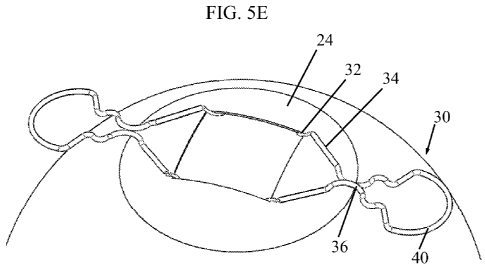
Figs. 5D-5E are simplified side-view and perspective illustrations,
respectively, of
the iris retractor of Figs. 4A-4C, in the expanded orientation placed on the
eye;
Fig. 5F is a simplified perspective illustration of a modified version of the
iris
retractor of Figs. 4A-4C, in accordance with an embodiment of the present
invention;
Figs. 6A-6C are simplified perspective, side-view and top-view illustrations,
respectively, of an iris retractor, in a non-expanded orientation, constructed
and operative
in accordance with yet another embodiment of the present invention;
Figs. 6D-6E are simplified side-view and perspective illustrations,
respectively, of
the iris retractor of Figs. 6A-6C, in the non-expanded orientation placed on
an eye;
Figs. 7A-7C are simplified perspective, top-view and side-view illustrations,
respectively, of the iris retractor of Figs. 6A-6C, in an expanded
orientation, in
accordance with an embodiment of the present invention;
Figs. 7D-7E are simplified side-view and perspective illustrations,
respectively, of
the iris retractor of Figs. 7A-7C, in the expanded orientation placed on the
eye;
Figs. 8 and 9 are simplified perspective illustrations of different tips for
the iris
retractor of any of the above embodiments, in accordance with different
embodiments of
the present invention;
Fig. 9A is a simplified perspective illustration of the iris retractor with
the distal
extension of Fig. 8 or 9 in use, in accordance with an embodiment of the
present
invention;


WO 2011/053945 PCT/US2010/055026
4
Figs. l0A-l0E are simplified perspective illustrations of a retractable tip
for the
iris retractor of any of the above embodiments, in accordance with an
embodiment of the
present invention, shown gradually from fully extended to fully retracted
positions;
Fig. 11 is a simplified pictorial illustration of an iris retractor,
constructed and
operative in accordance with another embodiment of the present invention;
Figs. 12A-12D are simplified pictorial illustrations of an iris retractor,
constructed
and operative in accordance with yet another embodiment of the present
invention;
Figs. 13A-13H are simplified pictorial illustrations of a manipulator for
operating
the iris retractor of Figs. 12A-12D, constructed and operative in accordance
with an
embodiment of the present invention;
Figs. 14A-14D are simplified pictorial illustrations of an iris retractor,
constructed
and operative in accordance with still another embodiment of the present
invention; and
Figs. 15A-15E are simplified pictorial illustrations of an iris retractor,
constructed
and operative in accordance with another embodiment of the present invention.
DETAILED DESCRIPTION OF EMBODIMENTS
Reference is now made to Figs. IA-3C, which illustrate an iris retractor 10,
constructed and operative in accordance with a non-limiting embodiment of the
present
invention.
his retractor 10 includes a plurality of iris grabbing hooks 12 (Figs. 2A-3C)
disposed or formed at a distal end of one or more slender elements 14. In the
illustrated
embodiment, there are two slender elements 14. The slender elements 14 are
arranged to
move through a retaining element 16 from a fully retracted position (Figs. IA-
IQ to a
partially expanded position (Figs. 2A-2C) to a fully expanded position (Figs.
3A-3C). A
proximal portion 18 of retaining element 16 is formed with a groove 19. The
proximal
ends of slender elements 14 terminate in a proximal handle 20. The slender
elements 14
may be joined as a single element before connection to handle 20 or may be
joined at the
handle 20. In the fully expanded position, handle 20 is pushed completely into
groove 19
and is squeezed and held in this position by the side walls of groove 19.
(Alternatively,
handle 20 may "click" into groove 19. Accordingly, there can be a fixed
configuration,
wherein handle 20 clicks into groove 19 and slender elements 14 have a fixed
expansion,
or an adjustable expansion configuration, wherein the more the slender
elements 14 are
inserted into the eye the larger is their lateral expansion.) Retaining
element 16 retains
slender elements 14 in the retracted position until handle 20 is pushed
towards groove 19.


WO 2011/053945 PCT/US2010/055026
Slender elements 14 and hooks 12 may be constructed of a metal or plastic
wire,
such as but not limited, NITINOL or stainless steel or a medically safe
plastic with
suitable resilience, e.g., a shape memory polymer plastic.
Figs. 1D-1E illustrate a pair of iris retractors 10 in a non-expanded
orientation
(i.e., retracted position) placed on an eye. A portion of retaining element 16
abuts against
the cornea 22, typically but not necessarily at the limbus 23. As seen in the
figures, iris
retractor 10 is inserted through a small incision (e.g., 1.0-1.5 mm incision)
at the limbus
23. Retaining element 16 prevents iris retractor 10 from encroaching too much
into the
cornea 22.
Pushing handle 20 towards retaining element 16 deploys slender elements 14 and
hooks 12 out of retaining element 16. As seen in Figs. 3D-3E, hooks 12 grab
and hook
onto the iris 24 and retract the iris 24 for exposing the lens 25 to provide a
good working
opening for the surgeon. Retaining element 16 anchors the retractor 10 by
applying a
counter force on the outside of the limbus 23.
Hooks 12 are separate and spaced apart from each other upon distal movement of
slender elements 14 through retaining element 16. Thus, a single iris
retractor provides
spaced apart retraction points, as opposed to some prior art iris retractors
which only work
at a single point.
The incision for insertion of the iris retractor may be made at a different
position
(e.g., perpendicular thereto) than the incision made for phacoemulsification.
This is
advantageous because in this manner the iris retractor does not get in the way
of the
surgeon.
Reference is now made to Figs. 4A-5E, which illustrate an iris retractor 30,
constructed and operative in accordance with another embodiment of the present
invention.
his retractor 30 includes a plurality of hooks 32 disposed or formed at a
distal end
of one or more slender elements 34. In the illustrated embodiment, there are
two slender
elements 34. The proximal ends of slender elements 34 terminate in a proximal
handle 40.
Handle 40 and slender elements 34 are made of a resilient, flexible material
(e.g., metal or
plastic) to form a kind of resilient tweezers or pliers. The slender elements
34 are held in
the non-expanded (retracted) orientation by a retaining element 36 (which may
be formed
as a loop) of the slender elements 34 being caught in one or more proximal
grooves 38
formed in the other slender element 34. Another option for keeping iris
retractor 30 in its


WO 2011/053945 PCT/US2010/055026
6
non-expanded state is by pressing elements 37, without slender elements 34
being caught
in grooves 38.
Figs. 4D-4E illustrate a pair of iris retractors 30 in a non-expanded
orientation
(i.e., retracted position) placed on the eye. A portion of retaining element
36 abuts against
the cornea 22, typically but not necessarily at the limbus 23.
Squeezing handle 40 releases the slender element 34 that is initially caught
in
groove 38 of retaining element 36. (For the other option mentioned above, iris
retractor
30 moves to the expanded position by releasing elements 37.) By virtue of
their
resilience, slender elements 34 spring outwards to the expanded position in
Figs. 5A-5E.
As seen in Figs. 4A-5E, the geometry of iris retractor 30 enables expansion of
hooks 32
without resulting in significant expansion in the area of retaining elements
36.
As seen in Figs. 5D-5E, hooks 32 grab and hook onto the iris 24 and retract
the
iris 24 for exposing the lens 25 to provide a good working opening for the
surgeon.
Retaining element 36 anchors the retractor 30 by applying a counter force on
the outside
of the limbus 23.
Reference is now made to Fig. 5F, which illustrates a modified version of the
iris
retractor 30, in accordance with an embodiment of the present invention. In
this
embodiment, iris retractor 30 is provided with a flexible clip 42 in handle
40. This design
allows making the retractor smaller and may provide more spring (expansion)
force.
Reference is now made to Figs. 6A-7E, which illustrate an iris retractor 50,
constructed and operative in accordance with yet another embodiment of the
present
invention.
his retractor 50 includes a plurality of hooks 52 disposed or formed at a
distal end
of one or more slender elements 54. In the illustrated embodiment, there are
two slender
elements 54, which pivot about a pivot 56. The proximal ends of slender
elements 54
terminate in a proximal handle 60. Handle 60, pivot 56 and slender elements 54
form a
kind of scissors. Iris retractor 50 is normally expanded and slender elements
54 are held
in the non-expanded (retracted) orientation by the resilience of handle 60
(thus handle 60
serves as the retaining element for initially holding the slender elements 54
in the
retracted orientation.
Figs. 6D-6E illustrate a pair of iris retractors 50 in a non-expanded
orientation
(i.e., retracted position) placed on the eye. A portion of iris retractor 50
(e.g., near the
pivot 56) abuts against the cornea 22, typically but not necessarily at the
limbus 23.


WO 2011/053945 PCT/US2010/055026
7
Manipulating handle 60 "scissors out" the slender elements 54 to the expanded
position in Figs. 7A-7E. As seen in Figs. 7D-7E, hooks 52 grab and hook onto
the iris 24
and retract the iris 24 for exposing the lens 25 to provide a good working
opening for the
surgeon. A portion of iris retractor 50 (e.g., near the pivot 56) anchors the
retractor 50 by
applying a counter force on the outside of the limbus 23.
Reference is now made to Figs. 8 and 9, which illustrate different tips for
the iris
retractor of any of the above embodiments, in accordance with different
embodiments of
the present invention. In Fig. 8, a tip 70 is shown that has a U-shaped hook
with a short
distal extension 72. In Fig. 9, the same tip 70 is shown extending from a
proximal sleeve
74. The sleeved hooks (as shown in Fig. 9) can be retracted as shown in Fig.
10.
Reference is now made to Fig. 9A, which illustrates the iris retractor with
the
distal extension 72 of Fig. 8 or 9 in use, in accordance with an embodiment of
the present
invention. It is seen that distal extension 72 firmly and positively sets the
tool against the
edges of the iris, and thus helps ensure proper, reliable and safe retraction
of the iris.
Reference is now made to Figs. l0A-10E, which illustrate a sleeved hook 80 for
the iris retractor of any of the above embodiments, in accordance with an
embodiment of
the present invention, shown gradually from fully extended to fully retracted
positions.
Sleeved hook 80 is similar to the hook shown on Fig. 9, and may or may not
have a distal
extension like the embodiment of Fig. 9. Any suitable retracting mechanism
(not shown)
may be used to retract and/or extend retractable hook 80 into and/or out of
the slender
elements.
Reference is now made to Fig. 11, which illustrates an iris retractor 150,
constructed and operative in accordance with another embodiment of the present
invention.
his retractor 150 includes a plurality of hooks 152 disposed or formed at
distal
ends of a first slender element 154. The first slender element 154 may be
adjustable in
length, such as by means of a flexible and extendable member 155 at a central
portion
thereof. A second slender element 156 (which may be arranged to move through a
guide
element, not shown, similar to that described above) is pivotally attached to
first slender
element 154. An anchor element 158 is mounted at a proximal position on the
second
slender element 156. The proximal end of second slender element 156 terminates
in a
proximal handle 160.
As seen in Fig. 11, the hooks 152 and first slender element 154 are inserted
through a small incision at the limbus 144 and are manipulated by the surgeon
so that


WO 2011/053945 PCT/US2010/055026
8
hooks 152 spread apart and retract the iris 134. Anchor element 158 anchors
the retractor
by applying a counter force on the outside of limbus 144.
Reference is now made to Figs. 12A-12D, which illustrate an iris retractor
170,
constructed and operative in accordance with another embodiment of the present
invention.
his retractor 170 includes a plurality of hooks 172 disposed or formed at a
distal
end of one or more slender elements 174. In the illustrated embodiment, there
are two
slender elements 174. The proximal ends of slender elements 174 terminate in a
proximal
handle 176. Handle 176 and slender elements 174 are made of a resilient,
flexible
material (e.g., metal or plastic) to form a kind of resilient tweezers or
pliers. The hooks
172 in this embodiment curve back onto slender elements 174 and may optionally
abut
against slender elements 174.
Fig. 12C illustrates iris retractor 170 in a non-expanded orientation inserted
through a small incision at the limbus 23. Fig. 12D illustrates iris retractor
170 in an
expanded orientation, wherein hooks 172 grab and hook onto the iris 24 and
retract the
iris 24 for exposing the lens to provide a good working opening for the
surgeon.
Reference is now made to Figs. 13A-13H, which illustrate a manipulator 180,
for
operating iris retractor 170, constructed and operative in accordance with an
embodiment
of the present invention.
Manipulator 180 includes a retaining element 181 pivotally connected to a
toggle
lever 182, which is in turn pivotally connected at a pivot 183 on a distal end
of a handle
184. The distal end of a handle 184 includes an anvil 185 formed with a hole
186 through
which retaining element 181 passes. Handle 176 of iris retractor 170 fits on a
lug 187
(e.g., pin) that protrudes from the bottom side of anvil 185. Lug 187 fits
into the center of
handle 176.
In Figs. 13A, 13B, 13E and 13F, toggle lever 182 is moved to the position
wherein
retaining element 181 is moved down to clamp around the slender elements 174
of iris
retractor 170, thus retaining slender elements 174 in the non-expanded
orientation
(retracted position). In Figs. 13C, 13D, 13G and 13H, toggle lever 182 is
moved to the
position (indicated by arrow F) wherein retaining element 181 is moved up to
release the
slender elements 174 of iris retractor 170, thus allowing slender elements 174
to expand
to the expanded orientation.


WO 2011/053945 PCT/US2010/055026
9
Reference is now made to Figs. 14A-14D, which illustrate an iris retractor
190,
constructed and operative in accordance with another embodiment of the present
invention.
his retractor 190 includes a plurality of hooks 192 disposed or formed at a
distal
end of one or more slender elements 194. In the illustrated embodiment, there
are two
slender elements 194. The proximal ends of slender elements 194 terminate in a
proximal
handle 196. Handle 196 and slender elements 194 are made of a resilient,
flexible
material (e.g., metal or plastic or shape memory) to form a kind of resilient
tweezers or
pliers. Handle 196 in this embodiment is sufficiently resilient such that it
flattens into an
oblong shape when squeezed, as seen in Fig. 14B. Handle 196 springs back to
its original
shape to move iris retractor 190 to the expanded orientation.
Fig. 14C illustrates iris retractor 190 in a non-expanded orientation inserted
through a small incision at the limbus 23. As mentioned before, handle 196
flattens into
an oblong shape. Fig. 14D illustrates iris retractor 190 in an expanded
orientation,
wherein hooks 192 grab and hook onto the iris 24 and retract the iris 24 for
exposing the
lens to provide a good working opening for the surgeon.
Reference is now made to Figs. 15A-15E, which illustrate an iris retractor
200,
constructed and operative in accordance with another embodiment of the present
invention.
his retractor 200 includes a plurality of hooks 202 disposed or formed at a
distal
end of one or more slender elements 204. In the illustrated embodiment, there
are two
slender elements 204. The proximal ends of slender elements 204 form a
proximal handle
that includes two scissor handles 206. Handles 206 are spring loaded by a
biasing device
208, such as a coil spring which has ends attached to the handles 206.
Fig. 15D illustrates iris retractor 200 in a non-expanded orientation inserted
through a small incision at the limbus 23. Handles 206 are squeezed and held
together so
that slender elements 204 are retracted together, as shown in Fig. 15B. Fig.
15E illustrates
iris retractor 200 in an expanded orientation, wherein hooks 202 grab and hook
onto the
iris 24 and retract the iris 24 for exposing the lens to provide a good
working opening for
the surgeon.
It will be appreciated by persons skilled in the art that the present
invention is not
limited by what has been particularly shown and described hereinabove. Rather
the scope
of the present invention includes both combinations and subcombinations of the
features
described hereinabove as well as modifications and variations thereof which
would occur


WO 2011/053945 PCT/US2010/055026
to a person of skill in the art upon reading the foregoing description and
which are not in
the prior art.

Representative Drawing
A single figure which represents the drawing illustrating the invention.
Administrative Status

For a clearer understanding of the status of the application/patent presented on this page, the site Disclaimer , as well as the definitions for Patent , Administrative Status , Maintenance Fee  and Payment History  should be consulted.

Administrative Status

Title Date
Forecasted Issue Date Unavailable
(86) PCT Filing Date 2010-11-02
(87) PCT Publication Date 2011-05-05
(85) National Entry 2012-05-01
Examination Requested 2015-10-16
Dead Application 2018-02-13

Abandonment History

Abandonment Date Reason Reinstatement Date
2017-02-13 R30(2) - Failure to Respond
2017-11-02 FAILURE TO PAY APPLICATION MAINTENANCE FEE

Payment History

Fee Type Anniversary Year Due Date Amount Paid Paid Date
Application Fee $400.00 2012-05-01
Registration of a document - section 124 $100.00 2012-07-24
Maintenance Fee - Application - New Act 2 2012-11-02 $100.00 2012-10-11
Maintenance Fee - Application - New Act 3 2013-11-04 $100.00 2013-10-29
Maintenance Fee - Application - New Act 4 2014-11-03 $100.00 2014-10-21
Request for Examination $800.00 2015-10-16
Maintenance Fee - Application - New Act 5 2015-11-02 $200.00 2015-10-21
Maintenance Fee - Application - New Act 6 2016-11-02 $200.00 2016-10-25
Owners on Record

Note: Records showing the ownership history in alphabetical order.

Current Owners on Record
APX OPHTHALMOLOGY LTD.
Past Owners on Record
None
Past Owners that do not appear in the "Owners on Record" listing will appear in other documentation within the application.
Documents

To view selected files, please enter reCAPTCHA code :


To view images, click a link in the Document Description column. To download the documents, select one or more checkboxes in the first column and then click the "Download Selected in PDF format (Zip Archive)" or the "Download Selected as Single PDF" button.

List of published and non-published patent-specific documents on the CPD .

If you have any difficulty accessing content, you can call the Client Service Centre at 1-866-997-1936 or send them an e-mail at CIPO Client Service Centre.


Document
Description 
Date
(yyyy-mm-dd) 
Number of pages   Size of Image (KB) 
Abstract 2012-05-01 1 70
Claims 2012-05-01 2 98
Drawings 2012-05-01 24 357
Description 2012-05-01 10 469
Representative Drawing 2012-06-27 1 11
Cover Page 2012-07-18 1 45
Claims 2016-01-06 2 60
Claims 2016-07-29 2 67
Fees 2012-10-11 1 163
Assignment 2012-09-06 4 118
PCT 2012-05-01 14 485
Assignment 2012-05-01 4 135
Correspondence 2012-05-01 1 42
Correspondence 2012-07-20 1 39
Assignment 2012-07-24 5 189
Fees 2013-10-29 1 33
Correspondence 2014-03-24 9 381
Correspondence 2014-04-11 1 17
Fees 2014-10-21 1 33
Prosecution-Amendment 2016-01-06 8 264
Request for Examination 2015-10-16 2 67
Fees 2015-10-21 1 33
Change of Agent 2015-11-23 2 73
Office Letter 2015-11-30 1 22
Office Letter 2015-11-30 1 25
Examiner Requisition 2016-02-01 4 300
Amendment 2016-07-29 7 295
Examiner Requisition 2016-08-12 4 232