Note: Descriptions are shown in the official language in which they were submitted.
PROCESS FOR PURIFYING PROCESSING FLUIDS
BACKGROUND OF THE INVENTION
FIELD OF THE INVENTION
The present invention relates to purifying processing fluids; e.g.,
solvents, chemicals, etc., used in various refinery and petrochemical
operations. More particularly, the present invention relates to a process to
maximize the recovery of a desired processing fluid from a mixture/solution of
a processing fluid and contaminants.
DESCRIPTION OF PRIOR ART
In refining, petrochemical and other industrial applications, processing
fluids are used to perform certain functions; e.g., remove acidic components
from gas streams, as solvents in extractive distillation processes, etc. In
addition, heavy components (contaminants) become entrained in the
processing fluid. In most cases, these processing liquids are expensive and/or
pose environmental disposal hazards and accordingly, must be purified or
reclaimed for further use. In addition to the use of processing fluids in
refinery/petrochemical operations, processing fluids can be used in other
environments; e.g., the well known use of glycols to prevent gas hydrate
formation in offshore oil and gas operations.
Typically, in purifying/reclaiming the processing fluids, by whatever
method, there is a waste stream which contains entrained impurities which
have been removed during the purifying/reclaiming process. As noted, many
CA 2779520 2017-08-08
of these processing fluids are quite expensive and the goal of any
purifying/reclaiming process is to ensure that, to the extent possible, all of
the
processing fluid has been recovered; i.e., there is essentially no or a de
minimus
amount present in the waste stream from the purifying/reclaiming process.
A process for purifying a processing fluid comprising providing a feed stream
comprising used process fluid, low boiling components, and contaminants. The
feed
stream is introduced into a first separation zone, wherein the feed stream is
at least
partially vaporized to produce a first vapour stream comprising substantially
contaminant-free processing fluid and low boiling components. A second stream
comprises processing fluid and contaminants and returns a first portion of the
second stream to the first separation zone, and introduces a second portion of
the
second stream to a second separation zone. There is a wiped film evaporator,
wherein the second portion of the second stream is at least partially
vaporized to
produce a third stream comprising substantially contaminant-free processing
fluid
and a fourth stream comprising contaminants removed from the feed stream. The
second portion of the second stream is 10 - 30% by volume of the feed stream
introduced into the first separation zone.
2
CA 2779520 2017-10-12
CA 02779520 2012-04-30
WO 2011/053983
PCT/US2010/055132
SUMMARY OF THE INVENTION
In one aspect, the present invention provides a closed loop process or
method for removing contaminants from a used processing fluid, so that the
processing fluid can be recycled for further usage.
In another aspect, the present invention provides a two-step method to
maximize recovery of a processing fluid from a processing fluid/contaminant
mixture or solution. In the first step, the processing fluid/contaminant
mixture
is subjected to a first separation zone, generally a vacuum flash to provide a
first stream comprising the bulk of the processing fluid freed of
contaminants;
and a second stream containing the remainder of the processing fluid and
contaminants. In the second step of the process, the second stream is
subjected to a second separation zone, preferably in a wiped film evaporator,
to produce a third stream comprising purified processing fluid and a fourth
stream comprising waste products/contaminants from the processing
fluid/contaminant mixture.
3
CA 02779520 2012-04-30
WO 2011/053983
PCT/US2010/055132
BRIEF DESCRIPTION OF THE DRAWING
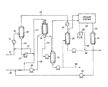
The single figure is a schematic flow sheet showing one embodiment of
the present invention.
4
CA 02779520 2012-04-30
WO 2011/053983
PCT/US2010/055132
DESCRIPTION OF PREFERRED EMBODIMENTS
While the present invention will be described with respect to the
recovery of amines such as diethanol amines used to scrub gas streams to
natural gas, to absorb components such as sulphur containing and other
gases, it will be understood, as noted above, that it is not so limited.
Accordingly, the process of the present invention can be used to reclaim
and/or purify any number of processing liquids used in any number of
processes.
As noted above, in addition to the absorbed components; e.g., the
acidic gases, the processing fluid becomes entrained with heavy, generally
non-absorbed components which, over time deleteriously affects the efficacy
of the processing fluid, causes damage to equipment, etc. One of the goals of
the present invention is to separate the generally non-absorbed, heavy
components, hereafter referred to as contaminants, impurities or waste
products from the processing fluid.
Referring then to the single figure, a contaminated stream of an alkanol
amine (processing fluid) and impurities which has been adjusted to a pH of
from about 8 to Ills fed via line 10 where it is mixed with a stream from line
13, described more fully hereafter. The combined streams pass through and
are heated in a steam heat exchanger 14, the temperature being raised to
about 250-350 F, and introduced via line 16 to a flash vessel 18. It will be
understood that flash vessel 18 can take many different forms, and is
typically
5
CA 02779520 2012-04-30
WO 2011/053983
PCT/US2010/055132
operated under vacuum, in this case provided by a vacuum system shown
schematically as 20.
As noted, the feed stream 10 is mixed with a stream from line 13, the
stream in line 13 being excess liquid from flash vessel 18, which requires
reboil. The remaining portion of the feed to vessel 18 is pumped via pump 42
and line 44 to a distillation zone; e.g., an evaporator, particularly a wiped
film
evaporator 46, to distill the processing fluid and separate it from various,
low
vapour pressure impurities/contaminants. As noted, excess liquid and low
vapour pressure impurities not sent via line 44 to evaporator 46 are
recirculated as reboil to flash vessel 18. The flash loop allows for steady
and
consistent feed rate to evaporator 46 which, as is known to one skilled in the
art, is essential to its operation. A back pressure device (not shown) is in
line
16 just prior to the stream passing through line 16 entering flash vessel 18
to
eliminate any two phase flow in the circulation of the excess liquid from
flash
vessel 18.
The high vapour pressure components that boil at preset operating
temperatures and pressures in flash vessel 18 form vapours that are drawn by
a vacuum system 20 via line 22 through condenser 24 to form a liquid which
accumulates in receiving vessel 26.
A slip stream, which constitutes typically 10 to 30%; e.g., 20%, of the
total feed stream introduced into flash vessel 18, as noted, is introduced
into
evaporator 46 via pump 42 and line 44. Distillate from evaporator 46 is
6
removed via line 52 and collects in receiving vessel 54. Alternatively, the
distillate from evaporator 46, as shown, can be discharged as a product
stream via line 55 or sent to receiving vessel 26, wherein it is mixed with
liquid
product initially flashed from flash vessel 18.
In the case of alkanol amines, the operating conditions in flash vessel
18 versus the operating condition in wiped film evaporator 46 are such that
the
temperature conditions in evaporator 46 are generally in the range of from
3000 to 400 F and under a vacuum of less than about 25mm Hg preferably
less than 10 mm. Hg, in order to effect proper distillations, whereas in the
case
of flash vessel 18, the temperature can range from about 2500 to 350 F, and
the pressure from about 30 to 500 mm Hg.
The impurities or waste from evaporator 46 are removed via line 48 and
pump 50, and discharged as waste through line 38. Typically, the amount of
impurities in the contaminated feed stream; i.e., the stream in line 10, are
relatively small and accordingly, recycling of separated impurities back to
evaporator 46 can be used.
As noted, purified processing fluid is collected in receiving vessel 26,
both from initial flash from flash vessel 18 and the distillate from
evaporator 46
and constitutes the final product which is removed via line 28.
Vacuum system 20, as noted above, provides reduced pressure (30 to
500 mm Hg) in the flash vessel 18, and a deeper vacuum (less than 25 mm
Hg, preferably less than 10 mm. Hg) in evaporator 46.
7
CA 2779520 2017-10-12
CA 02779520 2012-04-30
WO 2011/053983
PCT/US2010/055132
Any low boiling, high vapour pressure components that are not
condensed elsewhere in the system are drawn in to vacuum system 20 and
exit as a recovered component. Generally, these low boiling, high vapour
pressure components are sulphur-containing gases or similar materials, which
the processing fluid is designed to absorb. Thus, they are not a contaminant
or waste product as are the heavier components that become entrained in the
processing fluid. Accordingly, they, together with the processing fluid free
of
the entrained heavier components, can be further used. The recovered
components are compressed in compression station 29 and are introduced
into the final product stream avia lima.* This final step allows recovery of
all components, other than the undesirable impurities and waste from the
alkanol amine. This novel approach makes the process a closed loop system
(only rejecting the components considered as waste) and produces no waste
vapour (emissions) stream. Water condensate from vacuum system 20 is
directed to a receiving vessel 34 via line 32 and, as shown, can be recycled
via pump 36 into line 38 to dilute and allow better flow of the concentrated
impurities (waste) from evaporator 46.
Although specific embodiments of the invention have been described
herein in some detail, this has been done solely for the purposes of
explaining
the various aspects of the invention, and is not intended to limit the scope
of
the invention as defined in the claims which follow. Those skilled in the art
will
understand that the embodiment shown and described are exemplary, and
8
CA 02779520 2012-04-30
WO 2011/053983
PCT/US2010/055132
various other substitutions, alterations and modifications, including but not
limited to those design alternatives specifically discussed herein, may be
made in the practice of the invention without departing from its scope.
9