Note: Descriptions are shown in the official language in which they were submitted.
CA 02779525 2012-04-30
WO 2011/053328 PCT/US2009/062918
TITLE OF THE INVENTION
SYSTEM AND METHOD EMPLOYING THREE-DIMENSIONAL AND TWO-
DIMENSIONAL DIGITAL IMAGES
FIELD OF THE INVENTION
[0001] The present invention relates generally to digital images, and more
particularly, to the
viewing of digital images.
BACKGROUND OF THE INVENTION
[0002] The scanning of paper documentation into digital images is well known.
Some of the
advantages of digital or electronic documents over paper documents include
reduced storage
space, immediate and simple copying, quick retrieval, easy sharing through
electronic transfer
(e.g., e-mail), persistent and non-volatile nature of a digital format, and
the conservation of
natural resources such as trees. While a completely digital office is not a
reality for most
businesses, it is rare to find a business that doesn't rely heavily on digital
documents in the
ordinary course of its business.
[0003] For example, property owners, land developers, architects, and document
management
professionals scan active and historical documents relating to properties,
such as building
blueprints, floor plans, and riser diagrams, to save space and enable more
efficient copying and
distribution of the documents. However, once a drawing is scanned, the scale
information on the
drawing is not computer recognizable when the digital version of the paper
drawing is viewed on
a monitor or display device. In particular, the digital image of the drawing
is typically captured
as a digital image having a certain pixel by pixel dimension with no direct or
easy means to
establish a relationship to the scale information contained on the original
drawing. Thus, when
the image is viewed using a monitor or display, it is virtually impossible for
the user to obtain
true measurement information from the rendered image because the scale of the
paper drawing,
for instance, one inch equals three feet, is not valid for the rendered image
on the monitor or
display.
CA 02779525 2012-04-30
WO 2011/053328 PCT/US2009/062918
[0004] Traditionally when paper plans are scanned and digitized for electronic
storage, the
images original physical size, and therefore the corresponding usefulness of
the image scale, of a
particular document is no longer a concrete attribute of the image. For
example, if a paper
version of an infrastructure plan is thirty inches in height and forty inches
in width and then
scanned, a computer user of that scanned electronic image would see the
document as a different
physical size when using different monitors depending on the size of the
display device and its
own pixel resolution. Thus, the scale that appears on the document (e.g., one
eighth inch equals
one foot, etc.) will be incorrect when an electronic depiction of the document
is displayed on a
computer monitor. This is because the original physical size of a paper image
has no direct
correlation to the pixel dimensions of a computer monitor. As a result, a 20
inch wide monitor
can only display an image as twenty inches wide if viewing the whole image and
a twenty-five
inch wide monitor can only display an image as twenty-five inches wide if
viewing the whole
image. Also, neither monitor would be able to display the whole image as it
originally appeared,
that is, as a forty inch wide image. The user has no way to know what the
original physical size
of the paper drawing was, yet the scale ratio of the image listed on the plan
is directly tied to the
physical size of the original paper document. So if a computer user viewing
the scanned
infrastructure plan on a twenty-five inch monitor tried to take a physical
measurement of the
image on the computer monitor using that data with the image scale to manually
compute a true
scale measurement the result would be a wrong measurement value. Furthermore
zooming the
image so that only portions of the original image appear on the computer
monitor also distorts
the physical size of the image making any physical measurement of an image or
image element
not useful when combined with scale to calculate a true scale dimension
measurement. In
essence, once a paper drawing is scanned, the scale information on that
drawing is no longer
valid and accurate when a digital version of the paper drawing is viewed on a
monitor or display
device.
[0005] Accordingly, some of the utility inherent in paper documents is lost
when the documents
are digitized. This lost utility is particularly problematic when it is
desirable to determine the
measurements of a room, the length of a wall, or the square footage of a
section of a floor, which
is often the main reason for viewing the drawings. In addition, when
annotating the digital
2
CA 02779525 2012-04-30
WO 2011/053328 PCT/US2009/062918
drawing, it is often desirable to annotate where the graphic annotations
retain a true scale ratio to
the rendered subject matter represented on the digital image.
[0006] Thus, there exists an unsatisfied need in the industry for a means to
view, and distribute a
digital drawing with the ability to determine true and precise dimension
information which
accurately describes the rendered subject matter.
[0007] Also, it is known that event information regarding buildings can be
displayed with the
digital drawing of buildings. For instance, it is known that buildings can be
provided with
various alarm systems. U.S. patent application Ser. No. 10/434,390 discloses a
method of
displaying event information from a building system where the event is a non-
normal condition
generated within a building system. Information regarding the building is
displayed on a display
portion. The displayed information is selectable and changeable by a user. An
alarm graphic can
also be displayed which relates to a non-normal condition in a building. A
user may elect to
show a floor plan, which discloses the status of fire system alarm generating
devices. However,
while this graphic may be displayed, the user is unaware of the accurate to-
scale spatial
relationships that exist between people in the building, the non-normal
condition, and the
building's structural characteristics.
[0008] A responder assets management system (RAMS) is disclosed in U.S. patent
application
Ser. No. 10/038,572. The disclosed system utilizes information available to
responders including
emergency response personnel including local weather, national weather, and
links to other
information. The system also provides virtual walkthrough capability of a
building or facility.
However, while providing this virtual walkthrough, there is no ability for the
user to scale and
zoom to determine exact spatial relationships.
[0009] Finally, U.S. patent application Ser. No. 10/177,577 discloses a system
and method for
detecting monitoring and evaluating hazardous situations in a structure.
Sensors having two-way
communication capability are strategically located in a structure or in a
matrix of structures.
These units are high-level multi-functional detectors that communicate with a
base computer.
However, as with the other systems discussed above, there is no spatial
relationship provided for
3
CA 02779525 2012-04-30
WO 2011/053328 PCT/US2009/062918
users so that they can determine their exact relationship to the hazardous
situations within a
structure.
[0010] Spatial relationship is further indeterminable in the prior art due to
the type of displays,
viewers, or graphic view ports, used to view the graphically represented floor
plans or drawings.
Two traditional types of displays used in the prior art are either 2D displays
or 3D displays.
Though each display provides users individual benefits, these benefits are
limited. For instance, a
2D display can be used by a user to plot a space with respect to the entire
building or structure,
however the 2D display cannot describe the complete geometry nor visual
qualities of the
interior of a room or passageway of a structure. In such cases, when a user is
using the 2D
display of a floor to plot entry or exit routes in a structure, details
regarding the architecture and
geometry of a particular route cannot be comprehensively determined as they
could be in a true
scale 3D animation or true scale 3D virtual representation of the space. Also,
use of only 2D
displays does not permit route adjustments to be made for architectural and
hazardous elements
visually identified in the building that arise along a navigated path. For
example a 2D floor plan
may indicate that a particular passage way is wide enough for a particular
piece of equipment,
however the actual height and architectural geometry of the passage way in all
dimensions
cannot be represented in the two dimensional representation. As a result
emergency teams or
other building system workers are being presented with incomplete data that
can directly cause
bad or hazardous decisions when using only the 2D floor plan as decision
support tool.
[0011] The benefits of viewing a floor plan when using only a 3D display also
is compromised
as the user merely views the interior of a structure without being able to
quickly identify the wall
construction and embedded electrical, natural gas, and plumbing details.
Additionally, users
using 3D displays can only observe the spatial relationship for objects in a
room that are directly
in their cone of vision and are unaware of potentially hazardous/important
adjoining room / area
characteristics, including, but not limited to blocked passages, location of
hazardous materials,
alarm status and other critical items of importance.
[0012] The prior art provides for visualization of graphics either in 2D or in
3D in isolation,
however a display is needed that provides improved viewing capabilities to
take advantage of a
4
CA 02779525 2012-04-30
WO 2011/053328 PCT/US2009/062918
novel visual data relationship created by the invention. Such a display would
provide the
cumulative advantage of both the 3D and 2D displays. Thus a display is needed
that would create
a synchronized true scale visual relationship between two related and
connected but independent
data perspectives in a way unseen in previous technologies. A display is
needed that can form a
symbiotic data visualization between true scale 3D and 2D displays, which is
not realized when
such displays are viewed independently, even when viewed in succession. Such a
display would
permit simultaneous display of a route in 3D and 2D with concurrent access to
critical,
measurable, spatial and relationship data via a true scale coordinate-linked
display. It is also
desired that such a display would produce an accurate, true scale measurement
of the route.
BRIEF SUMMARY OF THE INVENTION
[0013] The present invention provides a true scale, coordinate matched, linked
in real time, dual
three-dimensional / two-dimensional visual display (viewer). The combined,
simultaneous and
real-time visual display of the present invention can be used to effectively
assess risks, define
safe and kill zones, visualize critical assets, alarms and sensor, hazards and
true scale
structural/architectural details for interior and/or external structural
scenes. By combining 3D
and 2D displays in a synchronized, coordinate-linked, true scale visual
display, contextual
location and spatial data are no longer mutually exclusive. Rather the
combined 3D/2D display
uses scale information embedded in the header of an image to enable a user to
attain real time
information that can be manipulated simultaneously in 3D and 2D provides a
unique state of
situational awareness and intelligence of the environment being viewed. The
simultaneous
display of the 3D and 2D views are independent of 3D and 2D window placement
or size, fixed
or floating.
[0014] The present invention also provides a measurement tool for use with an
application suited
for viewing a digitized drawing. The measurement tool computes lengths and
areas (both regular
shaped and irregular shaped areas) from a digital drawing in true scale. This
is particularly
advantageous with digitized architectural drawings or other drawings that are
scanned from
paper into a digital format where measuring or annotating the drawing in true
scale is important
and not easily maintained over time or recaptured if it is lost.
CA 02779525 2012-04-30
WO 2011/053328 PCT/US2009/062918
[0015] In an embodiment, the present invention comprises the steps of
digitizing a paper
document, capturing the scale data and the physical parameters of the paper
being digitized (e.g.,
scanned), embedding the scale and physical parameter data in a header
associated with the file of
the digitized image, and then storing the digitized image. The present
invention further provides
for the processing of the header data when viewing the digitized image through
a viewer
application such that the header data can be used in calculating the true
scale line lengths and
areas. For example, when the digitized paper being viewed is a floor plan,
then the header data
can be used to measure distances and areas on the floor plan in true scale.
Once the line is drawn,
the true scale measurement is calculated using the header scale data, then it
can be further
converted to a desired unit of measurement and then presented to the user.
[0016] The step of capturing the scale and physical parameters of the paper
being digitized
comprises capturing the original scale information of the paper, the DPI of
the scan, and the
original size of the paper. If the paper is imaged as a TIFF file, then the
captured data is stored in
a private tag of the TIFF header using TIFF header tags. It is known by those
of skill in the art
that the TIFF header has both private and public TIFF header tags and that
public tags are
intended for a particular or singular data type while private tags must be
registered to retain data
for a particular purpose. For instance, public TIFF header tags for file size
cannot be used to
store other data such as description data or scale data. Private tags are open
fields and do not
have data that is intended to go in them unless they are registered tags.
Private tags can be used
by software developers or be registered to private companies so that
particular tag can be used
for one designated, well-defined purpose.
[0017] When viewing the TIFF image, a user can use the drawing tools that are
a part of the
viewer to draw a line or shape. The locations of the pixels that define the
line or shape are
captured by the viewer for use with the header data to calculate the true
scale measured length of
the line. As mentioned above, the present invention provides for the
measurement of lengths (for
both lines and polylines) and areas (for both regular shapes as well as
irregular shapes, such as
rectangles, polygons and inverse polygons). Other tools employed with the TIFF
image include a
6
CA 02779525 2012-04-30
WO 2011/053328 PCT/US2009/062918
Find Shortest Path tool that in part uses the embedded scale information in
the TIFF header to
calculate the shortest, fastest path between two user chosen or dynamically
updated points
marked on the 2D map or in the 3D rendering, the Find Shortest Path tool can
also calculate and
simultaneously display multiple routes between two user chosen or dynamically
updated points
e.g. the Primary (shortest) route, the Secondary (next shortest) route, and
Tertiary (optional)
route to allow for advanced contingency planning, a barrier tool that allows
discreet pathways
and entry / exit points to be manually or automatically marked as impassable,
stairwells to be
marked for attack or evacuation, and have those dynamic details trigger a
recalculation of the
shortest path. The 3D Record Path tool records a path navigated on a 3D window
and
simultaneously maps the path on the 2D display pane. Upon playback a Door
Detection Tool
automatically tabulates environmentally orientated doorways and passageways
along an allotted
path as a critical aid to emergency and response personnel operating in
adverse conditions such
as dark and smoked filled environments. Generated path can be stored and
embedded in the
digital file to facilitate planning, preparedness, simulated evacuations, and
enhanced training.
[0018] In these changing times, it is imperative that in crisis situations,
disaster response and the
like emergency management personnel and building personnel have access to a
building's plan to
better protect the occupants, infrastructure and assets. What is needed is a
system and method
that gives emergency personnel the building architectural plans to scale in an
interactive true-
scale 3D and 2D visual environment, so that they are useful to the emergency
personnel and
enable multiple in-context situational awareness data points to be experienced
by system users at
a remote location. This ability has historically been reserved only for people
within the physical
structure itself. The system and method can be embodied in a software package.
[0019] The scale plans are useful to emergency personnel for planning ingress
and egress routes
for buildings or structures, including stadiums, arenas, bridges, tunnels,
wharfs and the like.
Additionally, point-to-point routing, manual or programmatic is easily
determined.
[0020] The scale plans are useful to the public and emergency personnel for
planning ingress and
egress routes both before and during an emergency. To prepare for possible
emergencies,
building tenants or management can use the disclosed system to determine pre-
arranged routes
7
CA 02779525 2012-04-30
WO 2011/053328 PCT/US2009/062918
for entering and exiting the building while viewing such detail simultaneously
in 3D and 2D.
When an emergency occurs, emergency personnel can use the invention's dynamic
searching and
delivery capabilities to determine, in real time the routes to emergency
exits. The system also
allows emergency personnel to determine multiple routes presented in a
hierarchical shortest to
longest format to and from a specific building location or area, and allows
them to access or
block specific portions of the building in both 3D and 2D. The system allows
the routes to be
determined across multiple stories of a building, taking into consideration
all human
transportation infrastructures, e.g. building stairwells, and even from the
exterior of a structure to
any accessible location on any floor of a structure.
[0021] The current invention facilitates point-to-point routing within a
structure, allowing
personnel to identify exact measured routes for reaching a specific location.
Emergency
personnel will know how to get from point A to point B, and the exact distance
they must travel
along the route. For example, when a building is engulfed in smoke, fire
personnel cannot see
and must rely on other means to assess where they need to go. Utilizing this
system, firefighters
will know exactly how far to go in any given direction to reach a location.
Similarly, in stadiums
and arenas, security can utilize the disclosed system to pinpoint problem
areas and address
security situations that may arise. Both emergency personnel and tenants or
other people in the
building will be able to determine the location of emergency exits and routes
to the exits.
Various routes to emergency exits can be determined in real time using dynamic
searching.
[0022] The invention can deliver the scale plan information in at least three
ways. First, in one
embodiment, the invention displays the information on a computer monitor
screen or display
device and allows users to pick selected points or areas using a pointing
device, such as a mouse,
stylus or other user directed selection device. Second, the invention can
display the information
on hand-held devices that personnel can carry. Third, the system can use a
heads-up display,
which displays the relevant information in a user's line of sight. Using the
invention in this
manner would aid firefighters who often work in situations involving reduced
visibility. With the
invention, a firefighter walking in darkness can view a heads-up display that
details any needed
information, including current location and routes to a desired destination.
8
CA 02779525 2015-03-25
79724-17
[0023] At last, simultaneously 3D and 2D, to-scale displays can be used so
that a planning
board or planning personnel can determine access routes as well as containment
strategies or
other strategies. Utilizing the disclosed system, pre-arranged routes can be
developed by
building tenants or building management to determine ingress and egress routes
which can
increase fire safety preparedness, effectively for fire drills and training.
Further, for stadiums,
arenas, and the like, security can utilize the disclosed system to pinpoint
problem areas and
determine solutions to various security situations that may arise.
[0024] Users can implement the invention in at least three ways: (1) kiosks,
(2) remote
communication systems, and (3) an integrated system.
[0024a] According to one aspect of the present invention, there is provided an
improved
method for providing information of a digital raster image of the type wherein
digitizing a
paper document to create a digital raster image, recording scale information
associated with
the paper document and a digitizing device, embedding the scale information in
a header of
the digital raster image, storing the digital raster image as a first file,
wherein said embedded
scale information is embedded in said header of said first file, rendering the
digital raster
image in a digital image viewer wherein the improvement comprises: creating a
three
dimensional rendering of said digital raster image, wherein said three
dimensional rendering
has a three dimensional coordinate system; storing the three dimensional
rendering as a
second file; wherein said digital raster image has a two dimensional
coordinate system,
wherein said three dimensional coordinate system and said two dimensional
coordinate
system are matched and linked in real-time, wherein said digital raster image
of the paper
document and the three dimensional rendering of said digital raster image are
capable of being
viewed simultaneously.
[0024b] According to another aspect of the present invention, there is
provided an improved
system for presenting information of a digital raster image of the type in
which a digitizing
device that digitizes a paper document to create a two dimensional digital
raster image,
wherein scale information associated with the paper document is recorded and
embedded in a
header of the two dimensional digital raster image, a digital image viewer
that receives the
two dimensional digital raster image and renders the two dimensional digital
raster image to
9
CA 02779525 2015-03-25
79724-17
scale in a two dimensional display means, said viewer capable of receiving
input from a user
comprising a start and end point, and a processor that calculates a route from
the start point to
the end point, wherein the improvement comprises: said digital image viewer
creating a three
dimensional rendering based on said two dimensional digital raster image, said
three
dimensional rendering being to scale in a three dimensional display means,
said three
dimensional display means being part of said digital image viewer; wherein
said three
dimensional rendering uses the scale information recorded and embedded in the
header of the
two dimensional digital raster image, and wherein said three dimensional
rendering is
matched and linked in real-time the two dimensional digital raster image.
[0024c] According to still another aspect of the present invention, there is
provided an
improved digital image viewer for presenting information based on a digital
raster image of a
paper drawing in which a route is calculated between a first and second
location specified on a
digital raster image using a route calculator, a true scale measurement of the
route is
calculated using a measurement calculator, said true scale measurement being
based at least in
part on scale information embedded in a header of the digital raster image and
coordinates of
pixels defining the first and second location, and in which presentation means
for displaying
the route and true scale measurement in a two dimensional display means
wherein the
improvement comprises: a three dimensional display means for displaying the
route and true
scale measurement in a three dimensional rendering, said three dimensional
display being part
of said presentation means, said presentation means capable of displaying said
digital raster
image, said presentation means capable of displaying said three dimensional
rendering, said
three dimensional rendering being linked in real time and matched to said
digital raster image.
[0024d] According to yet another aspect of the present invention, there is
provided a method
of tracking assets within a structure using a digital viewer in which the
digital viewer includes
a two dimensional display means displaying a two dimensional digital image of
a scanned
paper document of a structure, scale information of the paper document being
embedded in a
header of the two dimensional digital image, wherein the improvement
comprises: displaying
a three dimensional rendering of said two dimensional digital image in a three
dimensional
display means, said three dimensional rendering having a three dimensional
coordinate
system, said three dimensional coordinate system being a non-rendered grid
disposed on said
9a
CA 02779525 2015-03-25
79724-17
three dimensional rendering, said two dimensional digital image having a two
dimensional
coordinate system, said two dimensional coordinate system being a non-rendered
grid
disposed on said two dimensional digital image; providing a common coordinate
system,
wherein said common coordinate system is formed by matching said non-rendered
grid of said
two dimensional digital image to said non-rendered grid of said three
dimensional rendering;
providing a receiver location about the structure; and providing an asset with
a
receiving/transmitting device; wherein location of said asset within said
structure can be
detected on said common coordinate system, and wherein said two dimensional
digital image
is linked in real-time and coordinate matched with said three dimensional
rendering.
BRIEF DESCRIPTION OF THE DRAWING
[0025] Having thus described the invention in general terms, reference will
now be made to
the accompanying drawings, which are not necessarily drawn to scale, and
wherein:
[0026] FIG. 1 is a schematic block diagram illustrating a system in accordance
with an
embodiment with the present invention.
[0027] FIG. 2 is a flowchart of an embodiment of the present invention.
[0028] FIG. 3 is an illustrative user interface for inputting scale data
associated with a scanned
document, in accordance with an embodiment of the present invention.
[0029] FIG. 4 is an illustrative user interface for inputting data associated
with a scanned
document, in accordance with an embodiment of the present invention.
[0030] FIG. 5 is an illustrative user interface for viewing a scan document,
wherein the user
has drawn a line and the true scale measurement of the line is displayed to
the user, in
accordance with an embodiment of the present invention.
9b
CA 02779525 2012-04-30
WO 2011/053328 PCT/US2009/062918
[0031] FIG. 6 is an illustrative user interface for viewing a scan document,
wherein the user has
drawn a polygon and the true scale measurement of the polygon is displayed to
the user, in
accordance with an embodiment of the present invention.
[0032] FIG. 7 is a schematic drawing illustrating the calculation of the
length of a line, in
accordance with an embodiment of the present invention.
[0033] FIG. 8 is a schematic drawing illustrating the calculation of the area
of a rectangle, in
accordance with an embodiment of the present invention.
[0034] FIG. 9 is a schematic drawing illustrating the calculation of the area
of an ellipse, in
accordance with an embodiment of the present invention.
[0035] FIG. 10 is a schematic drawing illustrating the calculation of the
length of a poly-line, in
accordance with an embodiment of the present invention.
[0036] FIG. 11 is a schematic drawing illustrating the calculation of the area
of a polygon, in
accordance with an embodiment of the present invention.
[0037] FIG. 12 is an illustration of a data display, in accordance with an
embodiment of the
present invention.
[0038] FIG. 13 is a flowchart of another embodiment of the present invention.
[0039] FIG. 14 is an illustrative user interface displaying a 3D/2D
display/viewer.
[0040] FIG. 15 is an illustrative user interface displaying only the 3D window
of the
display/viewer, as described in Fig. 13.
CA 02779525 2012-04-30
WO 2011/053328 PCT/US2009/062918
[0041] FIG. 16 is an illustrative user interface displaying only the 2D window
of the
display/viewer, as described in Fig. 13.
[0042] FIG. 17 is an illustrative user interface displaying the application
shell of the 3D/2D
display/viewer, as described in Fig. 13.
[0043] FIG. 18A shows a Find Path Tool employed on a single floor shown on a
3D/2D
display/viewer.
[0044] FIG. 18B shows a path calculated using the Find Path Tool of Fig. 18A.
[0045] FIG. 18C shows a Find Path Tool employed on a multi-story building
shown on a 3D/2D
display/viewer.
[0046] FIG. 19 shows a Barrier Path Tool employed with a 3D/2D display/viewer.
[0047] FIG. 20 shows a Door Detection Tool employed with a 3D/2D
display/viewer.
[0048] FIG. 21 shows a 3D Record Path Tool employed with a 3D/2D
display/viewer.
DETAILED DESCRIPTION OF THE INVENTION
[0049] The present inventions now will be described more fully hereinafter
with reference to the
accompanying drawings, in which some, but not all embodiments of the invention
are shown.
Indeed, these inventions may be embodied in many different forms and should
not be construed
as limited to the embodiments set forth herein; rather, these embodiments are
provided so that
this disclosure will satisfy applicable legal requirements. Like numbers refer
to like elements
throughout.
11
CA 02779525 2012-04-30
WO 2011/053328 PCT/US2009/062918
[0050] It will be appreciated that the systems and methods of the present
invention are described
below with reference to block diagrams and flowchart illustrations. It should
be understood that
blocks of the block diagrams and flowchart illustrations, and combinations of
blocks in the block
diagrams and flowchart illustrations, respectively, may be implemented by
computer program
instructions. These computer program instructions may be loaded onto a general
purpose
computer, special purpose computer, or other programmable data processing
apparatus to
produce a mechanism, such that the instructions which execute on the computer
or other
programmable data processing apparatus create means for implementing the
functions specified
in the flowchart block or blocks.
[0051] These computer program instructions may also be stored in a computer-
readable memory
that can direct a computer or other programmable data processing apparatus to
function in a
particular manner, such that the instructions stored in the computer-readable
memory produce an
article of manufacture including instruction means that implement the
functions specified herein.
The computer program instructions may also be loaded onto a computer or other
programmable
data processing apparatus to cause a series of operational steps to be
performed on the computer
or other programmable apparatus to produce a computer implemented process such
that the
instructions that execute on the computer or other programmable apparatus
provide steps for
implementing the functions specified herein. Accordingly, blocks of the block
diagrams and
flowchart illustrations support combinations of means for performing the
specified functions,
combinations of steps for performing the specified functions and program
instruction means for
performing the specified functions. It will also be understood that each block
of the block
diagrams and flowchart illustrations, and combinations of blocks in the block
diagrams and
flowchart illustrations, can be implemented by special purpose hardware-based
computer
systems that perform the specified functions or steps, or combinations of
special purpose
hardware and computer instructions.
[0052] The present invention provides a measurement tool for use with a viewer
application for
viewing a digitized drawing. The measurement tool enables the measurement of
horizontal and
vertical lengths, distances and areas (both regular shaped and irregular
shaped areas) in true
scale. While the present invention can be used with the digital representation
of a paper
12
CA 02779525 2012-04-30
WO 2011/053328 PCT/US2009/062918
document having a scaled drawing, such as an architectural drawings,
engineering drawings or
maps, it is described below in the context of architectural drawings for
illustrative purposes. The
disclosed embodiment should not be considered as limiting to the breadth of
the invention.
[0053] The system also allows for an operator in a first location to provide
information to a user
at a second location. For example, once again using the example of the
firefighters above, the
firefighters can have a heads-up display, for example on a visor of the
firefighter's protective
gear, with the image of the building floor plan on his heads-up display. While
supervisor on the
street or at a central control location can then provide accurate structure
navigation directions to
the firemen via the heads up display, by oral instructions, or the like.
[0054] Another embodiment integrates all of a building's scaled plans into one
system. Thus,
structural, electrical, water, fire alarm, motion detection, and other
critical systems are all easily
accessible to emergency personnel. The emergency personnel will have an
integrated view of
disparate data to effectively identify and locate hazardous situations,
potential victims, criminal
perpetrators, or terrorist elements.
[0055] The system could use standard RF communication, optic links, Bluetooth,
IR links, or the
like. Further, the three dimensional model can be integrated with other
building systems such as
the intrusion alarm, fire alarm, smoke alarm, electronic building management
or electronic
building information management system so that various obstructions that may
be present i.e.,
fire alarms, temperature caution monitors, hazardous materials locations,
specialized building
geometry and obstructions are taken into consideration when determining
ingress and egress
routes or other building centric decisions.
[0056] Further, emergency planning for other structures such as bridges and
tunnels can be
performed using the disclosed system. Additionally, GPS locators can be used
to track personnel
location. In another embodiment, RF triangulation is used to determine exact
personnel location.
RF triangulation is performed using antennas installed in a building or, for
older buildings or
buildings without such antennas, portable triangulation units are used.
13
CA 02779525 2012-04-30
WO 2011/053328 PCT/US2009/062918
[0057] In another embodiment, the triangulation equipment is in emergency
response vehicles.
RF triangulation can be used in conjunction with GPS locators so that the
triangulation points are
known using GPS technology and the exact location is determined by
interpolation using
triangulation.
[0058] The system uses existing electronic cad drawings or paper plans. The
plans are processed
and entered into the system and stored in one or more servers. The system,
using a raster to
vector conversion, prepares the paper or legacy plans for use. The prepared
plans are drawn to
scale. Once entered into the system, the plans are immediately accessible to
all users, including
remote users. In one embodiment, the plans are password protected.
[0059] The system can also be used for planning, decorating, and design. Once
the plans are
entered and scaled, other objects can be added to the plans such as furniture,
rugs, and paintings.
The system includes a walk-through and plan view feature so that the final
layout can be viewed
from a plurality of angles. Detailed measurements can be made using the
disclosed system
because the drawings are to scale.
[0060] In one embodiment of the system, kiosks are available in and around a
structure that will
allow users to select a start and end points. The system then generates a
three-dimensional
depiction and two-dimensional map display of the route perfectly to scale. The
produced image
will be to scale so that the user will easily be able to determine distances.
Further kiosks would
allow end users to view details about a buildings structure and get contextual
true scale
intelligence about the users current position in relation to the rest of the
structure as the kiosks
location would be known and could be pre-mapped or plotted using the system.
Or using the
systems drawing and annotation tools the kiosk user can display extended
building data sets, for
instance the location of exits and or building fire equipment such as fire
extinguishers, all
perfectly to scale and in context to the underlying true scale digital
building floor plan.
[0061] With reference to FIG. 1, an embodiment of the present invention
comprises a scanner
station 12, a database 14, a workstation 16, a printer 18, a file input device
10, a transmitter 26,
and a security system central office 8. The scanner station 12 includes a
scanner and associated
14
CA 02779525 2012-04-30
WO 2011/053328 PCT/US2009/062918
software required to capture a digital image of a paper document, such as a
building blueprint,
floor plan, riser diagram or other architectural or design drawing. In a
preferred embodiment, the
scanner station 12 comprises a high speed, large format scanner that is
connected to a desktop
computer of sufficient speed and RAM to process large digital images. In one
embodiment, the
scanner utilizes either ISIS or TWAIN interfaces, and that the
compression/decompression
algorithm utilized is TIFF CCITT Group 4, which is a lossless compression
algorithm. It is
important that the algorithm be lossless to preserve the pixel-to-pixel bitmap
data captured by the
scanner. The database server 14 comprises any suitable database for storing
the image file
created by the scanner and its associated software. In another embodiment, the
image files are
input into the database as digital files, e.g., cad files and the like. The
database stores entire floor
plans and structural details for a complete facility, making the data
immediately accessible. Thus,
emergency crews are fully aware of the entire building layout and any
potential trouble spots
well in advance of entering the structure.
[0062] The workstation 16 may be any suitable computing device with user
interface means such
as a monitor, keyboard, mouse, stylus, etc. The workstation may be a desktop
computer or a
portable computing device, such as laptop 28a, PDA 28b or cell phone 28c
capable of displaying
two and three dimensional images. The workstation includes a viewer 240. In
the illustrated
embodiment, the viewer 240 is a TIFF viewer capable of reading (i.e.,
decompressing) a TIFF
image and displaying it to a user. The viewer 240 can be built, for example,
utilizing the viewer
components and tools provided by LEAD Technologies, Inc. Specifically, LEAD
Technologies,
Inc. provides a decompression tool, rubber band tool, display tool, overlay
display tool, overlay
storage tool and tag read tool that can be assembled into a TIFF viewer. A key
aspect of the
viewer 240 is the inclusion of a measurement calculator 22, in accordance with
the present
invention, for calculating the true scale measurement of lines and shapes
drawing with the
viewer 240.
[0063] The printer 18 is any suitable printer capable of printing from the
workstation 16, and a
network 24 interconnects the aforementioned devices. The network 24 may
comprise any
telecommunication and/or data network, whether public or private, such as a
local area network,
a wide area network, an intranet, an internet and/or any combination thereof
and may be wired
CA 02779525 2012-04-30
WO 2011/053328 PCT/US2009/062918
and/or wireless. Due to network connectivity, various methodologies as
described herein may be
practiced in the context of distributed computing environments.
[0064] In one embodiment of the invention, the workstation 16 has one or more
docking stations
associated with it. These docking stations are used to download the floor
plans and structural
details to a device such as a tablet PC 28a, PDA 28b, cell phone 28c, and the
like. Thus, in
addition to being able to having a printout of the data, an electronic copy
can be used. In another
embodiment, the data is transmitted to a PDA, cell phone, or the like
utilizing transmitter 26. In
one embodiment, data is transmitted to a heads-up display using Bluetooth
technology, or the
like.
[0065] In practice, the transmission of the data files to the cell phone, PDA
or the like is done
utilizing existing cell phone, wi-fi and pager infrastructure. In yet another
embodiment, the data
can be transmitted on standard FM signals s or any wired or wireless network
capable of
transmitting data packets.
[0066] With reference to FIG. 2, a method in accordance with the present
invention is shown. As
an initial step, a paper document is digitized, as indicated by block 58. This
step includes
scanning the paper document using the scanner station 12 to create a bitmapped
raster image or
using an input device to load a digital file. In the illustrated embodiment,
the paper document is a
drawing. The scale data and physical parameters of the paper drawing being
scanned are
captured and associated with the bitmapped image. Specifically, the original
scale information of
the paper drawing, the DPI of the scan, and the original size of the paper are
recorded and
embedded within the digital image. In another embodiment, the input is from
file input device
10, which inputs a digital file.
[0067] An illustrative user interface for recording this information is
provided in FIG. 3, which
shows a Master File Info window 32 for entering the scale and physical
parameter data of the
paper drawing being scanned. Of particular interest, the X-DPI and Y-DPI
fields 34,36 are where
the direct optical scan characteristics of the scanner that are utilized for
the scan are recorded.
These values should be calibrated to ensure their accuracy. The SCN Width and
SCN Height
16
CA 02779525 2012-04-30
WO 2011/053328 PCT/US2009/062918
fields 38,40 are the actual pixel dimensions of the scanned image. The Scale
field 42 is where the
actual scale of the drawing is recorded as an integer. The value inputted may
be calculated using
the Scale Finder 44, which is provided at the selection of the Scale Finder
button 46. The user
merely enters the scale from the drawing in the correct units, and the Scale
Finder will write the
correct scale value into the Scale field 42. For example, if the scale was one
inch equals three
feet, the Scale Finder would write 36 into the Scale Field 42. Similarly, if
the scale were one
centimeter equals one meter, the Scale Finder would write 100 in the Scale
field 42.
[0068] It should be noted that the information recorded and associated with
the digital image file
does not necessarily have to be recorded at the time the image is scanned or
otherwise acquired.
Also, additional information identifying the paper document may also be
recorded, such as the
building name, building owner, date of drawing, exact geospatial location,
i.e. latitude and
longitude, etc., as shown in the user interface 50 of FIG. 4.
[0069] In the illustrated embodiment, the paper drawing is optically scanned
and saved as a TIFF
file, and the captured data is stored in the TIFF header using TIFF header
tags. TIFF Tag 50271
is a suitable location for storing the scale and physical parameter data. A
suitable data structure
for such information may be:
[0070] Tag 50271=DBSWWWWHHHHAABBSSSSSSSDB
[0071] DBS=Digital Building Plan Tag (letters "DBP")
[0072] W=Width (Original image scan width in pixels)
[0073] H=Height (Original image scan height in pixels)
[0074] A=HDPI (Horizontal DPI of scan)
[0075] B=VDPI (Vertical DPI of scan)
17
CA 02779525 2012-04-30
WO 2011/053328 PCT/US2009/062918
[0076] S=Scale (Inches to Inches document Scale, i.e., 1"=36")
[0077] DB=Digital Building Identifier Tag ("DB")
[0078] The Adobe tag 50271 is stored as ASCII data type with a variable length
of 24 characters
beginning with either "DBS" and ending with the Digital Building
Identification Tag "DB". The
width W is the scan width of the image in pixels. The height H is the height
of the image in
pixels. The A and B are the horizontal and vertical direct optical DPI of the
scanner,
respectively. This is the direct optical resolution of the scanner. The scale
S is the scale taken
from the paper drawing. Alpha-numeric ASCII characters with ASCII values
between #48 and
#90 may be used in data fields to avoid data and compression conflicts. In the
illustrated
embodiment, the values are converted to a base 34 number
[0079] Referring back to FIG. 2, once the digital image file has been created,
it may be stored, as
indicated by block 60, preferably within a RAID server or SAN with its
accompanying entry in
the database sever 14. However, the digital image file may be stored in the
memory of virtually
any computing device, including at the scanning station 12, workstation 16, or
a cell phone 28c,
PDA 28b, or the like. In a preferred embodiment, the plurality of digital
image files are stored
together at a central data repository
[0080] The digital image may then be viewed by a user, as indicated by block
62, preferably at a
workstation 16. The digital image file is sent to the workstation via the
network 24. The digital
image display/viewer 240, can be utilized to open and view the digital image.
The digital viewer
application should at a minimum, have some drawing tools, with at least the
ability to draw lines
and to interconnect those lines to form a shape.
[0081] The user then utilizes the display/viewer to draw a line or shape
(e.g., a regular shape or
irregular shape, such as a polygon or an inverse polygon) or to map ingress
and egress routes or
calculate distances as indicated by block 64. The true scale measurement of a
line or the length
of distance of a route is calculated and presented to the user as indicated by
block 66. For
18
CA 02779525 2012-04-30
WO 2011/053328 PCT/US2009/062918
example, as illustrated in FIG. 5, the user has drawn a line 70, such as by
the clicking and
dragging the mouse or dragging a stylus. The true scale measurement of that
line is calculated
and presented to the user in the tool bar field 72, as indicated by block 66.
Another example is
provided in FIG. 6, wherein the user has drawn a polygon 74 and the true scale
area of the
polygon is presented to the user in the tool bar filed 76. Thus, in accordance
with the present
invention, the digital image viewer 240 is modified to access the scale and
physical parameter
information embedded within the digital image and calculates the true scale
measurement of a
line or area of a shape.
[0082] In the illustrated embodiment, the digital image viewer 240 reads the
TIFF header tag
50271 to retrieve the scale and physical parameter data. The digital image
viewer 240 then
provided the measurement calculator 22 with the pixel data defining the user's
drawing (e.g., a
line or shape) and the scale information read from the digital image header
tag. The measurement
calculator 22 then calculates the true scale measurement using that
information and the pixel
location data of the line or shape. The calculated measurement can be
presented to the user in
any suitable format or location on the screen, though in the illustrated
embodiment, the
measurement is presented in a tool bar at the bottom of the window.
[0083] For illustrative purposes, several calculations are provided for
lengths and areas of
annotations drawn by the user using the drawing tools of the digital image
viewer 240, and in
particular, using a mouse input device.
[0084] The length of a line 80 is calculated with general reference to FIG. 7.
The user initially
triggers the calculations with a mouse-down event (while the line annotation
is selected from the
drawing tool bar). This event provides the first point of reference (Xi, Yi)
in pixels, as illustrated
in FIG. 7. When the user releases the mouse button this triggers a mouse-up
event. This event
provides the second (and final) point of reference (X2, Y2) in pixels. With
these two points ((Xi,
Yi) and (X2, Y2)) measurement calculator 22 can calculate the length between
them (in pixels)
using the Pythagorean Theorem, as provided by Equation (1) below:
Length (in pixels)=((x2-xi)2+(y2Tyi) 2) (1/2)
(1)
19
CA 02779525 2012-04-30
WO 2011/053328
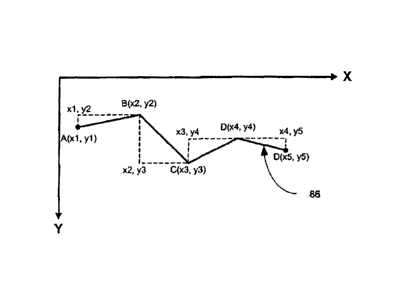
PCT/US2009/062918
[0085] This length is then divided by the resolution of the image to produce
the representative
length in inches on the original plan, or drawing, as provided by Equation (2)
below:
Length (in inches),(length (in pixels))/(image resolution (dpi)) (2)
[0086] This length (in inches) is then multiplied by the blueprint scale
(embedded into the header
of the TIFF image) to produce the actual length (in inches) of the line, as
provided by Equation
(3) below:
Actual length=plan length (in inches) x plan scale (3)
[0087] The measurement calculator 22 then provides this true scale measurement
to the viewer
240 for display to the user. If desired, further measurement conversions can
be performed to
calculate any unit of measurement desired. For example, measurement units can
be converted
from inches to feet or meters by simple multiplication of the unit conversion
factor.
[0088] Next, the area of a rectangle 82 will be calculated with reference to
FIG. 8. Initially, the
user triggers the calculations with a mouse-down event (while the rectangle
annotation is
selected from the drawing tool bar). This event provides the first point of
reference (Xi, Yi) in
pixels. When the user releases the mouse button this triggers a mouse-up
event. This event
provides the second (and final) point of reference (X2, Y2) in pixels. With
these two points ((X1,
Yi) and (X2, Y2)), the measurement calculator 22 can calculate the area
between them (in pixels)
using the Pythagorean Theorem, Equation (4) provided below:
Area (in pixels),(x2-xi) 2+(y2-yi) 2 (4)
[0089] This area is then divided by the squared of the resolution of the image
to produce the
representative area in inches on the original plan, or drawing, as provided by
Equation (5) below:
Area (in inches),(Area (in pixels))/(image resolution (dpi)) 2 (5)
CA 02779525 2012-04-30
WO 2011/053328
PCT/US2009/062918
[0090] This area (in inches) is then squared and multiplied by the square-root
of the blueprint
scale (embedded into the header of the TIFF image) to produce the actual area
(in inches) of the
selected rectangle, as provided by Equation (6) below:
Actual area=(plan area (in inches)) 2 (plan scale) (1/2) (6)
[0091] The measurement calculator 22 then provides this true scale measurement
to the viewer
240 for display to the user. If desired, further measurement conversions can
be performed to
calculate any unit of measurement desired. For example, measurement units can
be converted
from inches to feet or meters by simple multiplication of the unit conversion
factor.
[0092] The area of an ellipse 84 is illustrated next with general reference to
FIG. 9. The user
initially triggers the calculation with a mouse-down event (while the ellipse
annotation is
selected from the drawing tool bar). This event provides the first point of
reference (X1, Yi) in
pixels. Then the user releases the mouse button this triggers a mouse-up
event. This event
provides the second (and final) point of reference (X2, Y2) in pixels. With
these two points ((Xi,
Yi) and (X2, Y2)), the measurement calculator 22 can calculate the area
between them (in pixels)
using the Pythagorean Theorem, Equation (7) provided below:
Area (in pixels)=1-1 [((x2-0/2)+((Y2-y1)/2)] (7)
[0093] This area is then divided by the squared of the resolution of the image
to produce the
representative area in inches on the original plan, or drawing, as provided by
Equation (8) below:
Area (in inches),(Area (in pixels))/(image resolution (dpi)) 2 (8)
[0094] This area (in inches) is then squared and multiplied by the square-root
of the blueprint
scale (embedded into the header of the TIFF image) to produce the actual area
(in inches) of the
selected ellipse, as provided by Equation (9) below:
Actual area=(plan area (in inches)) 2 (plan scale) (1/2) (9)
21
CA 02779525 2012-04-30
WO 2011/053328 PCT/US2009/062918
[0095] The measurement calculator 22 then provides this true scale measurement
to the viewer
240 for display to the user. If desired, further measurement conversions can
be performed to
calculate any unit of measurement desired. For example, measurement units can
be converted
from inches to feet or meters by simple multiplication of the unit conversion
factor.
[0096] The length of a poly-line 86 is calculated next with general reference
to FIG. 10. The user
initially triggers this calculation with a mouse-down event (while the poly-
line annotation is
selected from the drawing tool bar). This event provides the first point of
reference (X1, Yi) in
pixels. The user then moves the mouse and clicks (the left-button) to add
additional nodes [(X2,
Y2). (X3, Y3), . . . (Xn+i, 11+i)]. Once the user is completed with the poly-
line they can either
double-click the left mouse button or single click the right mouse button to
end the poly-line and
trigger the calculation of the length. This provides, for use in the
calculation of the length, (n+1)
nodes and (n) line segments; where 'n' is some arbitrary absolute number. With
this collection of
points the measurement calculator 22 can cycle through each node and calculate
the summation
of the lengths of each line segment using the Pythagorean Theorem (on each
segment
respectively), as provided below by Equation (10):
(1/2)
n
\
Length ( in pixels ) = E - xi )2 (yi i ¨ )2 (10)
[0097] This length is then divided by the resolution of the image to produce
the representative
length in inches on the original plan, or drawing, as provided by Equation
(11) below:
Length (in inches),(length (in pixels))/(image resolution (dpi)) (11)
[0098] This length (in inches) is then multiplied by the blueprint scale
(embedded into the header
of the TIFF image) to produce the actual length (in inches) of the poly-line,
as provided by
Equation (12) below:
Actual length=plan length (in inches) x plan scale (12)
22
CA 02779525 2012-04-30
WO 2011/053328 PCT/US2009/062918
[0099] The measurement calculator 22 then provides this true scale measurement
to the viewer
240 for display to the user. If desired, further measurement conversions can
be performed to
calculate any unit of measurement desired. For example, measurement units can
be converted
from inches to feet or meters by simple multiplication of the unit conversion
factor.
[00100] The area of a polygon 88 is next illustrated with reference to
FIG. 11. The user
initially triggers these calculations with a mouse-down event (while the
polygon annotation is
selected from the drawing tool bar). This event gives us the first point of
reference (Xi, Yi) in
pixels. The end user then moves the mouse and clicks (e.g., the left-button)
to add additional
nodes [(X2, Y2). (X3, Y3), = = = (X 11+i, 11+i)]. Once the user is completed
with the polygon they
can either double-click the left mouse button or single click the right mouse
button to end the
polygon and trigger the calculation of the length. This provides, for use in
the calculation of the
length, with (n+1) nodes and (n) line segments; 'n' is arbitrary and absolute.
With this collection
of points one can iterate through the line segments and get a running total
for the area. This area
is calculated by first identifying a baseline below the polygon, then
identifying a trapezoid whose
sides consist of (1) a single line segment on the polygon, (2) a line from the
rightmost point in
the polygon segment to the baseline which is perpendicular to the baseline,
(3) a segment of the
baseline, and (4) a line from the baseline to the leftmost point in the line
segment (drawn
perpendicular to the baseline). The area of the trapezoid is calculated with
Equation (13) below:
Area ( in pixels ) = ( 1 / 2) (x, yi+1 ¨ xi+1 yi ) ( 13 )
[00101] This area is then divided by the squared of the resolution of the
image to produce
the representative area in inches on the original plan, or drawing, as
provided by Equation (14)
below:
Area (in inches),(Area (in pixels))/(image resolution (dpi)) 2 (14)
[00102] This area (in inches) is then squared and multiplied by the square-
root of the
blueprint scale (embedded into the header of the TIFF image) to produce the
actual area (in
23
CA 02779525 2012-04-30
WO 2011/053328 PCT/US2009/062918
inches) of the selected rectangle, as provided by Equation (15) below:
Actual area=(plan area (in inches)) 2 (plan scale) (112) (15)
[00103] The measurement calculator 22 then provides this true scale
measurement to the
viewer 240 for display to the user. If desired, further measurement
conversions can be performed
to calculate any unit of measurement desired. For example, measurement units
can be converted
from inches to feet or meters by simple multiplication of the unit conversion
factor.
[00104] The present invention permits the user to view the file in an
emergency situation.
For example, if firefighters are dispatched to a burning structure, the
firefighters download the
digital files to a PDA or the like so that they have the entire structural
layout of the building. In
one embodiment, a first user at a workstation provides routing or other
information to a second
user in a structure. The second user receives this information on a PDA, cell
phone, tablet
computer, heads-up display, or the like.
[00105] In one embodiment, the user views the drawing on a viewer 240 such
as a
computer, laptop 28a, PDA 28b, or the like. The blueprint presented on the PDA
provides the
user (emergency response personnel) with accurate measurements of floor space
and distances
between entrances, exits and target locations. Additionally, the system
provides full scaling
functionality. This scaling functionality allows a user to zoom in and out of
a specific area to
provide as much or as little detail as required. In one embodiment, to zoom a
user uses a zoom
tool to select the area that should be zoomed. Alternately, the system will
zoom in preset
increments, i.e., 10%, 20%, 30% around a specific area merely by tapping a
stylus in the desired
zoom area. It should be noted that no matter how much a user magnifies the
display, it remains
accurately scaled.
[00106] Along with measurements, the system can display, visualize and
calculate details
about other structural elements such as stairwells, elevators, entrances,
exits, shaft ways, building
management systems, cooling units, emergency power; emergency command posts,
areas of
refuge and the like. Further, the location of sprinklers, fire extinguishers,
hose hook-ups, risers,
24
CA 02779525 2012-04-30
WO 2011/053328 PCT/US2009/062918
HVAC systems and electrical access panels can also be provided on the layout.
In yet another
embodiment, hazardous materials can also be displayed.
[00107] In one embodiment of the invention, a building security system is
tied into the
network. The security system can provide such data as active alarms such as
fire alarms, smoke
alarms, carbon monoxide alarms, smoke alarms, and the like. In this manner,
emergency workers
can determine problem areas and potential rescue situations. Additionally, a
building's motion
sensors can be tied into the network such that people in the building can be
tracked, thereby
enabling enhanced rescue attempts. For instance, GPS locators can be used to
track people and
equipment. Alternatively, if a hostage situation exists, police can use this
data to plan a terrorist
mitigation or asset recovery mission.
[00108] FIG. 12 is an illustration of a data display, in accordance with
an embodiment of
the present invention. As shown, the display is zoomed in to so the user can
discern a desired
level of detail. In a preferred embodiment, a cursor is used to select a start
point such as
entryway 116 and end point 110. The system programmatically calculates a route
from 116 to
110. Two routes are shown in FIG. 12. A first route, 102, is shown from the
entryway 116 to a
point 110 in a back office. A second route 104 is shown from the entry point
116 to a utility
closet housing a PBX and Hub. In one embodiment, items such as outlets 114,
switches 118, and
telephone jacks are shown. Other items such as electrical conduits, HVAC
systems, and
plumbing are shown. The display provides data from motion sensors 100, heat
and smoke
alarms, and door and window sensors, which are tied to the display.
[00109] In one embodiment, a kiosk 120 is present. Building visitors use
the kiosk 120 as
a guide. In one embodiment, patrons use the kiosk as a directory. Patrons
either selects a
destination graphically, e.g., a desired office 110, or selects from a
directory listing. Either way,
the route, and if desired route adjacent areas of interest such as a building
locations or hazard, are
displayed.
[00110] Users use zoom tool 108 a user zooms in and out of a specific area
to provide as
much or as little detail as required. In one embodiment, to zoom, zoom tool
108 selects the
CA 02779525 2012-04-30
WO 2011/053328 PCT/US2009/062918
specific area to be magnified. Alternately, the system will magnify in preset
increments, i.e., 5%,
10%, 15%, etc. using the selected area as the center of the area to be
magnified. In another
embodiment, the preset increments are selectable by the user. It should be
noted that accurate
scaling of the image and accurate scaling of all measurements are maintained
at each
magnification point.
[00111] As described above, the system and method according to the present
invention
provides the ability to take paper based original drawings and provide scaled
digitized images
that allow for accurate point to point measurement and routing. The foregoing
embodiments are
given by way of example for the purpose of teaching the method and system of
the present
invention. The present invention is not limited to these embodiments and one
skilled in the art
may affect various changes and modification within the spirit of the invention
as defined in the
appended claims.
[00112] Also as mentioned above, the present invention can be used by
anyone including
and not limited to firemen, emergency response, command and control, police,
EMT, utility
workers, military, and building operations, management tenants and ownership
as well as facility
engineers. In one embodiment the invention can be implemented for a city
emergency operations
center with access being granted to local, federal and state fire, police and
emergency services
users.
[00113] Another method in accordance with the present invention is shown
now in FIG.
13. At block 200 a document is scanned or otherwise digitized and the original
document image
scale information, DPI of the scan and original paper size is captured and
embedded into the
digital file header of a two dimensional digital raster image. The scanned
document may include
floor plans from a single building, or more likely a collection of buildings.
[00114] A true scaled three dimensional virtual digital model rendering
(also called the 3D
digital image or 3D digital rendering) is created based on the two dimensional
digital raster
image. Specifically, the viewer and the associated tool sets are used
manually, or through
programmatic steps, to annotate the 2D digital raster image so that the
properties and positions
26
CA 02779525 2012-04-30
WO 2011/053328 PCT/US2009/062918
of the 2D annotations are programmatically translated to create a scene graph
which is then used
to create the associated-3D digital image. See block 205. The scene graph
lists the objects,
properties, and transforms that describe the 3D digital image. The scene graph
is organized by
loose groups of similar object types rather than any specific order of
objects.
[00115] Once the 2D digital raster image file and the 3D virtual model
files have been
created, each file may be organized and stored as individual yet associated
files using a file
system in the database sever 14, the memory of any computing device or a
central data
repository. See block 210. Individual documents are stored in a file server
and associated to
database records. Documents may preferably be organized in the database by
building and floor
or some universal standard.
[00116] The user may search the database for the digital image file to be
viewed at a
workstation 16 using a computer or laptop 28a or the like. See block 220.
Users of the database
can locate and view individual digital plans or groups of digital plans. The
database can be
located on a closed network, a web accessible network or a localized computing
device with no
network connectivity.
[00117] The user can query the database to locate a specific digital image
or group of
digital images (block 230) such as an entire 3D building, a digitized floor
plan document or the
individual floor 3D scene. The selected digital image file is then distributed
to the workstation
via the network 24 and viewed, to-scale on a dual 3D/2D digital image
display/viewer 240. The
digital viewer 240 may include but is not limited to synchronized graphic
rendering devices,
synchronized user interactive graphic displays, linked graphic
representations, real time event
linked display mechanisms, synchronized horizontal display surfaces,
synchronized holographic
displays, synchronized graphic screens, dual monitor heads up displays, auto
stereoscopic
displays and immersive graphic environment. In one embodiment, the digital
image file is pre-
populated onto mobile computer systems with 3D enabled video graphic hardware
and software.
[00118] The digital image display/viewer 240 can open and render the
digital image files
and retrieve the original image/document scale information that is embedded in
the 2D digital
27
CA 02779525 2012-04-30
WO 2011/053328 PCT/US2009/062918
image header. The digital image display/viewer 240 has a multiple document
interface having
display means, windows or view ports that are linked and coordinated and can
be seen
simultaneously.
[00119] An illustrative user interface of the display/viewer 240 is shown
in FIG. 14
comprising an application shell 243, two document view ports (a 3D window 242
being 3D
graphics enabled and a 2D window 244 being 2D graphics enabled), a basic set
of drawing tools
and a menu interface to activate functionality and interact with the 3D and 2D
displays. Both the
3D window 242 and 2D window 244 can be sized and positioned to the user's
preference. In one
instance, the 3D window 242 occupies 40% of the left hand side (LVP) of the
display/viewer 240
and the 2D window 244 occupies 40% of the right hand side (RVP) of the screen.
[00120] Images displayed on the 3D display 242 are true scaled three
dimensional digital
renderings that are initially viewed as a ground plain view wherein the user
perspective is
parallel to the plain of the document surface. The view angle can be manually
changed and
rotated on the X, Y or Z axis permitting the user a view perspective at any
desired angle or
height. See Fig. 14. Images displayed on the 2D window 244 are viewed
perpendicular to the
surface of the document. For instance a scaled digital floor plan or an
architectural drawing view
in 2D will be viewed in plan view which is maintained when the document is
zoomed or rotated
or otherwise manipulated. The 2D digital raster image is the master file, real
data, and is the
origination point for data as scale data is embedded and read from the digital
image rendered in
this location for both the 3D and 2D windows.
[00121] The simultaneous viewer 240 serves as a tool that provides the
user with an
enhanced awareness of a situation or environment and an overall intelligence
of the structure
shown in the drawings. The user can manipulate the digital images using the
simultaneous
viewer 240 using tools employed with the viewer 240. For instance, the user
can identify start
and end points on an image displayed in a select window (block 250), use the
shortest path tool
to find the fastest route between two graphically marked/user chosen points
with no restrictions
or limitations on the end and start point locations in context to the building
image (block 260),
select an stairwell and set it to be an Evacuation stairwell which will then
only allow that
28
CA 02779525 2012-04-30
WO 2011/053328 PCT/US2009/062918
stairwell to be used for routes calculated from a building floor down through
the structure and /
or an attack stairwell which will then only allow that stairwell to be used
for routes calculated
from a building location up through the structure and force the Shortest Path
tool to use that
stairwell as a first node in the route calculation (block 265), calculate the
shortest path between
points and display the total distance using the shortest path algorithm and
the embedded scale
information (block 270), graphically display the shortest path diagrammed in
the 3D window 242
(block 280) and 2D window 244 (block 285) and also view the true scale
measurement of the
shortest calculated path (block 290). Additionally the calculated path data,
i.e. the graphic
display data and the true-scale path measurement data can be selected in the
3D window and
with a mouse command and an application dialog appears that allows the
calculated path to be
named and saved for future retrieval and use (block 295).
[00122] Creating The Two Dimensional Digital Raster Floor Plan Image
[00123] Referring back to block 220, the scanned document creates a true-
scale 2D digital
image, which is displayed in the 2D window 244. The captured scale data is
embedded in the
TIFF header of the 2D digital image. Each object represented in the 2D digital
image of the 2D
window 244 is represented by a 2D primitive, usually a line for a wall, or a
rectangle for a door,
window, or other object. The shapes represented by the digital image in the 2D
window 244 may
be either 2D only data (being data that does not have 3D-associated
representations) or data with
3D-associated representations, also called 3D related objects. The 3D-related
objects have
additional information relating to type, orientation, off-ground position and
object height that is
not realistically presentable in the 2D window.
[00124] Creating The True Scaled Three Dimensional Virtual Digital Model
Image
[00125] As mentioned above, the scale information embedded in the original
raster 2D
floor plan is also used to construct a true scaled three dimensional digital
model image,
specifically the scale information is translated into associated 3D virtual
models via the scene
graph. The 3D digital image/3D digital rendering displayed in the 3D window
242 is prepared
using the 3D-related objects data graphically overlaid on the original 2D
digital image displayed
29
CA 02779525 2015-03-25
79724-17
in 2D window 244. Each object in the 2D data set is evaluated to extract
information contained
in 3D related objects and any predefined model associated with the object is
added tp the scene
graph, (2D Data annotation objects representing walls do not have separate
associated models.
The 2D wall annotations are directly extruded into true scale 3D geometry
elements.) Then the
3D objects are arranged using positional coordinate information, 3D object
data structures are
created, and pointers to the 3D structures are added to the associated 2D
object data sets.
[00126] Using the 3D digital image, a user can use a computer mouse to
manually
navigate the 3D virtual model of the building and virtually walk through rooms
and hallways of
the model displayed on the 3D window 242. A 3D window camera is used with the
3D window
242 to assist in viewing the path taken in the 3D virtual model. The 3D window
camera can be
set in a location to define the view of the structure that is presented in the
3D window 242 and =
render the scene from the camera's point of view. The path taken in the 3D
virtual model can be=
viewed as if the virtual moving camera is positioned on a person's head.
[00127] The display/viewer 240, the 3D window 242 and 2D window 244 are
designed to
work in cooperative form. For instance, the 3D window 242 and the 2D window
244 may be
child applications of the application shell (a parent application) 243, or two
separate applications
may be tied to a third application, or all three applications are tied
together. As a result, using the
display/viewer 240 the user can not only simultaneously view the 2D digital
image of a floor
plan in the 2D window 244 and the associated 3D digital model image of the
structures and
objects of the floor plan 242 but also synchronize, in real-time an action
taken in one window
and display it in the other window. Furthermore, using the tools employed with
the
display/viewer 240 the user can manipulate or derive information from the
digital images. As an
option, the present invention allows the user to open one window, 242 (see
Fig. 15) or 244 (see .
= Fig. 16), and manipulate the digital image using only the open window
alone. All changes or =
other input made in the open window is tracked and relayed to the closed
window when it is
opened again, for instance, by the parent application 243 (see Fig. 17) when
the parent
application is used to manage all changes made in the 3D window 242 and 2D
window 244.
=
CA 02779525 2012-04-30
WO 2011/053328 PCT/US2009/062918
[00128] The 3D window 242 and 2D window 244 of the display/viewer 240 are
true to
scale, coordinate matched, and linked in real time providing an interaction
between the images in
each the 3D and 2D windows 242, 244. The mechanism by which the objects are
kept accurately
synchronized is accomplished by associating scale, selection events and
coordinates from one
window 242, 244 to the other window 244, 242, respectively.
[00129] SYNCHRONIZATION USING SCALE
[00130] As described above, the scale information of the original
image/document is
embedded in the digital image header. This data is retrieved and used by the
digital image viewer
240. As the 3D digital image is associated to and based on the 2D digital
image, the true scale
value is the same in the two windows 242, 244. In some embodiments the scale
between the
windows 242, 244 could be different. In such cases an algorithm may be used to
translate the
scale from one window to the other.
[00131] SYNCHRONIZATION USING SELECTION EVENTS
[00132] Selection event synchronization takes advantage of the fact that
each object
movement or position change (user input) creates a software
selection/transform event. These
selection events provide the identity and updated position for the object.
Depending on which
window the user employs, the selection events or action taken by the user in
one window is
simultaneously repeated (causes a re-draw) in the other window. Generally,
when an object is
moved, the selected object is flagged, a 2D selection event list is cataloging
each
flagged/selected object (logged selection event) and an update is affected
using the 2D selection
event list in the corresponding window. Variations are present in this process
depending on
which window is used to create the selection event.
31
CA 02779525 2012-04-30
WO 2011/053328 PCT/US2009/062918
[00133] Changes made to objects in the 2D window
[00134] When a user makes a change to one or several objects in the 2D
window 244, a
flag is set by the selected object and the flagged object is put in a 2D
selection event list. An Idle
State Processing Program, is part of the parent application, is then employed
to update the 3D
digital image. For instance when deleting an object from the 2D window the
Idle State
Processing Program will cycle through the 2D selection event list checking the
flagged objects
and deleting the corresponding 3D representation of the flagged 2D object in
the scene graph.
The 3D data is deleted during an update of the 3D digital model image as it is
translated from the
real 2D data.
[00135] The 2D selection event list containing the updated information is
then iterated
through and new 3D objects are generated and placed into the scene graph.
Accordingly, to
effect a change to an object's 3D representation, it must be located in the
scene graph, its data
updated, and the scene graph re-rendered. The replacement of the objects
straightforward and
efficient given that the scene graph is organized as loose groups of similar
object types. The
scene graph can be manipulated so that updates do not cause the entire scene
to re-render only
the affected objects for which a selection event is recorded.
[00136] To prevent thrashing (causing too many re-renders per object move)
the Idle State
Processing Program is only initiated when an idle state in the application is
detected by the
system, such as when there is no selection event, change or input from the
user. Here, when the
Idle State Processing Program is opened, changes are made to the scene graph
to update the 3D
digital image. Unnecessary changes are further controlled by keeping track of
which objects
have been selected. Both the 3D and 2D data sets contain lists of the
currently selected objects,
and it is only the objects in these smaller lists that will be changed.
Accordingly, once the 3D
digital image has been updated, flags are set to prevent the 3D-side-change
selection events from
triggering changes on the 2D side.
32
CA 02779525 2012-04-30
WO 2011/053328 PCT/US2009/062918
[00137] Changes made to objects in the 3D window
[00138] When a user moves or rotates an object in the 3D window 242 a
selection event is
triggered, a flag is placed by the 3D selected object in the scene graph and a
3D selection event
list is created. The selection event occurring in the 3D window 242 possesses
the identity of the
object and transform information for the action taken. The transform is the
new X, Y and Z
positional and rotational angle information that has been applied to the 3D
object. The
transforms are applied to only the selected 2D object(s) in the 3D selection
event list. Unlike the
changes initiated in the 2D window 244, here, the selected 2D object data is
not deleted but
rather is directly modified because 2D data is treated as the real or source
data.
[00139] The selected 2D data is updated using known scaling factors and
position and
orientation information needed to correctly show on the 2D digital image or
representation in the
2D window 244. Additional information such as z-axis rotation or vertical
position information
cannot be shown in the 2D window, but is saved in the object's data set.
[00140] Here too, changes are made in the background of the 2D digital
image to effect an
update after the Idle State Processing Program detects no activity and flags
are set that prevent
the already updated 2D digital image components new positions from triggering
further 3D
selection events.
[00141] SYNCHRONIZATION USING COORDINATES
[00142] The coordinate matched feature of the dual three-dimensional / two-
dimensional
visual display/viewer 240 is based on a non-rendered mathematically accurate
grid system. Each
of the 3D and 2D digital images has a non-rendered grid positioned on top
thereon reflecting the
precise pixel dimensions of the document. The coordinate system of each window
in the
display/viewer 240 is linked to a common referenced point or cross referenced
point usually
being the upper-left corner of the floor plan as the 0, 0 point.
33
CA 02779525 2012-04-30
WO 2011/053328 PCT/US2009/062918
[00143] Thus, a 2000 W x 1500 H pixel document has a corresponding 2000 x
1500 space
grid on top of it. This grid is a computed virtual entity that is not drawn or
seen and can extend
infinitely on any axis. When viewing the entirety of the document at 0% zoom,
the upper left
hand corner of the document is the 0 Y (Vertical Axis), 0 X (Horizontal Axis)
and, when
applicable, 0 Z (Three -Dimensional axis).
[00144] The linking of coordinate positions for data objects displayed in
each the 2D
window 244 and 3D window 242 of the display/viewer 240 is dependent on the non-
rendered
grid. A two-way relationship is created by the linking of the coordinate
systems. Thus when an
object is moved or annotations are made, manually or programmatically, in the
3D window 242,
the corresponding 2D graphic representation in the 2D window 244 will move
near
simultaneously and vice versa.
[00145] The coordinate system inherent in the display/viewer 240 enables
linking by
allowing a discreet set of pixels to be colored graphically to mark a chosen
shape, line or point.
Indeed a point marker could be as small as 1 pixel W 1 pixel H. Because pixels
have a definitive
size that cannot be divided graphic representations of lines and shapes are
always estimations.
[00146] The coordinate system allows relative positions to be defined and
corresponded to
other relative or arbitrary positions. The coordinate system of the present
invention may even
correspond to real world locations defined by coordinates of outside systems
such as geographic
coordinate system including latitude and longitude, e.g. a GIS systems. The
display/viewer 240
can receive coordinate input from a third or outside coordinate system as long
as the external
coordinate grid and scales can be converted to the coordinate system shared by
the windows 242,
244. Such conversion occurs by translating the disparate coordinate system
scales and defining
at least one common reference point. Preferably multiple common reference
points would be
established.
[00147] By using outside coordinate systems, the present invention allows
users to receive
coordinate data describing the location of an asset or object based on the
Geographic Coordinate
34
CA 02779525 2012-04-30
WO 2011/053328 PCT/US2009/062918
system and translate those coordinates to an exact spot on the 3D and 2D
windows 242, 244
representations of a structure.
[00148] In practice, a point defined graphically in the 2D window 244 can
be calculated to
have a certain coordinate position because of the grid and a relative true
scale measured size
resulting from scale data that is embedded in the digital image header.
[00149] The present invention combines contextual and structurally
connected visual
information to allow the user to obtain an enhanced situational awareness of a
structure and to
intelligently navigate through the structure. For instance, users can
simultaneously see their
immediate true scale spatial environment in the 3D window 242, (along with
what the room
looks like) and their accurate, true scale orientation (with respect to the
end point/goal) and
current position in the building as shown in the 2D image displayed on the 2D
window 244.
[00150] The coordinate-linked, dual and simultaneous nature of the 3D / 2D
display/viewer 240 when combined with the tools of the viewer 240 allow the
user to interact
with the digital images in each window 242, 244 and thus better understand an
environment.
The user can manually trace out a route, experience (virtually walkthrough)
the route, describe
the route's environment during the virtual walkthrough, see a real time
position indicator for the
assets location in the 2D view port, and obtain the true scale measurement
between objects and
locations or of the navigated path displayed and saved. Also, once the 3D
visual navigation of
the structure can be recorded, it can be made distributable using standard
video files outputs.
[00151] TOOLS
[00152] The tools employed with the display/viewer 240 include but are not
limited to a
basic scale measurement calculator 22, a basic graphic drawing tool set
capable of making
precise colored annotations on the digital image, a Find Shortest Path Tool
300, a Path Barrier
Tool 360, a Door Detection Tool 330 and an Evacuation Simulation Tool. These
tools may be
managed by the parent application 243 and can be used in either window 242,
244.
CA 02779525 2012-04-30
WO 2011/053328 PCT/US2009/062918
[00153] Drawing Tools
[00154] As described above, the drawing tools 410 permit a user to
construct lines, shapes
and points with vector or raster graphic drawings. These drawings are then
presented on a layer
on top of the original drawing, digital document. Using the display/viewer 240
of the present
invention, the user can trace out a path on the 2D window 244 using the basic
drawing tools and
have the same path rendered precisely and programmatically in the 3D window
242. The path
shown in the 3D window is contextually correct being true to scale and
reflecting the accurate
measurements of a structure. A route virtually walked in the 3D window 242 can
be visually
recorded as a user generated animation, saved and played back, as discussed
below.
[00155] Find Shortest Path Tool
[00156] Referring to Fig. 18 A, the Find Shortest Path Tool 300 uses an
algorithm to
automatically calculate and allow the visual plotting of the shortest path
between points selected
in either the 3D or 2D windows. This Find Shortest Path Tool works by
transforming the map
matrix and distance/area data present in the digital document floor plan image
and automatically
calculates the shortest path. The shortest calculated path and the associated
path true scale
measurements are known and able to be calculated as a result of the scale that
is embedded into
the header of the TIFF image.
[00157] In practice, a user selects the Find Shortest Path tool 300 then
graphically marks
start and end points on one digital image in a selected window. For example,
an emergency
personnel can mark the start point 302 as being a doorway in a building and
mark the end point
304 as being a computer classroom in which a victim or hostage is said to be
located and using
the Find Shortest Path tool 300 calculate the shortest path 306 between the
two points. See Figs.
18A and 18B. The tool 300 can be used on a single floor, as shown in Figs. 18A
and 18B, or
across multiple floors, see Find Shortest Path tool 301 as shown in Fig. 18C.
When the tool 301
is used across multiple floors, it will identify and traverse the buildings
unique set of emergency
stairwells; entrances and exits during route calculations. See Fig. 18C
showing start point 312,
end point 314 and route 316.
36
CA 02779525 2012-04-30
WO 2011/053328 PCT/US2009/062918
[00158] This tool 300, 301 can assist emergency response or other
personnel in navigating
from the doorway to the stairwell even when the floor of a building is
visually or physically
obstructed. This Find Shortest Path tool may also be used by emergency
response personnel to
determine the fastest route to an emergency location inside a building even
before arriving on
scene or when having no prior knowledge of the building's interior structure,
saving precious
time.
[00159] In a preferred embodiment, the shortest path is represented in the
2D window 244
by a colored line 306 that follows the exact calculated path through the
structural drawing and in
the 3D window 242 by a red 3D floating poly line shape 308. See Fig. 18B. A
visual display of
the true scale measured path is also shown. After the path is calculated and
visually plotted in
both 3D and 2D windows 244, 242 the user can position the 3D window camera to
the preferred
structural entry point and easily visualize, and identify the beginning of the
shortest path. The
shortest path marker and path directions can be communicated to the fire
rescue team or obtained
by the team themselves on site. Additionally the calculated route can be
automatically played
back as a walkthrough animation allowing emergency personnel to see the entire
route and all
the building structural elements, objects of interest and hazards along the
way.
[00160] Path Barrier Tool
[00161] Fig. 19 shows the Path Barrier Tool 360,which is used to
graphically mark
pathway obstructions and hazards that will prevent passage through a
particular area or as a
general hazard marker. The user selects the Barrier tool then graphically
marks the affected area
in either window to trigger the programmatic placement of a scaled visual "Do
Not Enter"
marker into the window data sets. This action accurately changes the visual
geometry of the 3D
and 2D scenes, 364, 362 respectively, and mathematically alters the makeup of
the map matrix
used by the Find Path Tool.
[00162] After the obstructed areas have been marked on at least one of the
images or
renderings, the invention can automatically or manually recalculate and
visually render the
shortest path options taking full consideration of the reduced route options.
This tool 360 can be
37
CA 02779525 2012-04-30
WO 2011/053328 PCT/US2009/062918
used by emergency response personnel to instantly and accurately update
tactical response plans
and instructions using real time events and user interaction with the
invention to transform map
and measurement data into site specific real time contextual intelligence.
[00163] Door Detection Tool
[00164] The Door Detection Tool 330, for instance, may be employed with
the 3D
window 242 and is used to automatically and programmatically count the doors
in a selected
path or virtually passed by the invention user. See Fig. 20. A running count
may be visually
displayed to the user of this tool in the 3D window. For instance, a dialogue
box may appear to
show each the left door count 332 and right door count 334. The total door
count can be
communicated to the fire rescue team or obtained by the team themselves on
site. Fire rescue
teams can use the Door Detection Tool to count the number doors or determine
locations of
doors in a selected path and even verify that they are on the right path. The
Door Detection Tool
is therefore also useful in mitigating navigation through low visibility
environments.
[00165] 3D Record Path Tool
[00166] The display/viewer 240 may also employ a 3D Record Path Tool 350.
See Fig.
21. This tool 350 is best used with the 3D window 242, however with some
modifications this
tool could also be used in the 2D window 244.
[00167] The 3D Record Path Tool 350 allows application users to visually
record every
virtual movement and scene being viewed in the 3D window 242. When the 3D
Record Path tool
is turned on, the 3D camera's true scale start point 352, the exact path taken
354 and current
position 356 in the 3D digital image are simultaneously and in real-time
graphically displayed on
the 2D digital image floor plan shown in the 2D window 244. The 3D window 242
will show the
3D view of the path 354 shown in the 2D window. Reference number 358 shows the
3D view
taken at the current position 356 of the path 354 shown in the 2D window 244.
So as the user
virtually walks through the 3D floor plan model, the user's virtual position
is directly associated
38
CA 02779525 2012-04-30
WO 2011/053328 PCT/US2009/062918
to an exact coordinate on the original 2D floor plan. Also, the exact, true
scale measurement of
the path's length can be shown in the measurement box 400.
[00168] The visual marker used in the 2D window 244 may be a red line that
is drawn in a
visual layer on top of the 2D image. The red line will essentially trace the
path the user is
walking in the 3D view and plot marker points or route nodes along the way. A
measurement
dialog may be employed with the present invention to display the accurate
measured length of
the recorded path in real time using the embedded scale data.
[00169] Once the 3D Record Path tool is stopped, the user not only sees
the exact path
taken along with starting and ending points, but can replay the virtual 3D
path that was walked in
the 3D window 242 or save the entire 3D visual sequence, i.e. animated movie,
out to a standard
.avi, mp4 or a variety of other standard video formats for distribution.
[00170] The 3D Record Path functionality can be used in a variety of
situations and
contexts. For example, a user can create an accurate, to-scale virtual model
of a museum floor
plan by scanning paper drawings of a section of a museum. When the 3D digital
image is
created, any furniture, sculpture, and wall hanging art objects can be
accurately modeled and
represented inside the 3D museum floor plan. The application user could then
walk through the
virtual 3D museum and initiate the 3D Record Path tool to view an accurate
visual representation
(or movie) of the path taken. This may be useful to guide museum patrons
through a museum
exhibit, or allow a remote museum curator to view exact accurate museum and
art layouts in
another country without physically being present at the viewed museum. This
tool could also be
used to market materials and virtual art shows as well as to curate entire
shows from remote
locations without the expense of onsite visits.
[00171] In another instance, the 3D Record Path Tool could be employed by
emergency
crews to gain invaluable insight into the interior layouts of buildings during
emergency
situations. Using the 3D Record Path Tool, tactical information gathered on
scene can be used in
conjunction with the 3D floor plan models and allow users to gain a detailed,
fully to-scale visual
guide of emergency locations. Also, with this tool, the user can plot entry or
exit routes in a
39
CA 02779525 2012-04-30
WO 2011/053328 PCT/US2009/062918
structure, automatically view the entire length of the path in a true scale 3D
animation and
intelligently adjust the navigation path based on architectural and hazard
elements that can only
be visualized and incorporated into the digital images using the present
invention. These
recorded 3D floor plan visualizations can be used to make further tactical
decisions based on the
information being rendered and the novel manner of presentation at command and
control or sent
out into the field as pre-planning guides for emergency responders on scene.
All these uses
maintain accurate scale and measurement data throughout because of the
embedded scale in the
TIFF header. It should also be noted that the raster image created using the
tools of the present
invention is transmitted from one source to another maintaining true scale
throughout the entire
process and end user activity.
[00172] Evacuation Simulation Tool
[00173] The Evacuation Simulation Tool allows users of the 3D / 2D
synchronized
viewer 240 to extend the data calculated by the shortest path tool 300 to
larger scale simulations.
In essence, once a shortest path has been calculated by the Shortest Path Tool
300 and the path
has been graphically displayed in the 3D and 2D viewports, the end user can
select the path in
the 3D or 2D window and activate a new function through the right click menu.
[00174] This Evacuation Simulation tool would work with Population Density
data
encoded in the building 3D / 2D data set to describe the number of persons
that are in the vicinity
of the Shortest Path Start Point. The Evacuation Simulation tool would then
use the true scale
dimension information embedded in the tiff header to calculate the dimension
of the surrounding
area and the area taken by the estimated population. In combination with a
virtual crowd
simulation, point particle method or flock algorithm the Evacuation Simulation
tool would then
calculate how long it will take to move the total estimated number of people
encoded in the
Population Density data along the true scale calculated shortest path, through
all the structural
bottlenecks to the end path location. Users would simulate/select either a
time of day or an
incident description which would alter the estimated Population Density data
in the building 3D
and 2D data sets. Then the simulator would take into account the prepared
density information
for the various parts of the building that the path traverses. Time estimates
would be displayed
CA 02779525 2012-04-30
WO 2011/053328 PCT/US2009/062918
back to the end use as well as the ability to run a visual playback of the
group of virtual people
moving along the evacuation route.
[00175] Each of the tools described above can be used alone or in any
combination. For
instance, the user can combine the Find Shortest Path Tool 300, 301 and the 3D
Record Path
Tool 360 to not only follow the shortest path in one window that is
simultaneously being plotted
in the corresponding window, but also view a recorded movie of the selected
path taken from the
3D digital rendering.
[00176] Using the present invention, the user may also manually record on
either digital
image the presence of additional hazards, obstructions or other data noticed
on-scene or while
watching the replay of the recorded 3D virtual path from the 3D Record Path
Tool. This added
information can be then distributed/relayed to the other emergency responders
inside or within
the real world building location or else where permitting quick entry and exit
of the building.
This feature allows emergency team leaders and command and control personnel
to continually
update their response plans as new information is obtained by using the
invention. Information
that, would in part, not be available to the end user without the invention.
[00177] TRACKING REAL WORLD EMERGENCY RESPONDER
[00178] The true scale, coordinate-matched, linked in-real time, dual
three-dimensional /
two-dimensional visual display/viewer 240 can be used to track real world
objects (assets) and
simultaneously mark, graphically, their location on a 2D floor plan and as a
corresponding object
in the 3D window 242. This combination of contextually related visual
environments enables
the transformation of two independent streams of data into one coherent piece
of information.
[00179] In practice an emergency responder can be outfitted with a
transmitter / receiver
device. These devices use a location method to identify where an asset is in
relation to some
scaled, coordinate based system. For example, as mentioned above, asset
coordinates can be
41
CA 02779525 2012-04-30
WO 2011/053328 PCT/US2009/062918
obtained in relation to the GPS Geographic Coordinate system or a localized
location grid that
creates a grid entity and ties asset location to a coordinate within that
localized grid.
[00180] For example, a responder can be outfitted with a GPS device
capable of
receiving/transmitting location or identification signals to either a receiver
location outside of a
building or a receiver already existing within the structure which may be
outfitted with a disaster
proof signal repeating and amplifying unit. These repeating signals and
amplifying units are
designed to pick up the lower strength / lower powered personal GPS device
signals and
retransmit the signals to external receivers so that location data can be
calculated.
[00181] In another example, the responder can also be outfitted with a
radio transmitter
and receiver, this can be referred to as the asset tag. In systems that are
well known in the art, a
localized set of computer connected mobile transceivers send out radio signals
and receive
signals back from the asset tags. The present invention may employ a
triangulation or a
multilateration method, known in the art, in detecting coordinates for an
asset or emergency
responder. Depending on the type of system implemented the asset tags location
can be
determined in reference to this localized grid in a variety of ways depending
on the type, strength
and broadcast reach of the asset tag and receiver stations.
[00182] Once an object's location (such as an emergency responder's
location) is
calculated using the methods described above the coordinate grid and scale can
be translated to
align with the coordinate system of the present invention. A reference point
common among all
the coordinate systems is established so that locations can be plotted in
relation to this point.
[00183] The asset coordinate data of the emergency responder can be
graphically rendered
simultaneously using the 3D / 2D dual visual display/viewer 240 of the present
invention. As the
asset location coordinate data is updated, the location of the object or
emergency responder is
also updated in the 3D and 2D digital images.
42
CA 02779525 2012-04-30
WO 2011/053328 PCT/US2009/062918
[00184] The display/viewer 240 and the tools of the present invention,
provide the user
with an understanding of the contextual 3D / 2D visual environment by allowing
the user to see
an object's (or asset's) location rendered in a manner not realized by the
prior art. The present
invention is also useful as an analysis tool. For instance, if an asset is
navigating a structure in a
compromised, hazardous, or visually impaired situation the immediate dangers,
percentage of
route completion and alternative routes in reaction to changing conditions on
scene can be
evaluated and reacted to with information transformed by the present
invention.
[00185] EXAMPLE
[00186] The present invention may be described using the below non-
limiting example.
[00187] A fire is reported burning on the third floor of a four-story
structure. The
emergency responders uses a laptop 28a to access the floor plan data of the
burning building
either on-site or on route to the building. Once the floor is located, the
emergency responder can
open the desired digital images using the display/viewer 240 and manipulate
the data in several
different ways all of which can occur simultaneously.
[00188] The user can identify all entry and exit points for the structure
using the 2D
window 244 in the digital image display/viewer 240 and the select the Find
Shortest Path Tool to
determine the shortest and fastest path from one point on the floor to an exit
point. Once the path
has been calculated and visually plotted in both the 3D and 2D windows 242,
244 the user can
place the 3D window camera to the preferred structural entry point or their
current position in the
building and view the calculated path. The 3D Record Path tool may be employed
at this time to
record the path taken in the 3D digital image (3D virtual model) of the
building. This video can
be replayed back or distributed by wire or wirelessly to other emergency
personnel. Native to
the standard video formats created, end users of this type of system
transformed, user generated
content will not need to be system users themselves to share in the visual
intelligence.
43
CA 02779525 2012-04-30
WO 2011/053328 PCT/US2009/062918
[00189] If real-time, on-scene date being received by emergency crews
indicates that the
path shown by the Find Shortest Path tool is obstructed or cannot be taken,
then the user can
reroute the path using the Find Shortest Path tool to calculate another path
to the exit point.
Using the counterpart Barrier Tool 360 users can mark the hazard/obstruction
identified by the
on scene emergency crew in the 3D or 2D window triggering the simultaneous
insertion of a
visual to-scale representations of the obstruction. This visual representation
can be of the actual
obstruction or a geometric shape textured mapped with a globally standard
emergency symbol.
Users can mark multiple to scale barriers altering the data parameters of the
mapped environment
and ultimately affecting the intelligence and measured route options
calculated from the
underlying document image data. Finally, to assist the emergency personnel in
way finding the
smoke-filled floor, the Door Detection Tool may be used to count the number of
doorways or
entryways until the desired end point is reached. This data is essential to
visually impaired
environments where tactile verification is needed for navigation. This data
can be found on
almost any typical architectural floor plan but it must be manually tabulated
along a desired route
for the data to be meaningful or offer any usable intelligence. The use of the
current invention
overcomes this serious deficiency in the art.
[00190] If the building is internally equipped with a receiver / amplifier
and the
emergency responder involved in an interior attack or as part of a rescue
company in a fire hot
zone is equipped with a GPS device or radio transmitter, outside personnel may
be able to
visually track the responder's exact coordinate within the third floor of the
building and verbally
instruct the responder to any new occurrences or changes to the emergency
situation or with
additional information based on the systems visual display to assist the
responder in dealing with
conditions that they are discovering and reporting back to outside personnel
in the interior of the
building.
[00191] Many modifications and other embodiments of the inventions set
forth herein will
come to mind to one skilled in the art to which these inventions pertain
having the benefit of the
teachings presented in the foregoing descriptions and the associated drawings.
Therefore, it is to
be understood that the inventions are not to be limited to the specific
embodiments disclosed and
that modifications and other embodiments are intended to be included within
the scope of the
44
CA 02779525 2012-04-30
WO 2011/053328
PCT/US2009/062918
appended claims. Although specific terms are employed herein, they are used in
a generic and
descriptive sense only and not for purposes of limitation.