Note: Descriptions are shown in the official language in which they were submitted.
CA 02779531 2012-05-01
DESCRIPTION
Title of Invention
MILK METER, MILK VOLUME MEASURING METHOD, AND
MILKING DEVICE
Technical Field
0001
The present invention relates to a milk meter connected to the middle of a
milk
transfer line for feeding milk milked by a milking machine for measuring a
milk volume,
a milk volume measuring method, and a milking device.
Background Art
0002
A milk meter connected to the middle of a milk transfer line for measuring a
milk
volume has been known, and this type of milk meters are divided into a non-
retaining
type that directly measures flowing milk and a retaining type that temporarily
retains the
flowing milk in a measuring container portion and measuring the same.
0003
The non-retaining type has an advantage of a small size and simple
configuration
but has a drawback in measuring accuracy. Thus, the retaining type is required
for
ensuring high measuring accuracy. The retaining type is usually constituted by
a
measuring container portion connected to the middle of a milk transfer line
and capable
of retaining milk inflowing through an inlet, a liquid level detection portion
disposed
inside this measuring container portion and having a low-position electrode
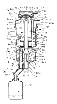
portion
detecting the liquid level at a low position of the retained milk and a high-
position
electrode portion for detecting the liquid level at a high position of the
retained milk, a
1
CA 02779531 2012-05-01
valve mechanism portion capable of opening/closing an outlet provided on the
lower
part of the measuring container portion, and a control system for controlling
the valve
mechanism portion so that the outlet is closed upon detection by the low-
position
electrode portion and the outlet is opened upon detection by the high-position
electrode
portion. As this retaining type milk meter, a milk meter disclosed in Patent
Literature
1 is known.
Citation List
Patent Literature
0004
Patent Literature: U.S. Patent No. 4,391,222
Summary of Invention
Technical Problem
0005
However, the prior-art milk meter disclosed in the above-described Patent
Document 1 has the following problems.
0006
First, milk transferred from a milk tube on the upstream side is retained to a
certain
level of the measuring container portion and then, an on/off valve attached to
the outlet
on the bottom part is opened to discharge the milk to a milk tube on the
downstream
side through the outlet. Moreover, since the milk transferred to the measuring
container portion is mixed with air, the measuring container portion also
works as a
gas-liquid separation chamber which separates air from the milk. The air is
discharged
from a vacuum line faced with a roof portion of the measuring container
portion and
then, added to the milk discharged through the outlet in the measuring
container portion
2
CA 02779531 2013-12-05
VVH-13867A
SN 2,779,531
again, so that the milk is mixed with air and delivered to the milk tube on
the
downstream side. In this case, since a negative pressure for suctioning the
milk is
applied to the inside of the milk tube, a milk transfer path (the milk tube
and the
like) is temporarily blocked by the discharged milk during the opening of the
on/off
valve, and the internal pressure of the milk tube is fluctuated. In the end,
this
pressure fluctuation (pressure impact) is applied to a teat through the milk
tube,
which becomes an unnecessary stress factor to a cow and makes germs intrude
into
the teat easily causing garget or the like.
0007
Secondly, the flow rate of the milk transferred through the milk tube is
preferably averaged as much as possible in order to ensure stable milk
transfer and
to obtain milk not mixed with air bubbles. However, since a large flow rate of
milk
is temporarily discharged through the outlet of the measuring container
portion,
unnecessary air bubbles can easily mix into the milk after discharge, and it
is
difficult to ensure stable and balanced milk transfer.
0008
The present invention has an object to provide a milk meter which solves
such problems in the background art, a milk volume measuring method, and a
milking device.
Solution to Problem
0009
In order to solve the above-described problems, a milk meter according to
the present invention is a milk meter including a measuring container portion
connected to the middle of a milk transfer line and capable of retaining milk
3
CA 02779531 2013-12-05
WH-13867CA
SN 2,779,531
inflowing through an inlet, a liquid level detection portion for detecting a
liquid level
of the milk retained inside this measuring container portion. a valve
mechanism
portion capable of opening/closing an outlet of the measuring container
portion, and
a control system for opening/closing control of the valve mechanism portion at
least
upon detection of the liquid level by the liquid level detection portion . In
this milk
meter, a gas-liquid mixing buffer chamber having a capacity capable of
retaining a
milk volume of at least one session flowing out of the outlet through
opening/closing
of the valve mechanism portion is provided on the downstream side of the
outlet,
and a milk delivery outlet portion having a delivery outlet (first outlet)
which allows
the milk to flow out in a flow rate not more than a predetermined flow rate
(first
flow rate) and to be mixed with air inside the measuring container portion and
subsequently delivered through the first delivery outlet.
0010
In this case, according to a preferred embodiment of the invention, the
measuring container portion can be constituted such that, by forming
constricted
portions at least at two spots in an intermediate portion in the vertical
direction of a
cylindrically formed peripheral surface portion, a portion below the lowermost
constricted portion is constituted as the gas-liquid mixing buffer chamber, a
portion
between the lowermost constricted portion and the constricted portion on the
next
stage located above this constricted portion is constituted as a measuring
chamber.
and a portion above the constricted portion on the next stage is constituted
as a gas-
liquid separation chamber. Moreover, the inner peripheral surface of the
lowermost
constricted portion is constituted as the outlet, the inner peripheral surface
of the
constricted portion on the next stage is constituted as an intermediate port,
and the
4
CA 02779531 2013-12-05
WH-13867CA
SN 2,779,531
valve mechanism portion having a first valve capable of opening/closing the
intermediate port, and a second valve capable of opening/closing the outlet
can be
provided. At this time, the measuring chamber preferably has an upper surface
portion constituted as an inclined face above the peripheral surface portion
and a
lower surface portion as an inclined face below the peripheral surface portion
side.
On the other hand, the valve mechanism portion can include a pipe shaft
inserted
through the outlet and the intermediate port, having an upper end port faced
with the
upper end of the gas-liquid separation chamber and a lower end port faced with
the
gas-liquid mixing buffer chamber so that the gas-liquid separation chamber and
the
gas-liquid mixing buffer chamber communicate with each other, a valve driving
portion which supports the upper end of this pipe shaft and elevates up/down
the
pipe shaft, the first valve provided on the upper side of an outer peripheral
surface of
the pipe shaft located inside the measuring chamber the lower side of the
outer
peripheral surface and the second valve provided on the lower side of the
outer
peripheral surface.
0011
Moreover, in the milk delivery outlet portion, a first outlet for allowing the
milk to flow out in a flow rate not more than the first flow rate if the milk
volume
retained in the gas-liquid mixing buffer chamber is not more than a
predetermined
volume and a second outlet for allowing the milk to flow out in a flow rate
not less
than a second flow rate if the retained milk volume exceeds a predetermined
volume
can be provided. In this case, a buffer cylinder standing from a bottom
surface
portion and having a lower end port faced with the outside and an upper end
port
faced with the inside is provided in the gas-liquid mixing buffer chamber the
upper
CA 02779531 2013-12-05
WH-13867CA
SN 2,779,531
end port of this buffer cylinder is constituted as a second outlet, and the
first outlet
can be formed on the peripheral surface portion of the buffer cylinder.
Moreover, by
extending the lower end of the pipe shaft downward and by having the lower end
port faced with the inside of a discharge port provided on the bottom surface
portion
of the gas-liquid mixing buffer chamber, a portion faced with the gas-liquid
mixing
buffer chamber is constituted as the buffer cylinder, the first outlet is
formed on the
peripheral surface portion on the lower part of this buffer cylinder, and the
second
outlet can be formed on the peripheral surface portion on the upper part of
the buffer
cylinder. The first outlet can use at least one or more slit portions and/or
hole
portions formed in the peripheral surface portion of the buffer cylinder, and
the
second outlet can use at least one or more hole portions formed in the upper
end or
the peripheral surface portion of the buffer cylinder. Moreover, on the lower
end of
the pipe shaft, an umbrella-shaped cover can be provided so that the milk
flowing
out of the outlet does not directly enter the milk delivery outlet portion.
0012
On the other hand, in order to solve the above-described problems, the milk
volume measuring method according to the present invention is characterized in
that,
by means of the milk meter connected to the middle of the milk transfer line,
when
the milk inflowing through the inlet is retained in the measuring container
portion
the liquid level of the milk retained inside this measuring container portion
is
detected by the liquid level detection portion. At least if the liquid level
detection
portion detects the liquid level, when the milk volume is measured by
opening/closing the outlet of the measuring container portion through
opening/closing control of the valve mechanism portion by the control system,
the
6
CA 02779531 2013-12-05
WH-13867A
SN 2,779,531
gas-liquid mixing buffer chamber, having a capacity capable of retaining the
milk
volume at of least one session flowing out of the outlet by the
opening/closing
control of the valve mechanism portion is provided on the downstream side of
the
outlet so that the milk flowing out of the outlet is retained in the gas-
liquid mixing
buffer chamber. Then, the milk is allowed to flow out in a flow rate not more
than
the predetermined first flow rate from the first delivery outlet of the milk
delivery
outlet portion faced with the gas-liquid mixing buffer chamber and mixed with
the
air inside the measuring container portion and delivered.
0013
In this case, according to the preferred embodiment of the invention, if the
milk volume retained in the gas-liquid mixing buffer chamber is not more than
the
predetermined volume, the milk is allowed to flow out in a flow rate not more
than
the first flow rate from the first outlet, while if the retained milk volume
exceeds the
predetermined volume, the milk can be allowed to flow out in a flow rate not
less
than the second flow rate from the second outlet.
0014
On the other hand, in order to solve the above-described problems. a milking
device according to the present invention is a milking device provided with
the milk
meter including the measuring container portion connected to the middle of the
milk
transfer line and capable of retaining the milk inflowing through the inlet,
the liquid
level detection portion for detecting the liquid level of the milk retained
inside this
measuring container portion, the valve mechanism portion capable of
opening/closing the outlet of the measuring container portion, and the control
system
for executing opening/closing control of the valve mechanism portion at least
upon
7
CA 02779531 2013-12-05
WH-13867CA
SN 2,779,531
detection of the liquid level by the liquid level detection portion. In the
milk meter,
the gas-liquid mixing buffer chamber having a capacity capable of retaining a
milk
volume of at least one session flowing out of the outlet by opening/closing of
the
valve mechanism portion is provided on the downstream side of the outlet, and
the
milk delivery outlet portion having the first delivery outlet which allows the
milk to
flow out in a flow rate not more than the predetermined first flow rate and to
be
mixed with air inside the measuring container portion and delivered is
provided in
the gas-liquid mixing buffer chamber In this case, according to the preferred
embodiment, the milk meter can be attached to a milking machine which performs
milking of a cow. At least an automatic teat-cup removing device is provided
in this
milking machine, and the milk meter can be attached to this automatic teat-cup
removing device Moreover, the milk meter is provided with a milk meter main
body
excluding the control system, and this milk meter main body can be attached to
the
outer surface of the automatic teat-cup removing device and a part of or the
whole of
the control system can be built in the automatic teat-cup removing device.
Advantageous Effects of Invention
0015
According to the above-described milk meter, the milk volume measuring
method and the milking device according to the present invention, the
following
marked advantages can be exerted.
0016
(I) By providing the gas-liquid mixing buffer chamber having a capacity
capable of retaining a milk volume of at least one session flowing out of the
outlet
by opening/closing control of the valve mechanism portion on the downstream
side
8
CA 02779531 2013-12-05
WH-13867CA
SN 2,779,531
of the outlet, the milk flowing out of the outlet is retained in the gas-
liquid mixing
buffer chamber and after that, the milk in a flow rate not more than the
predetermined first flow rate is allowed to flow out of the first delivery
outlet of the
milk delivery outlet portion faced with the gas-liquid mixing buffer chamber
and to
be mixed with air inside the measuring container portion and delivered. Thus,
the
temporary blocked state of the milk transfer path (the milk tube and the like)
caused
by the milk occurring during the opening of the valve mechanism portion is
avoided.
As a result, problem of application of pressure fluctuation (pressure impact)
in the
milk transfer line to a teat can be eliminated, and an unnecessary stress
factor to the
cow and occurrence of garget or the like caused by intrusion of germs into the
teat
can be solved.
0017
(2) Since the milk can be allowed to flow out of the outlet into the gas-
liquid
mixing buffer chamber quickly, contribution can be made to more efficient
measuring through reduction of measuring time. Also, since the milk can be
allowed
to flow out little by little in the flow rate not more than the predetermined
flow rate
with respect to the air flowing out of the measuring container portion by the
milk
delivery outlet portion provided in the gas-liquid mixing buffer chamber
occurrence
of unnecessary air bubbles can be suppressed and moreover, stable and balanced
milk transfer can be ensured.
0018
(3) According to the preferred embodiment, by fouiiing the constricted
portions at least at two spots in the intermediate portion in the vertical
direction of
the cylindrically formed peripheral surface portion of the measuring container
9
CA 02779531 2013-12-05
WH-13867CA
SN 2,779,531
portion, a portion below the lowermost constricted portion is constituted as
the gas-
liquid mixing buffer chamber, a portion between the lowermost constricted
portion
and the constricted portion on the next stage located above this constricted
portion is
constituted as the measuring chamber. and a portion above the constricted
portion on
the next stage is constituted as the gas-liquid separation chamber. Moreover,
the
inner peripheral surface of the lowermost constricted portion is constituted
as the
outlet, the inner peripheral surface of the constricted portion on the next
stage is
constituted as the intermediate port, and the valve mechanism portion having
the
first valve capable of opening/closing the intermediate port and the second
valve
capable of opening/closing the outlet are provided. Then, the optimal mode in
which
the measuring chamber and the gas-liquid mixing buffer chamber are linked with
each other can be realized, and effectiveness and reliability of the functions
of the
gas-liquid mixing buffer chamber can be further improved.
0019
(4) According to the preferred embodiment, by foiming an upper surface
portion in the measuring chamber as an inclined face above the peripheral
surface
portion side and a lower surface portion as an inclined face below the
peripheral
surface portion side, the inside of the measuring chamber has a shape
surrounded by
the tapered surfaces from above and below. Thus, in an actual use environment
(installed environment), even if the milk meter is inclined, a measurement
error
caused by the inclination can be eliminated, and highly accurate milk volume
measurement can be made. Moreover, by suspending the device by a stay through
a
hook, the device can be attached to the automatic teat-cup removing device
which
often largely swings during milking, which can remarkably expand the range of
the
CA 02779531 2013-12-05
WH-13867CA
SN 2,779,531
use environment (installation environment (application)). Thus, availability
and
convenience can be improved. Moreover, piping or the like of the milk tube can
be
reduced, and portable (movable) use can be also realized.
0020
(5) According to the preferred embodiment, by constituting the valve
mechanism portion by the pipe shaft inserted through the outlet and the
intemiediate
port and having the upper end port faced with the upper end of the gas-liquid
separation chamber and the lower end port faced with the gas-liquid mixing
buffer
chamber so that the gas-liquid separation chamber and the gas-liquid mixing
buffer
chamber communicate with each other, the valve driving portion which supports
the
upper end of this pipe shaft and elevates the pipe shaft up/down, the first
valve
provided on the upper side of the outer peripheral surface of the pipe shaft
located
inside the measuring chamber, and the second valve provided on the lower side
of
the outer peripheral surface, the pipe shaft can be used both as a shaft for
driving a
valve and a shaft for ventilation and moreover, can be also used as a shaft
for driving
the first valve and the second valve . Thus, contribution can be made to
simplification of the configuration, cost reduction and size reduction in the
valve
mechanism portion.
0021
(6) According to the preferred embodiment, by providing the first outlet for
allowing the milk to flow out in a flow rate not more than the first flow rate
if the
milk volume retained in the gas-liquid mixing buffer chamber is not more than
the
predetermined volume and the second outlet for allowing the milk to flow out
in a
flow rate not less than the second flow rate if the retained milk volume
exceeds the
11
CA 02779531 2013-12-05
WH-13867CA
SN 2,779,531
predetermined volume in the milk delivery outlet portion, even if the liquid
level of
the milk flowing into the gas-liquid mixing buffer chamber exceeds a so-called
limitation level due to the milk remaining in the gas-liquid mixing buffer
chamber or
the like, the temporary overflow can be quickly solved by the second outlet.
0022
(7) According to the preferred embodiment, by providing the buffer cylinder
standing from the bottom surface portion and having the lower end port faced
with
the outside and the upper end port faced with the inside in the gas-liquid
mixing
buffer chamber, by constituting the upper end port of this buffer cylinder as
the
second outlet, and by forming the first outlet on the peripheral surface
portion of the
buffer cylinder, the invention can be put into practice easily and with a
lower cost
since it is only necessary to additionally provide the buffer cylinder in the
gas-liquid
mixing buffer chamber.
0023
(8) According to the preferred embodiment, by extending the lower end of
the pipe shaft downward and by having the lower end port faced with the inside
of
the discharge port provided on the bottom surface portion of the gas-liquid
mixing
buffer chamber, the portion faced with the gas-liquid mixing buffer chamber is
constituted as the buffer cylinder, and by forming the first outlet on the
peripheral
surface portion on the lower part of this buffer cylinder and the second
outlet on the
peripheral surface portion on the upper part of the buffer cylinder, the
buffer
cylinder and the pipe shaft can be integrally formed, and thus, the invention
can be
put into practice easily and with a lower cost, and the configuration (shape)
on the
gas-liquid mixing buffer chamber side can be further simplified.
12
CA 02779531 2013-12-05
WH-13867CA
SN 2,779,531
0024
(9) According to the preferred embodiment, by using at least one or more slit
portions and/or hole portions formed in the peripheral surface portion of the
buffer
cylinder, for the first outlet or by using at least one or more hole portions
formed in
the upper end or the peripheral surface portion of the buffer cylinder for the
second
outlet, the milk delivery outlet portion having various feeding modes (feeding
characteristics) can be easily provided by combining the slit portions and the
hole
portions or moreover, by combining the quantities and shapes thereof, and the
milk
delivery outlet portion can be optimized.
0025
(10) According to the preferred embodiment, by providing the umbrella-
shaped cover on the lower end of the pipe shaft so that the milk flowing out
of the
outlet does not directly enter the milk delivery outlet portion, problem that
the milk
flowing out of the outlet directly enters the milk delivery outlet portion can
be
avoided, and the function of retaining all the milk flowing out of the outlet
in the
gas-liquid mixing buffer chamber once before allowing it to flow out of the
milk
delivery outlet portion little by little can be reliably performed.
0026
(11) Since the milking device is configured by including the milk meter
according to the present invention, the unnecessary stress factor to the cow
and
occurrence of garget or the like caused by germs intruding into the teat can
be
solved. Also, the milking device can be used as a device which can suppress
unnecessary occurrence of air bubbles and can realize stable and balanced milk
13
CA 02779531 2013-12-05
WH-13867CA
SN 2,779,531
transfer. Moreover, since integrity of the milk meter with the milking device
can be
ensured, piping of the milk tube or the like can be further reduced.
0027
(12) According to the preferred embodiment, in the milking device, by
attaching the milk meter to the milking machine which performs milking of the
cow,
entire complication can be avoided by integrating the milk meter with the
milking
machine, and thus, compactness, portability, and storage performances can be
improved.
0028
(13) According to the preferred embodiment, by providing at least the
automatic teat-cup removing device on the milking machine and by attaching the
milk meter to this automatic teat-cup removing device, attachment to the
automatic
teat-cup removing device which often swings largely during milking and has
made
attachment thereto difficult can be realized.
0029
(14) According to the preferred embodiment, by providing the milk meter
main body excluding the control system on the milk meter, by attaching this
milk
meter main body to the outer surface of the automatic teat-cup removing
device, and
by incorporating a part of or the whole of the control system in the automatic
teat-
cup removing device, piping and wiring can be reduced, and contribution can be
made to size reduction of the entirety.
14
CA 02779531 2013-12-05
WH-13867CA
SN 2,779,531
Brief Description of Drawings
0030
Fig. 1 is a side sectional view of a milk meter according to a preferred
embodiment of the present invention.
Fig. 2 is a perspective view of a buffer cylinder to be provided in a gas-
liquid
mixing buffer chamber of the milk meter.
Fig. 3 is an appearance side view illustrating a state in which the milk meter
is attached to a back face of an automatic teat-cup removing device (including
a
system diagram (virtual line) at washing and disinfection of the milk meter).
Fig. 4 is an entire configuration diagram of a control system in the milk
meter.
Fig. 5 is an explanatory diagram of use of the milk meter.
Fig. 6 is a flowchart for explaining an operation of the milk meter including
a
milk volume measuring method according to the preferred embodiment of the
present invention.
Figs. 7 are schematic diagrams for explaining the operation of the milk
meter.
Figs. 8 are pressure change graphs of a milk transfer line during the
operation
of the milk meter.
Figs. 9 are perspective views illustrating a modified embodiment of the
buffer cylinder in the milk meter.
Fig. 10 is a side sectional view illustrating another modified embodiment of
the buffer cylinder in the milk meter.
CA 02779531 2012-05-01
=
Fig. 11 is a side sectional view illustrating a modified embodiment of a
constricted
portion in the milk meter.
Reference Signs List
0031
1: milk meter, 1 m:
milk meter main body, 2: measuring container portion,
2i: inlet, 2m: intermediate port, 2e: outlet, 2f: peripheral surface portion,
2su:
constricted portion, 2sd: constricted portion, 3: liquid level detection
portion, 4:
valve mechanism portion, 4u: first valve, 4d: second valve, 5: control system,
6:
milk delivery outlet portion, 6f: first outlet, 6r: second outlet, 7: buffer
cylinder,
7d: lower end port, 7u: upper end port, 7s: slit portion, 7h: hole portion,
8h: hole
portion, 11: pipe shaft, llu: upper end port, llf: outer peripheral surface,
11c:
umbrella-shaped cover, 50: milking device, 51: milking machine, 52: automatic
teat-cup removing device, Lm: milk transfer line, M: milk, Mu: liquid level of
milk, Rd: gas-liquid mixing buffer chamber, Rdd: bottom surface portion, Rm:
measuring chamber, Rmu: upper surface portion, Rmd: lower surface portion, Rs:
gas-liquid separation chamber, A: air
Description of Embodiments
0032
Subsequently, a preferred embodiment according to the present invention will
be
cited and described in detail on the basis of the attached drawings.
0033
First, a configuration of a milk meter 1 according to this embodiment will be
specifically described by referring to Figs. 1 to 5 and Figs. 9.
0034
16
= CA 02779531 2012-05-01
Fig. 1 illustrates a milk meter main body 1 m in the milk meter 1. Reference
numeral 2 denotes a measuring container portion which is formed of a material
such as
transparent or translucent plastic, glass or the like so as to have a
cylindrical overall
shape, and upper and lower constricted portions 2su and 2sd at predetermined
positions
in an intermediate portion in the vertical direction in a peripheral surface
portion 2f, that
is, the lowermost constricted portion 2sd and the constricted portion 2su on
the next
stage located above this constricted portion 2sd are formed. As a result, a
portion
above the constricted portion 2su is a gas-liquid separation chamber Rs, a
portion
between the constricted portion 2su and the constricted portion 2sd is a
measuring
chamber Rm, and a portion below the constricted portion 2sd is a gas-liquid
mixing
buffer chamber Rd. Moreover, the inner peripheral surface of the constricted
portion
2su becomes an intermediate port 2m through which the gas-liquid separation
chamber
Rs and the measuring chamber Rm communicate with each other, and the inner
peripheral surface of the constricted portion 2sd becomes an outlet 2e through
which the
measuring chamber Rm and the gas-liquid mixing buffer chamber Rd communicate
with each other. In this case, the capacity of the measuring chamber Rm can be
selected at approximately 200 [milliliters] and the capacity of the gas-liquid
mixing
buffer chamber Rd can be selected at a capacity that can retain a milk volume
of at least
one session flowing out of the outlet 2e, for example, approximately 1.5 to 2
times of
the capacity of the measuring chamber Rm (300 to 400 [milliliters]). On the
peripheral
surface portion 2f of the gas-liquid separation chamber Rs, additional one or
two or
more constricted portions 2su may be formed as necessary. As a result, a
substantial
area on the inner peripheral surface of the peripheral surface portion 2f can
be expanded,
and the flow velocity of milk M can be lowered, and occurrence of bubbles Mb
can be
17
= CA 02779531 2012-05-01
=
further reduced. If the measuring container portion 2 is configured having a
structure
combining a plurality of divided portions, manufacture of the measuring
container
portion 2 can be facilitated even if the constricted portions 2su and 2sd are
provided,
and maintenance (washing, replacement and the like) can be performed easily
and
reliably.
0035
The gas-liquid separation chamber Rs protrudes in the tangent direction from
the
outer surface of the peripheral surface portion 2f close to the upper end and
includes an
inlet 2i capable of connecting a milk tube 66 on the upstream side. As a
result, the
milk M flowing into the gas-liquid separation chamber Rs through the inlet 2i
flows
helically along the inner wall surface of the peripheral surface portion 2f of
the
gas-liquid separation chamber Rs, and when the milk M flows down the inner
wall
surface of the gas-liquid separation chamber Rs, the flow velocity decreases,
and
occurrence of bubbles and waving on a liquid level Mu which are error factors
in milk
volume measurement are largely reduced. In the end, contribution can be made
to size
reduction of the milk meter 1.
0036
In the measuring chamber Rm, an upper surface portion Rmu is formed as an
inclined face above the peripheral surface portion side and a lower surface
portion Rmd
as an inclined face below the peripheral surface portion side. As a result,
the inside of
the measuring chamber Rm has a shape surrounded by the tapered surfaces from
above
and below, and thus, even if the measuring container portion 2 (milk meter
main body
1m) is inclined when the milk M is retained in the measuring chamber Rm, a
layer of
the air A is not generated, and even if the measuring container portion 2
(milk meter
18
= CA 02779531 2012-05-01
main body 1m) is inclined when the milk M is discharged from the measuring
chamber
Rm, the milk M no longer remains. Therefore, an inclination angle of this
inclined
face can be arbitrary selected in accordance with an actual use environment.
Usually,
the inclination angle in the use environment of the milk meter 1 (milk meter
main body
1m) is approximately 15[1 at the largest, and it is only necessary to select
approximately 30[O] as the angle of the inclined face with respect to the
horizontal
surface in practical use.
0037
As described above, by providing the measuring chamber Rm by forming the
upper surface portion Rmu in the measuring chamber Rm as an inclined face
above the
peripheral surface portion side and the lower surface portion Rmd as an
inclined face
below the peripheral surface portion side, even if the milk meter 1 is
inclined in the
actual use environment (installation environment), a measurement error caused
by the
inclination can be eliminated, and highly accurate milk volume measurement can
be
made. Moreover, by suspending the device by a stay through a hook, the device
can be
attached to the automatic teat-cup removing device which often largely swings
during
milking, the range of the use environment (installation environment
(applications)) can
be remarkably expanded, and availability and convenience can be improved.
Moreover, piping of the milk tube or the like can be reduced, and portable
(movable)
use can be also realized.
0038
Moreover, four rectification piece portions Rms... disposed with an interval
of
90[1 in the peripheral direction are formed integrally on the inner surface of
the
peripheral surface portion of the measuring chamber Rm. In this case, each of
the
19
CA 02779531 2012-05-01
rectification piece portions Rms... is made to protrude in the axial direction
of the
measuring chamber Rm and inward in the radial direction only by a
predetermined
width. Moreover, for the outlet 2e provided at the center on the lower part of
the
measuring chamber Rm, that is, on the lower surface portion Rmd, a diameter
through
which the milk M in the measuring chamber Rm is discharged within
predetermined
time Te is selected, considering a flow rate per unit time of the milk M
inflowing
through inlet 2i.
0039
On the other hand, a valve mechanism portion 4 is disposed in the measuring
container portion 2 (the gas-liquid separation chamber Rs and the measuring
chamber
Rm). The valve mechanism portion 4 includes a pipe shaft 11 inserted through
the
outlet 2e and the intermediate port 2m, having an upper end port 1 1 u faced
with the
upper end of the gas-liquid separation chamber Rs and a lower end port lid
faced with
the gas-liquid mixing buffer chamber Rd so that the gas-liquid separation
chamber Rs
and the gas-liquid mixing buffer chamber Rd communicate with each other, a
valve
driving portion 12 which supports the upper end of this pipe shaft 11 and
elevates the
pipe shaft 11 up/down, a first valve 4u provided on the upper side of an outer
peripheral
surface llf of the pipe shaft 11 located inside the measuring chamber Rm and a
second
valve 4d provided on the lower side of the outer peripheral surface ii f. The
first valve
4u and the second valve 4d are both formed of an elastic material such as
rubber.
Reference numeral 23 denotes a fixing member for fixing the first valve 4u and
the
second valve 4d to the outer peripheral surface llf of the pipe shaft 11. As a
result, the
first valve 4u becomes capable of opening/closing the intermediate port 2m
between the
measuring chamber Rm and the gas-liquid separation chamber Rs, and the second
valve
. CA 02779531 2012-05-01
,
..
4d becomes capable of opening/closing the outlet 2e between the measuring
chamber
Rm and the gas-liquid mixing buffer chamber Rd. By providing the valve
mechanism
portion 4 having the configuration as above, the pipe shaft 11 can be used
both as a
shaft for driving the valve and a pipe for ventilation and moreover, can be
also used as
the shaft for driving both the first valve 4u and the second valve 4d, whereby
an
advantage of contribution to simplification of the configuration, cost
reduction and size
reduction can be obtained.
0040
Moreover, the valve driving portion 12 includes a diaphragm portion 26 which
supports the upper end of the pipe shaft 11 through a supporting member 25 and
forms
an upper surface portion Rsu of the gas-liquid separation chamber Rs by
blocking the
gas-liquid separation chamber Rs, that is, by blocking a circular opening
portion 2uh
provided on the upper surface portion 2u of the measuring container portion 2
and a
switching chamber portion Rc faced with the diaphragm portion 26 on the side
opposite
to the gas-liquid separation chamber Rs. This switching chamber portion Rc is
switched to a vacuum pressure or an atmospheric pressure by means of control
of the
control system 5 (Fig. 4), which will be described later. Reference numeral 27
denotes
a connection port protruding from the switching chamber portion Rc. Moreover,
the
diaphragm portion 26 is composed of a first diaphragm 26u and a second
diaphragm
26d separated vertically so as to realize stable elevation displacement, and
the
supporting member 25 is joined to the center lower surface of the second
diaphragm
26d by forming the upper end port llu of the pipe shaft 11 in a non-blocked
form. By
providing the valve driving portion 12 with the configuration as above, a
vacuum
pressure (a vacuum line) used in the milking machine 51 (Fig. 5) can be used,
and an
21
CA 02779531 2012-05-01
advantage of contribution to cost reduction and size reduction by
simplification of the
configuration can be obtained.
0041
On the other hand, in the gas-liquid mixing buffer chamber Rd, an upper
surface
portion Rdu is formed as an inclined face above the peripheral surface portion
side and
a bottom surface portion Rdd as an inclined face below the peripheral surface
portion
side, and the basic form is the same as that of the measuring chamber Rm.
Therefore,
the inside of the gas-liquid mixing buffer chamber Rd has a shape surrounded
by the
tapered surfaces from above and below and thus, when the milk M is delivered
from the
gas-liquid mixing buffer chamber Rd, even if the measuring container portion 2
(milk
meter main body 1m) is inclined, the milk M no longer remains.
0042
Then, a milk delivery outlet portion 6 having a delivery outlet (first outlet)
6f
which allows the milk M to flow out in a flow rate not more than a
predetermined flow
rate (first flow rate) Qf and to be mixed with air A inside the measuring
container
portion 2 and delivered is provided in the gas-liquid mixing buffer chamber
Rd. More
preferably, the first outlet 6f for allowing the milk M to flow out in a flow
rate not more
than the first flow rate Qf if the milk volume retained in the gas-liquid
mixing buffer
chamber Rd is not more than a predetermined volume and a second outlet 6s for
allowing the milk M to flow out in a flow rate not less than Qr if the
retained milk
volume exceeds a predetermined volume are provided in the milk delivery outlet
portion
6 and set so as to satisfy the condition of Qf < Qr. Since a lower surface
portion 2d of
the measuring container portion 2 becomes the bottom surface portion Rdd of
the
gas-liquid mixing buffer chamber Rd, the milk delivery outlet portion 6 can be
provided
22
= CA 02779531 2012-05-01
by using a cylindrical buffer cylinder 7 standing from the center of this
bottom surface
portion Rdd. This buffer cylinder 7 has an upper end port 7u faced with the
inside and
the lower end port 7d side protruding downward from the bottom surface portion
Rdd
faced with the outside.
0043
As a result, as illustrated in Figs. 1 and 2, the upper end port 7u of the
buffer
cylinder 7 can function as the second outlet 6s of the milk delivery outlet
portion 6 and
also by forming a slit portion 7s from the upper end to the position of the
bottom surface
portion Rdd along the axial direction in the peripheral surface portion of the
buffer
cylinder 7, it can function as the first outlet 6f of the milk delivery outlet
portion 6.
Therefore, the milk M flows out in a flow rate not more than the first flow
rate Qf from
the first outlet 6f, when a liquid level Mu of the retained milk M is at the
height of the
upper end port 7u of the buffer cylinder 7 or less, that is, when the retained
milk volume
is not more than a predetermined volume. At this time, the flow rate not more
than the
first flow rate Qf can be set by an opening area of the slit portion 7s, and
the width of
the slit portion 7s is set to an opening area by which the full volume of the
milk M at
arbitrary inflow flowing from the outlet 2e can at least fully flow out until
the
subsequent inflow. In the exemplified form, the width of the slit portion 7s
can be
selected to 1/N or less, or more preferably 1/6 or less of the diameter (inner
diameter) of
the buffer cylinder 7. Moreover, the milk M flows out in a flow rate not less
than Qr
from the second outlet 6s, when the liquid level Mu of the retained milk M
exceeds the
height of the upper end port 7u of the buffer cylinder 7, that is, when the
retained milk
volume exceeds the predetermined volume. At this time, the flow rate not less
than Qr
can be set by the opening area of the circular upper end port 7u in the buffer
cylinder 7.
23
. CA 02779531 2012-05-01
..
0044
As described above, by providing the first outlet 6f for allowing the milk M
to flow
out in a flow rate not more than the first flow rate Qf if the milk volume
retained in the
gas-liquid mixing buffer chamber Rd is not more than the predetermined volume
and
the second outlet 6r for allowing the milk M to flow out in a flow rate not
less than the
second flow rate Qr if the retained milk volume exceeds a predetermined volume
in the
milk delivery outlet portion 6, even if the liquid level Mu of the milk M
flowing into the
gas-liquid mixing buffer chamber Rd exceeds a so-called limitation level due
to the
milk M remaining in the gas-liquid mixing buffer chamber Rd or the like, the
temporary
overflow can be quickly solved by the second outlet 6s. Moreover, by providing
the
buffer cylinder 7 standing from the bottom surface portion Rdd and having the
lower
end port 7d faced with the outside and the upper end port 7u faced with the
inside in the
gas-liquid mixing buffer chamber Rd, by setting the upper end port 7u of this
buffer
cylinder 7 as the second outlet 6s, and by forming the first outlet 6f on the
peripheral
surface portion of the buffer cylinder 7, the invention can be put into
practice easily and
with a lower cost since it is only necessary to additionally provide the
buffer cylinder 7
in the gas-liquid mixing buffer chamber Rd.
0045
On the other hand, the lower end port lid of the pipe shaft 11 faced with the
inside
of the gas-liquid mixing buffer chamber Rd is located immediately above the
upper end
port 7u of the buffer cylinder 7, and an umbrella-shaped cover 11c is provided
on the
lower end of this pipe shaft 11 so that the milk M flowing out of the outlet
2e does not
directly enter the milk delivery outlet portion 6, that is, does not directly
enter either of
the first outlet 6f and the second outlet 6s. The umbrella-shaped cover 11c is
formed
24
CA 02779531 2012-05-01
having a tapered shape expanding downward, and four rectification piece
portions
11 s... disposed with an interval of 90[O] are integrally formed on the
peripheral surface
portion on the outside. Each of the rectification piece portions 1 1 s... is
made to
protrude in the axial direction and outward in the radial direction only by a
predetermined width. The position of each of the rectification piece portions
us in the
peripheral direction can be matched with the position of each of the above-
described
rectification piece portions Rms.... By means of the configuration as above,
the upper
part of the upper end port 7u of the buffer cylinder 7 is covered by the
umbrella-shaped
cover 11c, and thus, problem that the milk M flowing out of the outlet 2e
directly enters
the milk delivery outlet portion 6 can be avoided, the function of retaining
all the milk
M flowing out of the outlet 2e in the gas-liquid mixing buffering chamber Rd
once
before allowing it to flow little by little out of the milk delivery outlet
portion 6 can be
reliably executed.
0046
Moreover, a sampling cylinder 21 for sampling a sample (the milk M) is
provided
on the lower surface portion 2d of the measuring container portion 2, that is,
on the
bottom surface portion Rdd of the gas-liquid mixing buffer chamber Rd. The
sampling
cylinder 21 is made to stand from the bottom surface portion Rdd and has a
lower end
port 21d faced with the outside and an upper end face 21u faced with the
inside. In
this case, consideration is given so that the upper end face 21u is located in
the vicinity
of the outlet 2e, has the center position thereof faced with an inner
peripheral edge
portion of the outlet 2e and is located in the middle of the above-described
two
rectification piece portions 1 1 s and lls as illustrated in Fig. 1. Moreover,
the upper
end face 21u is inclined so as to follow the inclined face of the upper
surface portion
CA 02779531 2012-05-01
=
Rdu of the gas-liquid mixing buffer chamber Rd, and a slit-shaped sampling
port 2lui is
formed in the radial direction of the measuring container portion 2 in the
upper end face
21u. Reference numeral 21c denotes a flow combining piece portion provided on
the
upper end of the sampling cylinder 21 for guiding a portion of the milk M
flowing out
of the outlet 2e to the sampling port 21 ui by surrounding a part of the
periphery of the
sampling port 2 1 ui. Therefore, if such flow combining piece portion 21c is
provided,
provision of the rectification piece portions lls ... and Rms... may be
omitted. On the
other hand, the lower end port 21d is made to protrude downward from the lower
surface portion 2d and formed as a connection port to which a sampling tube
100 is
connected. As a result, a container port of a sampling container 101 can be
connected
to the lower end port 21d through the sampling tube 100.
0047
On the other hand, in the measuring container portion 2, an air feed cylinder
portion 28 standing upward from the upper surface portion Rmu of the measuring
chamber Rm and having the upper end port 28u faced with the upper end of the
gas-liquid separation chamber Rs so that the measuring chamber Rm and the gas-
liquid
separation chamber Rs communicate with each other is provided. By providing
the air
feed cylinder portion 28 as above, the milk M in the measuring chamber Rm can
be
made to flow out of the outlet 2e smoothly and quickly. Moreover, in the
measuring
container portion 2, a liquid level detection portion 3 faced with the inside
of the air
feed cylinder portion 28 is attached. For the liquid level detection portion
3, three
detection electrodes 3a, 3b, and 3c (3c is a common electrode) disposed
separately in
the vertical direction for detecting presence of the milk M by resistance of
the milk M
are used. The detection electrodes 3a and 3b are selected so as to be located
at
26
CA 02779531 2012-05-01
predetermined positions where a liquid level Mu of the milk M, particularly
the liquid
level Mu excluding bubbles Mb of the milk M, comes above the measuring chamber
Rm or preferably, as illustrated in Fig. 1, so that a position of retaining
can be detected
from the lower surface portion of the gas-liquid separation chamber Rs to a
predetermined height when the milk M is retained from the measuring chamber Rm
to
the gas-liquid separation chamber Rs. As described above, by having the liquid
level
detection portion 3 (the detection electrodes 3a and 3b) faced with the inside
of the air
feed cylinder portion 28, detection can be made avoiding an influence of
unnecessary
waving, bubbling and the like. Moreover, by using the detection electrode 3a
... in the
liquid level detection portion 3, detection can be made with a relatively
simple structure
and with a low cost, and presence of the milk M can be reliably detected.
0048
Fig. 4 illustrates the control system 5 connected to the milk meter main body
1 m.
The control system 5 is provided with a system controller 31 having a
computing
function for executing various control processing, calculation processing and
the like.
Therefore, a control program 31p for executing a series of sequence control
relating to
milk volume measurement is stored in system memory built in the system
controller 31,
and various setting data 31d including set time Ts and the like, which will be
described
later, is set. On the other hand, a detection processing portion 32 is
connected to an
input port of the system controller 31, and an electromagnetic three-way valve
33 is
connected to a control output port of the system controller 31. Moreover, the
detection
electrodes 3a, 3b, and 3c are connected to an input portion of the detection
processing
portion 32 through a predetermined connection cable 34, and this detection
processing
portion 32 has a function of applying a predetermined voltage to each of the
detection
27
CA 02779531 2012-05-01
electrodes 3a and 3b and of detecting the liquid level Mu of the retained milk
M by
detecting a change in a resistance value.
0049
The system controller 31 includes a detection cancellation function Fc for
cancelling detection of the bubbles Mb by discriminating the intensities of
liquid-level
detection signals Sa and Sb. That is, the detection processing portion 32
outputs the
liquid level detection signal Sa corresponding to a resistance value between
the
detection electrodes 3a and 3c and the liquid level detection signal Sb
corresponding to
the resistance value between the detection electrodes 3b and 3c, and gives it
to the
system controller 31. In this case, if a liquid portion of the milk M is
present between
the detection electrodes 3a and 3b, the detection electrode 3a detects a
resistance value
including the bubbles Mb, and the detection electrode 3b detects a resistance
value only
of the liquid portion of the milk M. However, since the resistance value
including the
bubbles Mb and the resistance value only of the liquid portion of the milk M
are
different, the system controller 31 compares the resistance values, and it is
determined
that the liquid level Mu is present between detection electrodes 3a and 3b if
the
difference between the resistance values is not less than a predetermined
size, and the
detection is invalidated by the detection cancellation function Fe.
0050
The control system 5 configured as above is provided with a function of
controlling the valve mechanism portion 4 at least when the above-described
detection
electrode 3a of the liquid level detection portion 3 detects the liquid level
Mu, that is, of
closing the first valve 4u and opening the second valve 4d and also, of
opening the first
28
CA 02779531 2012-05-01
valve 4u and closing the second valve 4d in accordance with a predetermined
recover
condition.
0051
A connection portion 27 protruding from the switching chamber portion Rc is
connected to a common port 33o of the electromagnetic three-way valve 33
through a
vacuum tube 35. Moreover, one branch port 33a of the electromagnetic three-way
valve 33 is connected to a vacuum tube (vacuum pump) 71, and the other branch
port
33b of the electromagnetic three-way valve 33 is opened to the atmosphere. As
a
result, by means of switching control of the electromagnetic three-way valve
33, the
above-described switching chamber portion Re can be switched to a vacuum state
or an
atmospheric state.
0052
On the other hand, as the predetermined recover condition to open the first
valve
4u and to close the second valve 4d after the first valve 4u is closed and the
second
valve 4d is opened, elapse of the set time Ts set in advance or detection of
end of
discharge of the milk M from the outlet 2e can be used. In this embodiment,
the elapse
of the set time Ts set in advance is set as the recovery condition. In this
case, the set
time Ts is set so as to be longer than the above-described predetermined time
Te. As
described above, by employing the control of opening the first valve 4u and
closing the
second valve 4d upon elapse of the set time Ts set in advance as the
predetermined
recover condition, the number of components is reduced, and the control can be
facilitated, and thus, the invention can be put into practice with a lower
cost. On the
other hand, the control of opening the first valve 4u and closing the second
valve 4d can
be executed upon detection of the end of discharge of the milk M from the
outlet 2e as
29
= CA 02779531 2012-05-01
the predetermined recovery condition. In this case, for example, it is only
necessary to
attach a detection portion similar to the liquid level detection portion 3
composed of the
above-described detection electrodes 3a... at the outlet 2e. By using the
control of
opening the first valve 4u and closing the second valve 4d upon detection of
the end of
discharge of the milk M from the outlet 2e as the predetermined recover
condition,
recovery can be realized quickly, measuring time can be reduced, and efficient
measuring can be made.
0053
As described above, regarding the milk meter 1 according to this embodiment,
by
forming the constricted portions 2su and 2sd at least at two spots in the
intermediate
portion in the vertical direction of the cylindrically formed peripheral
surface portion 2f
of the measuring container portion 2, a portion below the lowermost
constricted portion
2sd is constituted as the gas-liquid mixing buffer chamber Rd, a portion
between the
lowermost constricted portion 2sd and the constricted portion 2su on the next
stage
located above this constricted portion 2sd is constituted as the measuring
chamber Rm,
and a portion above the constricted portion 2su on the next stage is
constituted as the
gas-liquid separation chamber Rs. Moreover, the inner peripheral surface of
the
lowermost constricted portion 2sd is constituted as the outlet 2e, the inner
peripheral
surface of the constricted portion 2su on the next stage is constituted as the
intermediate
port 2m, and the valve mechanism portion 4 having the first valve 4u capable
of
opening/closing the intermediate port 2m and the second valve 4d capable of
opening/closing the outlet 2e are provided. Then, the optimal mode in which
the
measuring chamber Rm and the gas-liquid mixing buffer chamber Rd are connected
CA 02779531 2012-05-01
with each other can be realized, and effectiveness and reliability of the
functions of the
gas-liquid mixing buffer chamber Rd can be further improved.
0054
Subsequently, a use method and an operation (function) of the milk meter 1
including the milk volume measuring method according to this embodiment will
be
described by referring to Figs. 1 to 8.
0055
The milk meter main body 1 m in the milk meter 1 can be attached to the back
face
(outer face) of an automatic teat-cup removing device 52 provided in the
milking
machine 51 as illustrated in Fig. 3. Therefore, this milking machine 51
includes the
automatic teat-cup removing device 52 and a conveying device 63, which will be
described later. The milk meter 1 (milk meter main body 1m) according to this
embodiment can be also attached to the automatic teat-cup removing device 52
which
often largely swings during milking and has made attachment thereto difficult.
In this
case, the automatic teat-cup removing device 52 incorporates the controller
31, the
detection processing portion 32, and the electromagnetic three-way valve 33 in
the
control system 5 provided in the milk meter 1. As described above, by
attaching the
milk meter main body 1 m to the back face of the automatic teat-cup removing
device 52
and by having a part of or the whole of the control system 5 built in the
automatic
teat-cup removing device 52, piping and wiring can be reduced, and thus
contribution
can be made to size reduction of the entirety. The automatic teat-cup removing
device
52 has a device main body 53 having an external casing, a hook 54 protruding
upward
from the upper face of this device main body 53, and a wire guide pipe 55
protruding
from the lower face of the device main body 53, and a removal wire 56 (Fig. 5)
is
31
CA 02779531 2012-05-01
delivered out of the lower end of this wire guide pipe 55. A distal end of
this removal
wire 56 is connected to a milk claw 61 having four teat cups 61c ....
Therefore, the
device main body 53 is provided with a winding mechanism for winding the
removal
wire 56 therein.
0056
On the other hand, Fig. 5 illustrates an example of the milking device 50
using the
milk meter 1. This milking device 50 is provided with the conveying device 63
moving along a rail 62, and the milking machine 51 is mounted on this
conveying
device 63. Moreover, the automatic teat-cup removing device 52 is suspended by
hooking a hook 54 on an arm stay 65 provided in the conveying device 63. Fig.
5
illustrates a state in which the cow C is milked by the milking machine 51,
and the four
teat cups 61c ... are attached to the cow C. In the milking device 50, raw
milk (the
milk M) milked by the teat cups 61c ... is supplied to the inlet 2i of the
milk meter main
body 1 m through the milk tube 66 from the milk claw 61 during milking. Then,
the
milk M having passed the milk meter main body 1 m is delivered to a milk pipe
68
through a milk tube 67 from the discharge port 2t. Therefore, these milk tubes
66 and
67 constitute a milk transfer line Lm which connects the milk meter 1.
Reference
numeral 70 denotes a vacuum pipe, reference numeral 71 denotes a vacuum tube
(Fig.
4) which connects the vacuum pipe 70 side and the automatic teat-cup removing
device
52, and reference numeral 72 denotes a vacuum tube which connects the
automatic
teat-cup removing device 52 and the teat cups 61c ..., respectively. Moreover,
as
described above, each of the detection electrodes 3a ... is connected to the
automatic
teat-cup removing device 52 (detection processing portion 32) side through the
connection cable 34 (Fig. 4), and the switching chamber portion Re (connection
port 27)
32
CA 02779531 2012-05-01
is connected to the automatic teat-cup removing device 52 (the branch port 33a
of the
electromagnetic three-way valve 33) side through the vacuum tube 35 (Fig. 4).
0057
The operation of the milk meter 1 during milking will be described in
accordance
with a flowchart illustrated in Fig. 6 by referring to Figs. 7.
0058
During milking (measuring), since the milked milk M is intermittently
delivered to
the milk tube 66 in the milk transfer line Lm, the milk M flows into the
measuring
container portion 2 from the inlet 2i (Step Si). At the beginning of the
inflow, the first
valve 4u and the second valve 4d are at lowered positions, the intermediate
port 2m is
open, and the outlet 2e is closed. Then, the inflowing milk M flows helically
along the
inner wall surface of the peripheral surface portion 2f of the gas-liquid
separation
chamber Rs as indicated by a solid-line arrow in Fig. 7A. As a result,
favorable
gas-liquid separation (centrifugal separation) is carried out, and when the
milk M flows
down the inner wall surface of the gas-liquid separation chamber Rs, the flow
velocity
decreases, and occurrence of bubbles Mb or waving on the liquid level Mu which
are
error factors of milk volume measurement is largely reduced. At this time, the
separated air A flows into the gas-liquid mixing buffer chamber Rd through the
pipe
shaft 11 as indicated by a dotted line arrow, and the milk M separated from
the air A
flows into the measuring chamber Rm through the intermediate port 2m and is
retained
in the measuring chamber Rm (Step S2). Fig. 7A illustrates this state.
0059
As the inflow of the milk M progresses, the liquid level Mu of the retained
milk M
rises. Then, if it rises to the position of the detection electrode 3b, the
connection
33
CA 02779531 2012-05-01
between the detection electrodes 3b and 3c becomes an ON state. Since there
are
usually some bubbles Mb on the liquid level Mu, if the liquid Mu is located
between the
detection electrodes 3a and 3b as illustrated in Fig. 7B, the detection
electrode 3a might
be immersed in the bubbles Mb. In this case, the liquid level detection signal
Sa
indicating the resistance value between the detection electrodes 3a and 3c
becomes
larger than the liquid level detection signal Sb indicating the resistance
value between
the detection electrodes 3b and 3c. Thus, the connection between the detection
electrodes 3a and 3c is not regarded as the ON state, and the detection is
canceled by the
detection cancellation function Fc. As a result, the error factor caused by
the bubbles
Mb is eliminated, and more accurate and stable milk volume measurement can be
made.
0060
On the other hand, if the liquid level Mu further rises to the position where
the
detection electrode 3a is immersed in the milk M as illustrated in Fig. 7C,
both the
detection electrodes 3a and 3b are immersed in the milk M and thus, a
deviation
between the liquid level detection signals Sa and Sb falls within a certain
allowable
range. Accordingly, the system controller 31 determines that the liquid level
Mu has
formally risen to the height of the detection electrode 3a and gives a valve
switching
signal Sc to the electromagnetic three-way valve 33. Then, the electromagnetic
three-way valve 33 is switched, and a vacuum pressure (negative pressure) is
applied to
the switching chamber portion Rc (Steps S3 and S4). As a result, as
illustrated in Fig.
7C, the diaphragm portion 26 is displaced upward, and since the first valve 4u
and the
second valve 4d are also displaced to raised positions, the intermediate port
2m is closed,
and the outlet 2e is opened (Step S5).
0061
34
CA 02779531 2012-05-01
Accordingly, the milk M in the measuring chamber Rm flows into the gas-liquid
mixing buffer chamber Rd through the outlet 2e (Step S6). At this time, since
the
diameter of the outlet 2e is selected such that the milk M in the measuring
chamber Rm
flows out within the predetermined time Te, the milk M in the measuring
chamber Rm
quickly flows out. In this case, since the milk M flowing out of the outlet 2e
flows
down to the peripheral surface side of the gas-liquid mixing buffer chamber Rd
by the
function of the umbrella-shaped cover 11 c, problem that the milk M directly
enters the
milk delivery outlet portion 6, that is, the first outlet 6f and the second
outlet 6s can be
avoided. In usual milking, since the liquid level Mu of the milk M retained in
the
gas-liquid mixing buffer chamber Rd is set so as not to exceed the upper end
port 7u of
the buffer cylinder 7 (the second outlet 6s), all the milk M flowing out of
the outlet 2e is
retained in the gas-liquid mixing buffer chamber Rd once before flowing out of
the first
outlet 6f. Then, the milk M in the gas-liquid mixing buffer chamber Rd flows
out into
the buffer cylinder 7 through the slit 7s as illustrated in Fig. 7C and mixes
with the air A
from the upper end port 7u and then, delivered out to the milk tube 67 on the
downstream side through the lower end port 7d of the buffer cylinder 7
(discharge port
2t) (Step S7 and S10). In this case, since the opening area of the slit 7s is
set so that
the milk M flows out in a flow rate not more than the first flow rate Qf, the
milk M is
delivered out little by little in a small flow rate.
0062
Therefore, a temporary blocked state of the milk transfer path (milk tube and
the
like) caused by the milk M occurring while the outlet 2e is open is avoided.
As a
result, problem that pressure fluctuation (pressure impact) in the milk
transfer line Lm
applied to a teat can be eliminated, and thus, an unnecessary stress factor to
the cow C
CA 02779531 2012-05-01
and occurrence of garget or the like caused by intrusion of germs into the
teat can be
solved. Moreover, since the milk M can be allowed to flow out little by little
with
respect to the air A flowing out of the measuring container portion 2,
suppression of
unnecessary occurrence of air bubbles and moreover, ensuring of stable and
balanced
milk transfer can be realized.
0063
Figs. 8 illustrate the actually measured pressure fluctuation in the milk
transfer line
Lm. As the
actually measured position, the inside of the milk claw 61 close to the teat
was used. Fig. 8A illustrates a vacuum degree [MPa] when the flow rate was 1
kg/min,
Fig. 8B when the flow rate was 2 kg/ min, and Fig. 8C when the flow rate was 4
kg/min,
respectively. In Figs. 8A to 8C, actually measured data Pi on the left side
illustrates a
case of the milk meter 1 according to this embodiment, that is, the case after
the
measure, while the actually measured data Pr on the right side illustrates a
case in which
the essential structure of the milk meter 1 according to this embodiment is
removed, that
is, the gas-liquid mixing buffer chamber Rd and the buffer cylinder 7 are
removed, and
the structure before the measure in which the outlet 2e and the discharge port
2t directly
communicate with each other was used. As is obvious from Figs. 8A to 8C, by
using
the milk meter 1 according to this embodiment, the pressure fluctuation in the
milk
transfer line Lm can be drastically reduced.
0064
As illustrated in Fig. 7C, a portion of the milk M flowing out of the outlet
2e is
sampled from the sampling port 21 ui provided on the upper end face 21u of the
sampling cylinder 21 and supplied to the sample container 101 through the
sampling
cylinder 21 and the sampling tube 100. In this case, since the flow of the
milk M is
36
= CA 02779531 2012-05-01
rectified (regulated) by the rectification piece portions Rms... and 1 1 s...
even if the
milk meter 1 is inclined, the flow of the milk M is hardly biased to one side,
and the
milk M can flow smoothly into the gas-liquid mixing buffer chamber Rd. At the
same
time, a certain volume or more of the milk M can be made to flow into the
sampling
port 21ui efficiently and stably.
0065
On one hand, when the milk M in the measuring chamber Rm flows into the
gas-liquid mixing buffer chamber Rd, if the liquid level Mu of the milk M
having
flowed into the gas-liquid mixing buffer chamber Rd temporarily exceeds the
height of
the upper end port 7u of the buffer cylinder 7 due to the milk M remaining in
the
gas-liquid mixing buffer chamber Rd or the like, the milk M flows into the
buffer
cylinder 7 in a flow rate not less than Qr from the second outlet 6s (Steps S7
and S8).
In this case, since the second outlet 6s is the upper end port 7u of the
buffer cylinder 7,
the milk M flows out quickly in a large flow rate, so that temporary overflow
is solved.
When the liquid level Mu of the milk M becomes the height of the upper end
port 7u of
the buffer cylinder 7 or less, the outflow from the second outlet 6s is
stopped, and the
normal state of outflow only from the first outlet 6f is recovered (Steps S9
and S10).
0066
On the other hand, when the set time Ts set in advance has elapsed after the
valve
switching signal Sc is outputted, the system controller 31 gives a valve
recovery signal
Sr to the electromagnetic three-way valve 33. As a result, the electromagnetic
three-way valve 33 is switched, the vacuum pressure applied to the switching
chamber
portion Rc is released, and the switching chamber portion Re is returned to
the
atmospheric pressure (Steps Sll and S12). As a result, the diaphragm portion
26 is
37
CA 02779531 2012-05-01
displaced downward, and the first valve 4u and the second valve 4d are also
returned to
the lowered positions as illustrated in Fig. 7D. Since the intermediate port
2m is
opened, and the outlet 2e is closed, the milk M in the gas-liquid separation
chamber Rs
flows into the measuring chamber Rm through the intermediate port 2m (Step
S13).
After that, the above-described operation (processing) is repeated until the
milking is
finished (Steps S14, S 1 ...). The system controller 31 acquires the total
milk volume
by counting the number of measuring times by the measuring chamber Rm and
moreover, a flow rate (velocity) or the like through calculation processing.
0067
Further, the milk meter 1 according to this embodiment can be washed and
disinfected as follows. A system diagram when the milk meter 1 is washed and
disinfected is illustrated in Fig. 3 by a virtual line. When the milk meter 1
is to be
washed and disinfected, the milking machine 51 is moved to a predetermined
washing
area, the discharge port 2t of the milk meter 1 (the milk tube 67) side is
connected to the
milk pipe 68 and the teat cups 61c ... are immersed in a washing fluid tank
200 in
which a washing fluid (disinfection fluid) is contained. An automatic washing
mode is
executed by operating the milking machine 51, and the automatic washing is
performed
in accordance with a washing program set in advance. During the automatic
washing,
the washing fluid (disinfection fluid) in the washing fluid tank 200 is sucked
through
the teat cups 61c ... and flows into the gas-liquid separation chamber Rs from
the inlet
2e of the milk meter 1 through the milk claw 61, the milk tube 66 and the
like. At this
time, by setting an operation mode in which the intermediate port 2m is closed
by the
valve mechanism portion 4, the gas-liquid separation chamber Rs is washed by
the
washing fluid, and the washing fluid is retained in the gas-liquid separation
chamber Rs
38
. .
CA 02779531 2012-05-01
,
. ,
before being discharged from the upper end port 28u of the air feed cylinder
port 28.
Moreover, the measuring chamber Rm, the gas-liquid mixing buffer chamber Rd,
the
sampling cylinder 21 and the like are washed by the washing fluid discharged
from the
upper end port 28u, and also, the washing fluid is discharged from the
discharge port 2t
and also, the discharged washing fluid is returned to the washing fluid tank
200 through
the milk tube 67, the milk pipe 68 and the like. On the other hand, by setting
the
operation mode in which the intermediate port 2m is opened by the valve
mechanism
portion 4, a state in which the washing fluid is filled in the gas-liquid
separation
chamber Rs and the measuring chamber Rm can be maintained. In the operation
mode
in which the intermediate port 2m is closed by the valve mechanism portion 4,
a liquid
quality (washing state) can be measured. Therefore, a temperature sensor, a pH
sensor
and the like are added to the gas-liquid separation chamber Rs in advance in
addition to
the detection electrodes 3a, 3b, and 3c. The washing (disinfection) includes a
rinsing
process, an alkali washing process, and an acid rinsing process, and washing
patterns in
which processing time of each process, an operation mode and the like are
combined are
performed.
0068
Subsequently, a modified embodiment of the milk meter 1 according to the
present
invention will be described by referring to Figs. 9 to 11.
0069
Figs. 9 illustrate various modified examples of the milk delivery outlet
portion 6.
Figs. 9A to 9D illustrate modifications of the first outlet 6f. Fig. 9A
illustrates a
modification in the mode of the milk delivery outlet portion 6 illustrated in
Fig. 2 to
which three slit portions 7s ..., each formed in a notch shape, are added, and
each of the
39
CA 02779531 2012-05-01
slit portions 7s ... has a notch having a predetermined length in the axial
direction from
the edge portion of the upper end port 7u formed with an interval of 90[0] in
the
peripheral direction. As a result, the flow rate in the upper part in the
buffer cylinder 7
becomes larger than the flow rate in the lower part, and if the volume of milk
M in the
gas-liquid mixing buffer chamber Rd is larger than usual, for example, the
surplus can
be made to flow out quickly. Fig. 9B illustrates a modification in which a V-
shaped
slit 7sw having the upper part of the slit portion 7s illustrated in Fig. 2
expanded upward
is formed instead of adding the three slit portions 7s ... formed, each having
a notch, in
Fig. 9A. As a result, the basic function is the same as that in Fig. 9A, but
when the
volume of milk M in the gas-liquid mixing buffer chamber Rd is larger than
usual, the
surplus can be made to flow out quickly, and the flow rate can be made larger
as the
liquid level Mu becomes higher.
0070
Figs. 9C and 9D illustrate modifications in which the entirety is made
different
from the mode of the milk delivery outlet portion 6 illustrated in Fig. 2.
Four slit
portions 7s ..., each of which having a notch with a predetermined length in
the axial
direction from the edge portion of the upper end port 7u of the buffer
cylinder 7, are
formed with an interval of 90M in the peripheral direction. Moreover, four
hole
portions 7h ... are formed in the axial direction on the peripheral surface
portion of the
buffer cylinder 7 and in the vicinity of the bottom surface portion Rdd with
an interval
of 90[0] in the peripheral direction. None of the slit portion 7s or the hole
portion 7h is
provided in the intermediate portion in the axial direction of the buffer
cylinder 7.
Therefore, in the cases of Figs. 2, 9A, and 9B, the flow rate is reduced as
the liquid level
Mu is lowered, but in the case of Fig. 9C, the flow rate can be made
substantially
CA 02779531 2012-05-01
=
constant in the intermediate portion in the axial direction of the buffer
cylinder 7. In
Fig. 9D, the basic functions are the same as those of Fig. 9C, but the lengths
of each of
the slit portions 7s ... and each of the hole portions 7h...are partially
changed, the flow
rate of the milk M made to flow out is set with respect to the height of the
liquid level
Mu, and the milk delivery outlet portion 6 can be optimized. As described
above, the
milk delivery outlet portion 6 can be put into practice in various modes.
0071
Fig. 10 illustrates a modified example of the buffer cylinder 7. Fig. 10
illustrates
that the lower end of the pipe shaft 11 is extended downward and the lower end
port lid
is faced with the inside of the discharge port 2t provided on the bottom
surface portion
Rdd of the gas-liquid mixing buffer chamber Rd so that the portion faced with
the
gas-liquid mixing buffer chamber Rd is constituted as the buffer cylinder 7,
and the first
outlet 6f is formed on the peripheral surface portion on the lower part of
this buffer
cylinder 7 and the second outlet 6s on the peripheral surface portion on the
upper part of
the buffer cylinder 7. In this case, the first outlet 6f is constituted by one
slit 7s formed
in the peripheral surface portion on the lower part of the buffer cylinder 7
similarly to
the embodiment illustrated in Fig. 1, and the second outlet 6s is constituted
by four hole
portions 8h..., for example, formed in the peripheral surface portion on the
upper part of
the buffer cylinder 7 so that the areas and a relationship of positions
(height) of the slits
7s and the hole portions 8h ... can be put into practice in compliance with
the
dimensions in the embodiment in Fig. 1.
0072
According to the buffer cylinder 7 according to such modified example, since
the
buffer cylinder 7 and the pipe shaft 11 can be integrally formed, the
invention can be put
41
CA 02779531 2012-05-01
,4
into practice easily and with a lower cost, and an advantage of simplification
of the
configuration (shape) on the gas-liquid mixing buffer chamber Rd side can be
achieved.
Moreover, as illustrated in Figs. 9 and 10, by using at least one or more slit
portions 7s
... and/or hole portions 7h ... formed in the peripheral surface portion of
the buffer
cylinder 7 for the first outlet 6f or by using at least one or more hole
portions 8h ...
formed in the upper end 7u or the peripheral surface portion of the buffer
cylinder 7 for
the second outlet 6s, the milk delivery outlet portion 6 having various
feeding modes
(feeding characteristics) can be easily provided by combining the slit
portions 7s ...and
the hole portions 7h ... (8h... ) or by further combining the quantities and
shapes
thereof, and the milk delivery outlet portion 6 can be optimized.
0073
Fig. 11 illustrates a modified example of the constricted portions 2sd and
2su. In
the milk meter 1 illustrated in Fig. 1, the measuring container portion 2
having a wall
portion with a certain thickness is assumed, and the example of forming the
constricted
portions 2sd and 2su by drawing when the measuring container portion 2 is
manufactured from a glass material or the like, for example, is illustrated.
In the case
of integral molding with a plastic material or the like, as illustrated in
Fig. 11, projecting
portions may be formed on the flat inner wall surface of the measuring
container portion
2 so as to provide the constricted portions 2sd and 2su. Therefore, such
modified
example is also included in the concept of the constricted portions 2sd and
2su. The
upper surface portion Rmu and the lower surface portion Rmd forming the
measuring
chamber Rm are formed by horizontal surfaces (non-inclined faces) in the
exemplification, but it is needless to say that they can be formed by inclined
faces as in
the measuring chamber Rm illustrated in Fig. 1. In Figs. 10 and 11, the same
portions
42
CA 02779531 2012-05-01
r
as those in Fig. 1 are given the same reference numerals so as to clarify the
configuration, and the detailed description will be omitted.
0074
The preferred embodiments and modified embodiments have been described above
in detail, but the present invention is not limited to those embodiments and
is capable of
arbitrary changes, additions and deletions in the configurations, shapes,
materials,
quantities, methods and the like of the details within the range not departing
from the
gist of the present invention.
0075
For example, the milk delivery outlet portion 6 provided with the first outlet
6f and
the second outlet 6s is exemplified, but if there is more room in the capacity
of the
gas-liquid mixing buffer chamber Rd or the like, the second outlet 6s does not
necessarily have to be provided. The milk delivery outlet portion 6 configured
to be
provided with the buffer cylinder 7 on the bottom surface portion Rdd of the
gas-liquid
mixing buffer chamber Rd is exemplified, but the gas-liquid mixing buffer
chamber Rd
may be replaced by another structure as long as it has the first outlet 6f for
allowing the
milk M to flow out in a flow rate at least not more than the predetermined
flow rate
(first flow rate) Qf. On the other hand, the inclined face above the
peripheral surface
portion side in the upper surface portion Rmu of the measuring chamber Rm and
the
inclined face below the peripheral surface portion side in the lower surface
portion Rmd
of the measuring chamber Rm are illustrated as being formed having tapered
shapes, but
they may be curved surfaces. Therefore, they may be formed so as to have a
flat
elliptic front section, and the form of the inclined face is not limited to
the
exemplification. Regarding the valve mechanism portion 4, the pipe shaft 11
43
CA 02779531 2012-05-01
functioning both as the valve driving shaft and the ventilation pipe is
exemplified, but
the valve driving shaft may be formed of a rod material and a ventilation pipe
may be
separately provided at another position. The valve driving portion 12 composed
of the
diaphragm portion 26 and the switching chamber portion Rc capable of switching
to the
vacuum pressure or the atmospheric pressure is exemplified, but the diaphragm
portion
26 may be directly displaced by an actuator such as an electromagnetic
solenoid, an air
cylinder or the like. On the other hand, the detection electrodes 3a... used
as the liquid
level detection portion 3 is exemplified, but any other liquid level detection
portions on
the basis of various other principles such as mechanical using a float or the
like, an
optical using an optical sensor or the like, a static detecting a static
change, an
electromagnetic detecting an electromagnetic change and the like can be used
as long as
the position of the liquid level Mu can be detected. The control system 5 may
be
attached to the milk meter main body 1 m or the like by being separately
configured by a
control box or the like. The exemplified milk meter 1 is illustrated as a so-
called milk
meter with sampling function provided with the sampling cylinder 21 but it is
needless
to say that the milk meter 1 may be provided only with a milk volume measuring
function and not provided with a sampling function (sampling cylinder 21) or
the milk
meter 1 may be added with other functions (configurations) as necessary.
Industrial Applicability
0076
The milk meter 1 (milk volume measuring method) according to the present
invention can be used by being installed not only in the exemplified milking
device 50
but also in various installation target portions relating to applications
other than milking
44
CA 02779531 2012-05-01
or measuring milk volume of various animals and the like including various
types of
milking systems.