Note: Descriptions are shown in the official language in which they were submitted.
CA 02779821 2012-06-14
-1-
=
FOLDABLE SEAT FOR A ROLLATOR OR A WHEELCHAIR
FIELD OF THE INVENTION
The present invention relates to a foldable seat for a rollator or a
wheelchair, said seat being configured so as to be locked and unlocked in at
least one position, i.e. an unfolded position and/or a folded position.
BACKGROUND OF THE INVENTION
Conventional collapsible rollators or wheelchairs often use flexible seats
made of canvas or similar non-rigid material. However, such seats do not offer
the ideally required level of comfort for the user. Thus, rigid foldable seats
have
been developed. Such seats are generally hinged in their middle to enable the
rollators or wheelchairs to be easily folded into a storage position.
Therefore,
these two-piece seats define at least two positions of use, an unfolded one,
in
which the pieces are aligned in the same plane, and a folded one, in which the
pieces define an angle less than 180 , and preferably, an angle approximately
equal to zero.
To prevent these two-piece seats from folding upwardly or downwardly
from their unfolded position, it is known by the man skilled in the art to use
locking means which prevents the rotation of the two elements forming the
seat.
It is also known by the man skilled in the art to use unlocking means so as to
allow the rotation of the two elements forming the seat from a locked unfolded
position. In particular, such locking and unlocking means have been disclosed
in the prior art documents US 7,108,004 B2 and EP 1 244 413 B1.
In the document US 7,108,004 B2, the seating structure includes a right
side support rotatably mounted on the right side frame of a rollator and a
left
side support rotatably mounted on the left side frame of said rollator. The
right
side and left side supports are pivotally interconnected by a first hinge
extending along the top surface of the right side and left side supports, and
a
hinged link, in the form of a tension-rod plate, pivotally interconnecting the
CA 02779821 2012-06-14
-2-
bottom surfaces of the right and left side supports. The tension-rod plate is
comprised of a first and second solid links pivotally connected to the frame
of
said rollator, said links being interconnecting by a second hinge, which is
positioned directly below the first hinge and parallel thereto. Force-
transmitting
struts extend diagonally downward from either side of the first hinge to
proximate the ends of the first and second solid links. In this prior art, the
locking means consists in a spring clip extending from the first solid link
and one
of the force-transmitting struts and the unlocking means consists in a strap,
which extends through openings in the first and second solid links, the force-
transmitting struts and the right and left side supports, initial force
pulling up on
the strap disengaging the spring clip, enabling the right and left side
support to
pivot towards each other. One of the drawbacks of this solution is its
relative
complexity. Indeed, it implies the use of an additional tension-rod plate
positioned below the seating structure itself. Another drawback is the
impossibility for the user to lock the seating structure in a folded position.
Finally, the presence of the strap above the top surface of the seating
structure
implies that the seat covers includes a shallow recess for receiving the strap
to
ensure the strap does not cause discomfort to anyone sitting on the seating
structure. Therefore, this solution implies increased production costs.
Furthermore, it implies that nobody is sitting in the rollator to unlock the
seating
structure.
In the document EP 1 244 413 B1, the seating structure of a rollator
consists in a foldable or hinge joint platform which takes, in the rolling
position,
a stretched position in a substantially horizontal plane, halves of said
platform
being pivotally connected in the vertical plane of symmetry of the rollator
and
being each pivotally mounted to the assembly of frame tubes on a respective
side of the rollator for an upward folding movement. In this prior art, the
locking
means consists in a substantially Z-shaped locking element, which is
resiliently
received in a center piece of the platform and extends with its upper flange
portion forwardly over the upper end of the central piece. The locking element
is
provided with a locking cam, which, in the unfolded position of the seating
structure, engages a rearwardly extending locking edge of a guide piece, which
-3-
is positioned under the platform. In this way, the central piece and the guide
piece are locked relative to one another, which excludes undesired folding of
the rollator. To enable folding of the rollator, the locking element may be
simply
depressed downwards, as a result of which the locking cam gets disengaged
from the locking edge. Like the previous document, one of the drawbacks of
this
solution is the impossibility for the user to lock the seating structure in a
folded
position. Another drawback is the risk that an unwanted unlock of the seating
structure occurs when the user is sitting on the locking element. Therefore,
this
solution is relatively unsafe.
The aim of the present invention is therefore to provide a foldable seat for
a rollator or a wheelchair, wherein the drawbacks mentioned of the known
foldable seat is avoided.
SUMMARY OF THE INVENTION
In accordance with an aspect of at least one embodiment there is
provided a foldable seat for a rollator or a wheelchair, said seat comprising:
a
first rigid plate and a second rigid plate, said plates being adjacently
connected
along a longitudinal axis so as to be rotatably moveable around said
longitudinal
axis between an unfolded position, in which their plane surfaces are
approximately aligned, and a folded position, in which their plane surfaces
define an angle less than 180 , said plates being also configured so as to be
pivotally connectable to a frame of a rollator or a wheelchair, and a hinge
pivotally connecting said first plate to said second plate, wherein said hinge
comprises at least a first cylinder integral with said first plate, said first
plate
projecting over said first cylinder, at least a second cylinder integral with
said
second plate, said second plate projecting over said second cylinder, and a
pivot pin extending through axial through-bores and/or apertures of said first
and second cylinders, said pin defining said longitudinal axis, wherein said
seat
further comprises a locking/unlocking system configured to be actuated by hand
by the user so as to lock, respectively unlock, said first and second plates
into,
respectively from, said unfolded position and/or said folded position, said
CA 2779821 2019-02-19
-4-
locking/unlocking system being at least partially lodged inside said first
and/or
said second cylinder, and wherein said locking/unlocking system comprises: a
locking element integral in rotation with the first cylinder and lodged at
least
partially inside an axial aperture formed at a distal end of said first
cylinder, said
distal end being adjacent to a proximal end of said second cylinder, said
locking
element being urged by a spring means against said proximal end and
comprising a projecting shape which is designed to mate with a corresponding
notch formed in said proximal end, and an unlocking element configured to be
actuated by hand by the user so as to move said locking element away from
said proximal end till said projecting shape is positioned outside of said
corresponding notch.
In accordance with an aspect of at least one embodiment there is
provided a foldable seat for a rollator or a wheelchair, said seat comprising:
a
first rigid plate and a second rigid plate, said plates being adjacently
connected
along a longitudinal axis so as to be rotatably moveable around said
longitudinal
axis between an unfolded position, in which their plane surfaces are
approximately aligned, and a folded position, in which their plane surfaces
define an angle less than 180 , said plates being also configured so as to be
pivotally connectable to a frame of a rollator or a wheelchair, and a hinge
pivotally connecting said first plate to said second plate, wherein said hinge
comprises at least a first cylinder integral with said first plate, said first
plate
projecting over said first cylinder, at least a second cylinder integral with
said
second plate, said second plate projecting over said second cylinder, and a
pivot pin extending through axial through-bores and/or apertures of said first
and second cylinders, said pin defining said longitudinal axis, wherein said
seat
further comprises a locking/unlocking system configured to be actuated by hand
by the user so as to lock, respectively unlock, said first and second plates
into,
respectively from, said unfolded position and/or said folded position, said
locking/unlocking system being at least partially lodged inside said first
and/or
said second cylinder, and wherein said locking/unlocking system comprises: a
locking element integral in rotation with the first cylinder and lodged at
least
partially inside an axial aperture formed at a distal end of said first
cylinder, said
CA 2779821 2019-02-19
-4a-
distal end being adjacent to a proximal end of said second cylinder, said
locking
element being urged by a spring means against said proximal end and
comprising at least one notch which is designed to mate with a corresponding
projecting shape formed in said proximal end, and an unlocking element
configured to be actuated by hand by the user so as to move said locking
element away from said proximal end till said corresponding projecting shape
is
positioned outside of said notch.
Thanks to the features of the invention, the plates of the seat may be
easily locked or unlocked in their folded and/or unfolded position.
Furthermore,
in the invention, the locking/unlocking system is lodged at least partially
inside
the hinge pivotally connecting the plates of the seat. Therefore, the
invention
confers a simple and compact structure to the seat and avoids that an
unwanted unlock of the plates occurs when the user is sitting on the seat.
CA 2779821 2019-02-19
CA 02779821 2012-06-14
-5-
BRIEF DESCRIPTION OF THE DRAWINGS
Other features and advantages of the present invention will appear more
clearly from the detailed description of one embodiment of the invention which
is presented solely by way of a non-restricted example and illustrated by the
attached drawings in which:
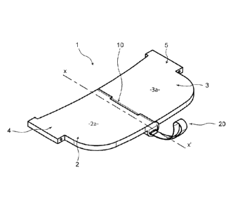
Figure 1 is a perspective view of a first embodiment of a foldable seat
according to the present invention in an unfolded position;
Figures 2a and 2b are, respectively, perspective views of the first and
second plates of the seat of Figure 1;
Figure 3 is a perspective view of the locking/unlocking system of the seat
of Figure 1;
Figure 4 is a top plan view, partially in cross-section along line C-C of
Figure 5, of the seat of Figure 1;
Figure 5 is a front view, partially in crbss-section along line B-B of Figure
4, of the seat of Figure 1;
Figure 6 is a side cross-section view along line A-A of Figure 4 of the
seat of Figure 1;
Figure 7 is a perspective view of the locking element used in the
locking/unlocking system of Figure 3;
Figure 8 is an underneath view of the locking element of Figure 7.
DETAILED DESCRIPTION OF EMBODIMENTS OF THE INVENTION
In reference to Figure 1, a foldable seat conform to the present invention
is shown.
The seat 1 comprises a first plate 2 defining an upper plane surface 2a,
said upper surface 2a having an approximately rectangular form, and a second
plate 3 defining an upper plane surface 3a, said upper surface 3a being
approximately symmetric to said upper surface 2a with respect to a vertical
plane passing through a longitudinal axis XX', said first and second plates 2,
3
CA 02779821 2012-06-14
-6-
being pivotally interconnected around said longitudinal axis XX' by a hinge
10.
Said first and second plates 2, 3 are also configured so as to be pivotally
connectable at their lateral free ends 4, 5 to a frame of a rollator or a
wheelchair. In particular, said lateral ends 4, 5 will be advantageously
configured so as to receive connecting means for pivotally connecting said
first
and second plates 2, 3 to said frame. Said plates 2 and 3 are made of a rigid
material, preferably in plastics or metal. In the position shown in Figure 1,
the
seat us locked in its unfolded position of use, in which the plane surfaces 2a
and 3a of said plates 2 and 3 are approximately aligned. In a further position
of
the seat, not shown, said plates 2 and 3 may be positioned in a folded
position,
in which their plane surfaces 2a and 3a define an angle less than 1800, and,
preferably, an angle approximately equal to zero. So as to lock or unlock said
plates 2 and 3 in said unfolded and/or folded position, the seat 1 comprises a
locking/unlocking system 20, illustrated in greater detail in Figure 3.
The hinge 10 is illustrated in greater detail in Figure 2. Said hinge 10
comprises a first cylinder 11 integral with the first plate 2, a second
cylinder 12
integral with the second plate 3 and a third cylinder 13 integral with the
first
plate 2, said first, second and third cylinders being coaxially aligned along
the
longitudinal axis XX', said second cylinder 12 being disposed between said
first
and said third cylinders 11, 13 and being rotatably movable with respect to
said
first and said third cylinders 11, 13 by means of a pivot pin 14, illustrated
in
Figure 4 or 6, extending along said longitudinal axis XX' through axial
through-
bores 11c, 12c and 13c of said first, second and third cylinders respectively.
In
the embodiment shown, the first plate 2 projects over said first and third
cylinders 11, 13 so that the proximal end 11a of said first cylinder 11 is
approximately aligned with the front side 2f of said first plate 2 and the
distal
end 13b of said third cylinder 13 is approximately aligned with the back side
2g
of said first plate 2. Furthermore, the second plate 3 projects over said
second
cylinder 12 so that, in the position of use of the seat 1, the proximal end
12a of
said second cylinder 12 is adjacent to the distal end 11b of said first
cylinder 11
and the distal end 12b of said second cylinder 12 is adjacent to the proximal
end 13a of said third cylinder 13 and so that, in said position of use of the
seat
CA 02779821 2012-06-14
-7-
1, the front side 2f, respectively the back side 2g, of said first plate 2 is
approximately aligned with the front side 3f, respectively the back side 3g,
of
said second plate 3.
In a second embodiment (not shown) of the invention, the hinge 10
differs from the first embodiment shown on Figures 2a and 2b by the fact that
it
comprises only two cylinders, a first one 11 integral with the first plate 2
and a
second one 12 integral with the second plate 3. In this embodiment, the first
and
second cylinders 11, 12 could advantageously be disposed so that the distal
end 12b of said second cylinder 12 is approximately aligned with the back side
3g of the second plate 3 and/or so that said first and second cylinders 11, 12
have approximately the same length.
In a third embodiment (not shown) of the invention, the hinge could also
comprise more than three cylinders. In this case, the locking/unlocking system
of the seat may advantageously be lodged at least partially inside at least
one
cylinder of said hinge, so that the unlocking element(s) of said
locking/unlocking
system is positioned at the periphery of the seat and/or at the exterior of
the
seat.
In reference to Figure 3, a locking/unlocking system conform to the
present invention is shown.
Said locking/unlocking system 20 comprises a locking element 21 and
two unlocking elements, i.e. a button 24 and a strap 25. However, in a further
embodiment (not shown) of the invention, said locking/unlock system 20 may
comprise only one unlocking element chosen among said button 24 and said
strap 25.
The locking/unlocking system 20 is advantageously configured so as to
be at least partially lodged inside said hinge 10, so that, in the unfolded
position
of use of the seat 1, the distal end 24b of said button 24 is approximately
aligned with the distal end 13b of the third cylinder 13, as shown in Figure
6, or
slightly recessed inside the hinge 20 at said distal end 13b of said third
cylinder
13, and the strap 25 extends at least partially outside of the first cylinder
11
from its proximal end 11a, as shown in Figure 4 and 6. Thus, said unlocking
elements 24 and 25 may be easily actuated by the hand of the user, either by
CA 02779821 2012-06-14
-8-
pushing said button 24 along the axial direction XX' or by pulling said strap
25
along the axial direction XX', both actions moving the locking element 21
along
the longitudinal axis XX' in the direction going from the back, or distal,
side of
the seat 1 to the front, or proximal, side of the seat 1. As explained in
detail in
the following description, this axial motion of the locking element 21
disconnects
the second cylinder 12 from the first cylinder 11 and permits a relative
rotational
movement between said cylinders 11, 12. In addition, said configuration avoids
an unwanted unlock of the seat 1, in particular in its unfolded position, due
to
the hidden position of the button 24 inside the hinge 10, which avoids an
unwanted actuation of said button 24.
As shown in detail in Figures 7 and 8, the locking element 21 has an
approximately cylindrical form. It comprises an axial through-bore 21c adapted
to receive one end of the pivot pin 14. Said end is fixedly connected to said
locking element 21 by means of a screw 32 received in corresponding threaded
holes formed in said pivot pin 14 and said locking element 21. The threaded
hole 30 formed in said locking element 21 leads to a first longitudinal
axially-
oriented groove 29 in which one end of the strap 25 is received, said end
being
fixedly connected to the locking element 21 by means of the same screw 32.
Several indentations 31 are advantageously formed in the external cylindrical
surface of the locking element 21 so as to lodge dirt or debris during use. A
second longitudinal axially-oriented groove 28 is also formed in said external
surface, said groove 28 being designed to mate with a projecting shape 18
formed in the internal cylindrical surface of an axial aperture 11c formed at
the
distal end 11 b of said first cylinder 11, thus permitting a sliding axially-
oriented
relative motion of said locking element 21 with respect to said first cylinder
11
and rendering said locking element 21 integral in rotation with said first
cylinder
11. At its distal end 21b, said locking element 21 comprises a projecting
shape
23 which is designed to mate with a corresponding notch 17i or 17j, see in
particular Figures 2b and 4, formed in the proximal end 12a of the second
cylinder 12, thus rendering said locking element 21 integral in rotation with
said
second cylinder 12 and locking said seat in its unfolded position or folded
position. In particular, when the seat 1 is in its locked unfolded,
respectively
CA 02779821 2012-06-14
-9-
folded, position, said projecting shape 23 abuts against the bottom of the
notch
17i, respectively 17j, and the upper end 23a and lower end 23b of said
projecting shape 23 is very close to the upper side and lower side of said
notch
17i, respectively the lower side and upper side of said notch 17j. In the
embodiment shown, said notches 17i and 17j are separated by the axial
through-bore 12c of the second cylinder 12 and are approximately symmetrical
with regard to the longitudinal axis of said second cylinder 12, corresponding
to
the longitudinal axis XX' in the position of use of the seat. In this
configuration,
the plane surfaces 2a and 3a of said first plates 2 and 3 define an angle
approximately equal to zero when the seat 1 is in its locked folded position.
However, in a further embodiment (not shown) of the invention, said plane
surfaces 2a and 3a may define an angle higher to zero, but less than 1800, in
the locked folded position of the seat when said notch 27j is not symmetrical
to
said notch 27i with regard to the longitudinal axis of said second cylinder
12. In
addition, in the embodiment shown, said notch 27j is deeper than said notch
271. In this configuration, the distal end 24b of the button 24 will be
positioned,
in the locked folded position of the seat, slightly outside of the hinge 20 at
the
distal end 13b of the third cylinder 13 so as to ease the accessibility to
said
button 24. However, in further embodiments (not shown) of the invention, said
notch 27j may have the same depth as said notch 271, or may be less deep than
said notch 27i, or, finally, only one notch 271 or 27j is formed in the
proximal end
12a of the second cylinder 12. In this last configuration, the seat 1 could
only be
locked in one position, i.e. an unfolded one or a folded one. In a further
embodiment (not shown) of the invention, said notch 27i and/or 27j may be
formed in the distal end 21b of the locking element 21 and the corresponding
projecting shape 23 may be formed in the proximal end 12a of the second
cylinder 12. In a preferred configuration of said embodiment, the positions of
said projecting shape 23 and said notch 27i and/or 27j may be symmetrical to
their positions in the embodiment illustrated in Figures 1 to 8 with regard to
a
plane perpendicular to the longitudinal axis XX'.
As shown in detail in Figures 4 to 6, the locking element 21 is lodged at
least partially inside an axial aperture 11c formed at the distal end lib of
the
CA 02779821 2012-06-14
-10-
first cylinder 11, said distal end lib being adjacent to the proximal end 12a
of
the second cylinder 12. In the configuration shown, said axial aperture 11c
corresponds to an axial through-bore of said first cylinder 11, said axial
through-
bore being closed at the proximal end 11 a of said first cylinder 11 by a lid
26
fixedly connected to said first cylinder 11. Said locking element 21 is urged
against the proximal end 12a of the second cylinder 12 by a spring means 22.
In the configuration shown, the spring means consists in a compression spring
22 lodged inside said axial aperture 11c, the ends of said spring 22 abutting
against the proximal end 21a of said locking element 21 and the internal side
of
said lid 26. As shown in Figure 3, said lid 26 includes a slot 27 through
which
the strap 26 may extend. So as to fixedly connect the button 24 to the pivot
pin
14, the distal end 14b of said pivot pin 14 may be advantageously screwed
inside a threaded hole formed in the proximal end 24a of said button 24. In
the
configuration shown in Figure 6, said button 24 is received inside an axial
aperture 16 formed at the distal end of an intermediate cylinder 15 lodged
inside
the hinge 10 and extending partially through an axial through-bore 13c of the
third cylinder 13 and an axial through-bore 12c of the second cylinder 12,
said
axial through-bore 12c having a narrower proximal end 12c1 adapted to receive
the pivot pin 14. The bottom of said aperture 16 forms a stop against which
said
button 14 abuts, thus limiting the axial motion of the locking element 21 and
avoiding that the projecting shape 18 is positioned outside of the groove 28.
In a
further embodiment (not shown) of the invention, said button 24 may also be
received inside an axial aperture formed at a distal end 13b of said third
cylinder
13, the bottom of said aperture forming also a stop against which said button
14
abuts.
The above detailed configuration of the first embodiment of the invention
illustrated in Figures 1 to 8 could easily be adapted to the above mentioned
second and third embodiments of the invention. In particular, the
configuration
illustrated in Figure 6 could easily be adapted to the second embodiment by
cancelling the separation between the second and the third cylinders and by
designating this combined cylinder as the second cylinder 12. In the same way,
the configuration in Figure 6 could easily be adapted to the third embodiment
by
CA 02779821 2012-06-14
-11-
adding further separations in the second and/or third cylinders and by
designating the cylinder inside which is lodged the button as the third
cylinder
and the cylinder inside which is formed the notches as the second cylinder.