Note: Descriptions are shown in the official language in which they were submitted.
CA 02779826 2016-02-03
WO 2011/057150
PCT/US2010/055733
MICROFIBROUS MEDIA FOR OPTIMIZING AND CONTROLLING HIGHLY
EXOTHERMIC AND HIGHLY ENDOTHERMIC REACTIONS/PROCESSES
15
CROSS-REFERENCE TO RELATED APPLICATION(S)
(Not Applicable)
FIELD OF THE INVENTION
The invention relates to a packed vessel that is able to be used to carry out
highly
exothermic or highly endothermic reactions or processes that utilize fine
temperature control.
The present invention relates to the processes which use the packed vessel to
carry out the
reactions and processes mentioned herein.
- 1 -
WO 2011/057150
PCT/US2010/055733
:A 02779826 2012 05 03
BACKGROUND OF THE INVENTION
Exothermic reactions and processes such as Fischer-Tropsch, and methanol
formation
from syngas, ethylene oxidation, maleic anhydride, phthalic anhydride,
formaldehyde,
acrylonitrile, acrylic acid, 1,2-dichloroethane, vinyl chloride, air
compression, concentrated acid
dilution, vapor condensation and others are strongly exothermic. Endothermic
reactions and
processes such as steam methane reforming and evaporation and others are
strongly
endothermic. Efficient heat transfer from/to reaction zone is required to
improve the product
selectivity, catalyst life and operational safety. A well-known reactor, the
multi-tube reactor in a
tube-and-shell configuration, has been used for highly exothermic or highly
endothermic
reactions. It is similar to a tube-and-shell heat exchanger, as shown in
European patent No.
0,308,034. It consists of a number of thin tubes (usually less than 2 inches)
in which catalyst
particles are filled. These tubes are surrounded by cooling fluids, which pass
through the shell
side of the heat-exchanger-like reactor. Due to the high surface to volume
ratio of the thin tubes,
efficient heat exchange is able to be achieved. However, this design faced
severe scale-up issues.
At a larger scale, more thin tubes are required. The increasing part count
makes the manufacture
of such types of reactors very difficult and expensive, especially at large
scales.
There were reactor designs that allow heating or cooling fluids passing
through the tube
side, and catalyst particles filled within space between shell and tubes.
These designs are able to
simply solve the scale-up issue of multi-tubular reactors, however, at the
cost of heat exchanging
efficiency. In this design family, different types of geometries of tubes have
been used to
improve heat exchanging efficiency, as shown in previous patents GB 2,204,055,
US 4,224,983,
US 5,080,872; different flow directions were also chosen for better heat
exchanging
performance.
These reactor designs, no matter how different they look, share one common
structural
characteristic: the reaction zone and heat exchanging zone are separated by
tube walls.
Therefore, these reactors are able to be classified as reactors with external
heat exchanging.
Several new catalyst/reactor structure designs have been developed to improve
the intra-
bed heat transfer. The first approach is wash-coated monolithic catalyst
structure, including
-2-
WO 2011/057150
PCT/US2010/055733
:A 02779826 2012 05 03
metal honeycomb structure (US 3,849,076; 4,101,287; 4,300,956; 6,869,578),
metal monolith
extrusion structure (US 6,881,703; 7,608,344) and metal microchannel reactor
(US 7,084,180;
7,226,574; 7,294,734). This approach wash-coats a thin layer of catalyst on
the internal wall of
the monolithic structures. These structures made of thermal conductive
materials (mainly metals
or metal alloys) transfer heat fast from/to the reaction zone. Some of the
catalyst structures have
thick channel walls that allow heat exchanged on their external surfaces. For
example, a catalyst
structure (US 7,608,344) is made by extrudating copper powders and then
structure is formed by
sintering or annealing in reducing environments. Copper forms a continuous
phase that provides
a very high thermal conductivity (e.g. 200 W/K-m), which equals to the product
of bulk copper
thermal conductivity and copper volumetric fraction (G. Groppi and E.
Tronconi). The copper
honeycomb structure transfers the heat from the wash-coated catalyst inside
channel walls to the
external honeycomb surface in an efficient way. Other monolithic or channel
structures (US
3,849,076; 4,101,287; 4,300,956; 6,869,578, 7,084,180; 7,226,574; 7,294,734)
have thin channel
walls and small channel sizes (usually several millimeters or less). In these
cases, some channels
have hot fluid and cold fluid passing through different channels next or cross
to each other using
the thin walls to separate the fluids and transfer heat. This design minimizes
the heat transfer
distance (resistance) and provides superior heat transfer performance at the
cost of reactor
complexity and reliability. In a word, the wash-coated monolithic structures
significantly
improve the heat transfer by reducing the heat transfer resistance and
increasing the heat
exchanging area. However, this wash-coated monolith approach, due to the
nature of wash-
coating, only allows a thin film of catalyst loaded inside the reactor
channel. A typical catalyst
volume loading is much less than 3 vol.%; some monolithic structures with
small channel size
(e.g. less than 1 mm) are able to reach a catalyst loading of 3-8 vol.%.
Moreover, the mass
transfer only take place by molecular diffusion in radial direction, which is
much slower than the
mass transfer in typical packed bed where bulk gas diffusion is dominant. The
limited catalyst
loading and low mass transfer rate results in slow reaction kinetics.
Another approach uses metal microfibrous media with catalyst entrapped for
fast heat
transfer. This type of media was first developed by Tatarchuk in 1992 (US.
5,080,963,
-3-
:A 02779826 2012 05 03
WO 2011/057150
PCT/US2010/055733
5,096,663). The media had good electrical conductivity and was developed as
electrode materials
for supercapacitors and fuel cells. Due to the similarity, the thermal
conductivity of the materials
should be predictable. Since 1994, this media has been modified for catalytic
processes (US
5,102,745, 5,304,330, 6231792, 7,501,012) and sorbent processes. In 2001, a
novel reactor
design with a folded microfibrous media sheet, which was parallel to the flow
direction was
proposed for fast heat transfer. This design also suffers from the slow radial
molecular diffusion
limit due to its parallel flow pattern. Moreover, the porous media only take
negligible amount of
reactor volume. Considering the low volume fraction of catalyst in this
microfibrous media, the
overall catalyst loading in the reactor will be extremely low. The folded
structure has only
several edge contacts with the reactor wall for heat transfer. This means the
effective heat
exchanging area is very limited. These drawbacks make the design much less
competitive
compared to the monolithic approach.
SUMMARY OF THE INVENTION
A microfibrous media made of micro-sized highly conductive fibers, which is
able to
entrap various catalyst material inside and form microfibrous entrapped
catalyst, is a general
catalyst carrier with enhanced intra-bed heat transfer characteristics. A
sorbent or an
electrocatalyst is able to be entrapped within the microfibrous media instead
of the catalyst.
Microfibrous entrapped catalysts demonstrated more than 45 times higher
thermal conductivity
and more than 10 times higher heat transfer co-efficient than a traditional
packed bed due to the
use of highly conductive micron-sized metal fibers made of copper, silver,
aluminum, nickel, and
others, and improved wall contacting. Because microfibrous media entraps fine
catalyst
particles, the microfibrous entrapped catalysts demonstrated similar reaction
rate at a much lower
catalyst loading than the traditional packed bed. By changing the active
entrapped catalyst,
microfibrous media is able to be applied to different highly exothermic and
highly endothermic
reactions/processes, and reactions/processes that utilize fine temperature
control or uniform
temperature profile.
-4-
WO 2011/057150
PCT/US2010/055733
:A 02779826 2012 05 03
BRIEF DESCRIPTION OF THE DRAWINGS
FIG. 1 illustrates a photo of a microfibrous media and microfibrous entrapped
catalysts
according to some embodiments.
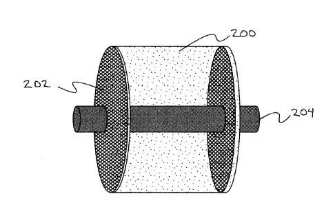
FIG. 2 illustrates a diagram of an example of a microfibrous media assembly
according to
some embodiments.
FIG. 3 illustrates a graph of the effectiveness factor versus catalyst
particle radius
according to some embodiments.
FIG. 4 illustrates a graph of thermal conductivity measured for microfibrous
media made
of stainless steel at various metal fiber volume fractions according to some
embodiments.
FIG. 5 illustrates a diagram of a test apparatus to verify the improvement in
thermal
conductivity using metal microfibrous entrapped catalyst according to some
embodiments.
FIG. 6 illustrates a graph of transient performance of using microfibrous
entrapped
catalyst to improve thermal conductivity according to some embodiments.
FIG. 7 illustrates a graph of measured effective thermal conductivity in
transient tests
according to some embodiments.
FIG. 8 illustrates a graph of a measure of effective thermal conductivity in
steady state
tests according to some embodiments.
DETAILED DESCRIPTION OF THE PREFERRED EMBODIMENT
The present invention focuses on improving the intra-bed heat exchanging
efficiency and
maintaining high catalyst, sorbent or electrocatalyst loading. In some
aspects, catalysts, sorbents
and electrocatalysts are all referred to generically as thermal facilitators.
Although catalysts are
typically described herein, in some embodiments, sorbents and/or
electrocatalysts are used in
addition to or instead of catalysts. The invention employs microfibrous media
made of micro-
sized fibers of high thermal conductivity to transfer heat. The media is
inserted into the reaction
zone under physical compression. Due to the compression and its flexibility,
the media well
touches the reactor internal wall and utilizes the entire reactor internal
wall for heat exchanging.
More importantly, the metal microfibrous network made of highly conductive
metals, where
-5-
WO 2011/057150
PCT/US2010/055733
:A 02779826 2012 05 03
catalytic materials are entrapped, provides fast paths to transfer heat from
catalyst particles to the
reactor wall in case of exothermic reaction. The fluid perpendicularly or near-
perpendicularly
passes through the microfibrous media. This flow direction enables accelerated
heat and mass
transfer due to bulk diffusion. As a result, this catalyst structure is able
to provide enhanced mass
transfer rate, high activity catalyst loading, large heat exchanging area and
low heat transfer
resistance.
The present invention is able to be referred to as a reactor with optimized
intra-bed heat
exchanging. The invention is able to be combined with the reactors with
external heat
exchanging for the ultimate heat exchanging performance. In the invention, the
highly
exothermic or highly endothermic reactions take place on the catalysts
particles entrapped within
the microfibrous network, or the reactions take place on the surface of metal
fibers. The
microfibrous entrapped catalysts are loaded in the reactors for highly
exothermic and high
endothermic reactions. The microfibrous entrapped catalysts are flexible; they
are able to match
the shape of reactor and contact with the metal reactor wall very well.
Moreover, the metal fibers
are typically made of highly thermally conductive metals such as silver, zinc,
copper, aluminum
and other metals. Thus the metal fibers behave as a bridge that transfers the
heat generated from
the catalysts particles, where reaction takes place, to a cold reactor wall
for highly exothermic
reactions; and transfer the heat from the hot reactor wall to catalyst
particles or metal fibers for
highly endothermic reactions. The present invention is able to also be applied
for a process that
requires fine temperature control or uniform temperature profile. Due to the
use of highly
conductive metals, the microfibrous media has a near-isothermal temperature
profile, as
illustrated in examples below.
The present invention is able to work with the current reactors with improved
external
heat exchanging for the best heat exchanging performance. Microfibrous
entrapped catalysts are
able to be loaded either in the tube side or the shell side. If in the tube
side, the microfibrous
entrapped catalyst media is able to be loaded in the tubes in the form of
disk, rod or another
form. The tube diameter is able to be much larger than these in traditional
multi-tubular reactors
due to significantly improved heat exchanging rate. Thus the part counts are
able to be
-6-
WO 2011/057150
PCT/US2010/055733
:A 02779826 2012 05 03
significantly reduced, and the manufacturing reactor for large scales will be
much cheaper and
easier than traditional multi-tubular reactor approach. Similarly, metal
microfibrous entrapped
catalyst is able to also be loaded in shell side in form of disk, pellets,
rolls, and other forms.
In order to maintain the optimized contact between microfibrous media and
facilitate the
loading/uploading into/from the reactor, a microfibrous media assembly is
invented. It includes
supporting structures (e.g. plates and screens) and the microfibrous media in
between. The
supporting structures integrate many tiny microfibrous media pieces into a
single article, which
is easy to load or unload. The structures hold and compress the media, make it
uniformly
distributed and compressed inside the reactor and well attached to the reactor
wall. In some
cases, the supported structure also helps to disperse and even take the force
on the entire
microfibrous media bed due to pressure drop.
It is an object of the subject invention to provide a superior heat transfer
from/to gaseous
or liquid streams. For this object, highly conductive metal fibers are used to
prepare microfibrous
entrapped catalysts. These fibers are made of metal or metal alloys with high
thermal
conductivities, such as copper, silver, aluminum, nickel and their alloys. For
particular
conditions involving corrosion, micro-sized fiber of special metals or metal
alloys (e.g. stainless
steel) with lower thermal conductivity will be used. The fiber volume contents
are able to be
tailored to achieve the optimal heat transfer performance as well as catalytic
activity,
microfibrous structure integrity, pressure drop, and other characteristics.
The microfibrous media are formed from fibers, with such fibers generally
having a
diameter of at least 1 micron with the fibers having a diameter which
generally does not exceed
32 microns, although smaller or larger diameters are able to be used. A
typical fiber volumetric
fraction is in the range of 1-10 vol .%. Higher volume fractions are able to
also be achieved to
enhance the heat transfer for special cases.
The active catalytic materials are able to be catalysts particles, or
microfibrous network
made of special metals, or coating on the microfibrous network. The catalysts
particles are in the
form of grains, pellets, extrudates, rings, combinations thereof or others
forms. The typical
particle size is in the range of 10 microns to 300 microns (0.3 millimeter),
although smaller or
-7-
WO 2011/057150
PCT/US2010/055733
:A 02779826 2012 05 03
larger particles are also able to be used. A typical particle volumetric
fraction is in the range of
0-20 vol.%. However, higher particle volume fractions are also able to be
used.
It is to be understood that the microfibrous entrapped catalysts are able to
be comprised
of one type of fiber or are able to be comprised of two or more different
fibers and the metal
fibers are able to have a single diameter or are able to have different
diameters. Additionally, the
fibers are able to be coated with a thin film of catalyst whereby the mesh
support is coated with
catalyst in addition to having catalyst fibers or particles retained in
interstices of the mesh
support.
It is an object of the invention to provide a reaction rate, if not greater
than, comparable
to that of a traditional packed bed made of pellets or extrudates. In this
invention, small catalysts
particulates (10-300 micron) are entrapped in the metal microfibrous network.
These particulates
are too small to fill in a traditional packed bed. Due to the high external
surface area and
minimized pore diffusion achieved at small particle sizes, the microfibrous
entrapped catalysts
are able to reach a volumetric reaction rate that is slightly greater than a
traditional packed bed,
as shown in the examples below.
The present invention provides a general platform to entrap various catalysts
for different
reactions. It is an object of this invention to provide a microfibrous support
structure for
retaining and entrapping particulate or fiber materials that are chemically
reactive toward a
predetermined reactant. The microfibrous entrapped catalysts are able to be
initially formed by
producing a microfibrous media having a catalyst support retained in the
interstices thereof,
followed by impregnating the retained support with an appropriate catalyst.
Alternatively, the
microfibrous media is able to be produced with supported or unsupported
catalyst particles in the
microfibrous network. Moreover, the microfibrous entrapped catalysts are able
to also be
produced wherein the particles retained therein are catalyst precursors, which
precursors are
subsequently converted to an active catalyst. As another alternative example,
the microfibrous
entrapped catalyst is able to be initially formed and the catalyst or catalyst
precursors inserted
into the interstices of the microfibrous network after formation of the
network.
-8-
CA 02779826 2016-02-03
WO 2011/057150
PCT/US2010/055733
The microfibrous entrapped catalysts with particles or fibers retained in the
interstices
thereof are preferably produced by a procedure of the type described in U.S.
Patents 5,304,330;
5,080,963; 5,102,745; or 5,096,663, and US Patent Applications 20020068026 and
20050169820. Traditional high speed and low cost paper making equipment and
techniques are
able to be used to prepare the composite material. In such a process, micron-
sized diameter
metal, polymer, glass, ceramic or other fibers in a variety of compositions
and alloys are able to
be slurried in an aqueous suspension (along with optional binders, if
required) and with the
possible use of cellulose fibers and other selected reactant or support
particulates such as, but not
limited to, alumina support particles. The resulting mixture is able to then
be cast into a
preformed sheet using a wet-lay process and dried to create a sheet of
preformed material. Where
a water soluble binder is used in this preparation, drying may be sufficient
to fuse the fibers at
their junctures, but in the case of those pre-forms utilizing cellulose,
subsequent pre-oxidation in
an 02 flow at approximately 500 C for generally about one hour may be
employed to remove
the bulk of cellulose. Subsequent sintering of the pre-form in an 112 flow at
an elevated
temperature (700-900 C, depending on the type of fiber) for generally about
thirty minutes
allows for removal of the remaining cellulosic binder/pore former and entraps
the selected
support particulates within a sinter-locked network of metal, glass or ceramic
fibers.
Figure 1 shows one type of microfibrous media made of copper for highly
exothermic
and highly endothermic reactions. Figure 2 describes an example of an assembly
of microfibrous
media to facilitate packing and unpacking, including a microfibrous media
stack (200), a flow
through mechanical layer (202) and a metal rod (204).
Figure 3 depicts the reactivity of using small particulates in a microfibrous
network for
Fischer-Tropsch synthesis. The reaction of Fischer-Tropsch synthesis (FTS) is
controlled by pore
diffusion. The small particulates of 100-200 micron in size demonstrated an
effectiveness factor
of approximately 1. The effectiveness factor of 3/16" extrudates widely used
in FTS is
approximately 0.2. Considering the catalyst fraction of the microfibrous
entrapped catalyst is
around 0.15, and the catalyst particle volumetric fraction is around 0.6, the
catalyst loading in the
packed bed is 4 times higher than that in the microfibrous entrapped catalyst.
As a result, the
- 9 -
CA 02779826 2016-02-03
WO 2011/057150
PCT/US2010/055733
reaction rate in the microfibrous entrapped catalyst will be 1.25 times higher
than that in the
typical packed bed. Similarly, if a reaction is controlled by external mass
transfer, the
microfibrous entrapped catalyst will provide an even higher reaction rate than
typical packed
beds due to large external surface area and fast external mass transfer rate.
These results suggest
the use of microfibrous entrapped catalyst will not hurt the reaction rate
even if the active
catalyst volumetric loading in microfibrous entrapped catalyst is only 1/4 of
that in a typical
packed bed. This results from the use of small sized particles, which have
high external surface
area and a high effectiveness factor.
Figure 4 demonstrates the measured thermal conductivity of several stainless
steel
microfibrous media with various microfiber volumetric fractions. The result
indicates that the
thermal conductivity of microfibrous media equals the product of thermal
conductivity of bulk
stainless steel and the volume fraction of stainless steel fibers. The result
suggests the thermal
conductivity of the microfibrous entrapped catalyst containing microfibers and
catalyst particles
is able to be calculated using a volumetric weighted average.
Figure 5 illustrates a test apparatus to experimentally verify the improvement
in thermal
conductivity of using microfibrous entrapped catalysts. It mainly includes a
stainless steel tube
and a water bath (300). The tube had an inner diameter of 1.4 inches and the
length is 8 inches.
Inside the tube, a fixed bed of test material (304) was loaded at the center
of the tube. Several
thin thermocouples were buried inside the fixed bed. Both ends of the tube
were tightly sealed,
preventing the water from contacting the test materials. Only a N2 stream
(302) is able to enter
the tube. The water bath (300) was maintained at ¨92 C.
A packed bed made of A1203 particles (60-80 mesh) and a layer of copper
microfiber
entrapped A1203 (60-80 mesh) were compared for heat transfer performance at
both steady state
and transient state. The packed bed was 2 inches long and with a thermal
capacity of 10.8 J/K
inch of bed. The microfibrous entrapped catalyst contained 5 vol.% copper
fibers, and 20% of
alumina. The layer of microfibrous entrapped catalyst was also 2 inches long
and its thermal
capacity is 10.9 J/K inch of bed. The two fixed beds have almost the same
thermal capacity, thus
all the differences in temperature changes during the test will result from
difference in their
- 10-
CA 02779826 2016-02-03
WO 2011/057150
PCT/US2010/055733
thermal conductivity. Other packed beds made of mixture of copper powder (60-
80 mesh) and
the A1203 particles, and micro fibrous media beds made of Ni fiber and
Stainless Steel fibers
were also evaluated.
Two sets of experiments were carried out using this test apparatus. The first
set of
experiments was carried out for transient state evaluation. During the tests,
the test tube was
immersed into the water bath (300) at time 0, and the temperatures read by the
thermocouple at
point "1" (306) were recorded every minute. The temperature time profiles of
the packed beds
and micro fibrous beds are shown in Figure 6. It is clear that copper micro
fibrous entrapped
catalyst reached 90 C in about 2 minutes. However, it took the packed bed
more than 18
minutes to reach the same temperature. Since the two beds had almost the same
thermal capacity,
the significant difference suggests that the copper microfibrous entrapped
catalyst has a much
higher thermal conductivity than the packed bed of alumina. The estimated
effective thermal
conductivities of these fixed beds are shown in Figure 7. Copper microfibrous
media
demonstrated a thermal conductivity of ¨10 W/K-m, which is 47 times higher
than those of the
packed bed made of particles, including the packed bed made of copper powders.
The media
made of Stainless Steel fibers, which has much lower thermal conductivity
compared to copper
fiber, also demonstrated a thermal conductivity 17 times higher than those of
the packed beds.
The second set of experiments evaluates the performance of the two beds at
steady state. During
the experiments, the tube with a fixed bed loaded was immersed into the water
bath. A N2 flow at
18 SLPM was passed through the reactor. The temperatures read by a different
thermocouple
reached steady state in about 30 minutes. Then the temperatures were recorded
every 30 minutes
for 2 hours. The temperature at the center-line of the fixed beds is shown in
Figure 8. It is clear
that the gas temperature increased very quickly from 40 C at entrance to near
the water batch
temperature of 80 C at the center point (x/L=0.5) of the microfibrous bed.
The temperature
increase in the case of the AI203 packed bed is only 4 C. The temperature
increase of the
microfibrous entrapped catalyst is 10 fold higher than that of the packed bed.
This suggests metal
microfibrous entrapped catalyst has high heat transfer coefficient to transfer
the heat from the
reactor wall to the stream flowing through the reactor. The averaged heat
transfer
-11-
WO 2011/057150 A02779826 2012 05 03
PCT/US2010/055733
coefficient of the microfibrous entrapped catalyst is approximately 10 times
higher than that of
the packed bed. This will significantly benefit highly endothermic reactions,
in which a huge
amount of heat is required to be transferred into the bed, especially the
center, to sustain the
reaction. Microfibrous entrapped catalysts will also benefit highly exothermic
reactions, in which
a huge amount of heat needs to be removed from the bed, especially the center,
to keep the
reactions under control.
A packed bed made of Co/A1203 catalyst and microfiber media with the same
catalyst
entrapped were evaluated for Fischer-Tropsch synthesis in a 3/4" stainless
steel reactor (15 mm
id). The experimental conditions are listed in Table 1. Both beds had a volume
of 15.7 cc and
contained catalyst of 2.5 g (20 vol.% catalyst loading). The packed bed was
diluted by A1203
particles. The center-line temperature profile was measured by multipoint
thermocouple and is
shown in Table 2. The packed bed experiment was carried out at 225 C and
achieved a CO
conversion of 0.54. In order to maintain the same conversion, the reactor wall
temperature of the
microfiber media bed had to be maintained at 235 C. The centerline
temperatures of the packed
bed were 3-6 times higher than the temperatures in the microfibrous media bed.
The
microfibrous media bed reached a maximum temperature gradient of 2.1 C. If
the heat transfer
via thermocouples is taken into consideration, actual temperature gradient
inside the packed bed
is higher than the measured results. For a FTS reactor with larger diameter,
i.e. 2", the
temperature gradient will be higher than 30 C in the packed bed, 10 C in the
microfibrous
media bed, according to a conservative estimation. The uniform temperature
profile in a
microfibrous bed will provide an improved selectivity to desired product. If
30 C is tolerable,
then the microfibrous bed is able to be of a larger diameter thus
significantly reducing the
required tube numbers to reach the same productivity. Moreover, the
microfibrous media bed
only utilizes 1/4 of catalyst loaded in typical packed bed, as discussed
before. As a result, the
reactor construction cost will be significantly reduced due to lower part
count and less catalyst
loading.
-12-
WO 2011/057150
PCT/US2010/055733
:A 02779826 2012 05 03
Packed Bed Copper MFEC
flow rate/h4 830.4 830.4
Wall T/ C 225 235
Conversion 0.543 0.538
Table 1. Temperature profile along FTS reactors with a single pass conversion
of 0.54.
Point Location T/ C T-Twall/ C T/ C T-
Twall/ C
Gas 1 216.4 -8.6 226.5 -8.5
Heat 2 219.6 -5.4 228.5 -6.5
Up 3 222.6 -2.4 232.2 -2.8
,
4 228.7 3.7 234.9 -0.1
-13-
WO 2011/057150
PCT/US2010/055733
:A 02779826 2012 05 03
Reaction 5 231.9 6.9 237.1 2.1
Section 6 229.5 4.5 235.8 0.8
Average 4-6 230.03 5.03 235.93 0.93
Table 2. Temperature profiles inside the FTS reactor.
To utilize the microfibrous media, the microfibrous media is used in a desired
implementation such as a container for a sorption process, a container for a
catalytic reaction
process, a component in a high efficiency heat exchanger, a thermal sink or
phase change
thermal modulator, part of an electrochemcial reactor or a static mixture.
Depending on the
implementation, the microfibrous media is used accordingly. Common to the
implementations is
the improved thermal conductivity and heat transfer.
In operation, the microfibrous media enhances intra-bed heat transfer
characteristics.
Microfibrous entrapped catalysts have a much higher thermal conductivity and a
higher heat
transfer co-efficient than a traditional packed bed due to the use of highly
conductive micron-
sized metal fibers and improved wall contacting. Since microfibrous media
entraps fine catalyst
particles, the microfibrous entrapped catalysts have a similar reaction rate
at a much lower
catalyst loading than the traditional packed bed. By changing the active
entrapped catalyst,
microfibrous media is able to be applied to different highly exothermic and
highly endothermic
reactions/processes, and reactions/processes that utilize fine temperature
control or uniform
temperature profile.
-14-
WO 2011/057150
PCT/US2010/055733
:A 02779826 2012 05 03
Some embodiments of the invention are described herein.
In some embodiments, an internal packing that enhances external transport into
or out of
a vessel. The packing promotes heat transfer. The packing promotes electrical
conduction. The
packing is malleable to promote good internal contacting to itself and to the
internal walls of the
vessel. The vessel is sealed. The vessel is a flow through design, or
periodically opened, closed,
or the flow is variable in flow rate or direction. The vessel is tubular,
rectangular, conical or of
some other cross-sectional description or form factor. The vessel serves as a
container for a
sorption process. The vessel serves as a container for a catalytic reaction
process. The vessel
serves as a component in a high efficiency heat exchanger. The vessel serves
as a thermal sink
or phase change thermal moderator. The vessel is part of an electrochemical
reactor. The vessel
serves as a static mixer. The packing includes high thermal conductivity
fibers. The packing
includes fibers with high electrical conductivity. The fibers are used to
immobilize a sorbent.
The fibers are used to immobilize a catalyst. The fibers are used to
immobilize an
electrocatalyst. The fibers are used to infiltrate a phase change medium. The
fibers are fused at
their junctures to promote heat transfer or electrical conduction. The
dimensions of the fibers
and immobilized phase are chosen to minimize pressure drop. The dimensions of
the fibers and
immobilized phase are chosen to promote high levels of volumetric reactivity.
The fiber
diameter and composition are selected to promote high levels of heat transfer
at the inside wall of
the vessel. The fiber diameter and composition are selected to promote high
levels of electrical
conduction and low contact resistance at the inside wall of the vessel. The
orientation of the
packing is selected to promote heat transfer or electrical conduction in a
specific direction. The
volume fractions of the conduction aid and the immobilized phase are
adjustable over wide
ranges. The fibers are of different diameters. The packing and entrapped phase
are spatially
graded. The diameter, volume loading and composition of the fibers and the
immobilized phase
are optimized to promote the rate of reaction and/or sorption per unit of
pressure drop. The
diameter, volume loading and composition of the fibers and the immobilized
phase are optimized
to minimize the intravessel temperature gradient within the reaction and/or
sorption vessel at a
-15-
WO 2011/057150
PCT/US2010/055733
:A 02779826 2012 05 03
specified level of volumetric reactivity. The diameter of the fibers and
immobilized phase are
optimized to promote the rate of electrochemical reaction per unit of
electrical resistance. The
diameter, volume loading and composition of the fibers and immobilized phase
are optimized to
minimize the intravessel electrical resistance at a specified level of
volumetric reactivity. The
medium in the vessel in contact with the packing is a gas. The medium in the
vessel in contact
with the packing is a liquid. The medium in the vessel in contact with the
packing is a two phase
mixture of liquid and gas. The medium in the vessel in contact with the
packing undergoes a
phase change. The process occurring is exothermic or endothermic. The rate of
the process
occurring in the vessel depends on temperature. The selectivity of the process
occurring in the
vessel depends on temperature. The internal packing helps remove exotherms or
endotherms
associated with sorption, desorption, or steady-state catalytic or
electrochemical reaction. The
packing helps remove heat and reduce thermal excursions associated with
nonsteady-state
heterogeneous reactions such as catalyst regeneration, calcinations,
oxidations and
autoreductions. The intrapacking Reynold's number is low and lies in a regime
of non-turbulent
flow. The intrapacking Reynold's number is high and lies in a regime of
turbulent flow. The
volume fraction of catalyst, sorbent or electro catalyst is higher than that
which can be attained in
a fixed bed reactor of a packed bed or monolithic design. The level of
reaction and heat transfer
are similar to a fluid bed reactor but in the absence of back mixing. The
position of the
immobilized solid reactive phase does not depend on gravitational orientation
or fluid velocity
versus particulate drag forces. The volume fraction and diameter of the fibers
are selected to
entrap solids of a selected particle size. The vessel permits higher levels of
chemical conversion
per pass or per cycle. The vessel permits higher levels of chemical conversion
per pass with the
lowest possible temperature gradient within the internal packing. The packing
is stacked or
layered onto an assembly apparatus to facilitate packing, unpacking or
maintenance of the vessel.
Intermediate inert mechanical layers are used to maintain the malleable
packing at a selected
volume fraction and mechanical loading. Layers of the packing material are
stacked in a specific
order to promote process integration and process intensification. The profile
and cut patterns
within the layers are selected to promote fluid contacting, mixing and
prescribed fluid movement
-16-
WO 2011/057150
PCT/US2010/055733
:A 02779826 2012 05 03
within the internal packing. The structure of the apparatus is used to mount
various sensors such
as thermocouples, chemical sensors, flow sensors, pressure sensors and other
sensors. The
output of the sensors is used to control the process to promote: economics,
safety, environmental
compliance and process throughput per unit of: volume, mass or energy. An
apparatus includes
multiple vessels within a common manifold, and operated similar to a "tube"
and shell heat
exchanger. The vessels are not tubular but adhere to the specified form
factors. The heat is
transferred in a co-current fashion. The heat is transferred in a counter-
current fashion. The
number of individual vessels is reduced (at constant volume of the entrapped
media) by making
each vessel larger and still maintaining adequate thermal control due to the
enhanced
conductivity of the media. The individual vessels are not located within a
common manifold but
operate individually. The number of vessels is significantly reduced because
they can be made
of larger volume and still provide adequate heat transfer properties at a
fixed level of chemical
processing throughput. The vessels are made shorter in the axial flow
direction because heat is
transferred more effectively and temperature sensitive equilibrium limited
reactions occur to a
greater and more desirable degree. The performance attributes and compositions
of the catalyst,
electrocatalyst or sorbent are specifically selected in a non-obvious manner
to take advantage of
the enhanced transport properties and intra-media operating temperature
specific to the process
and assemblage network of the vessels.
In some embodiments, a microfibrous reactor for highly exothermic and highly
endothermic reactions/processes comprises a reactor tube packed with
microfibrous media made
of highly thermal conductive micron-sized fibers or assemblies made of the
microfibrous media.
A fluid perpendicularly or near-perpendicularly passes through the
microfibrous media inside the
reactor. The thermal conductive microfibrous media transfers the heat from the
fluid to the
reactor wall for exothermic reaction/processes, and from the reactor wall to
the fluid for
endothermic reaction/processes. The reactor tube is made of metal and other
thermal conductive
materials, which may be, but are not limited to, metals, metal alloys, C, Si,
SiC. The
microfibrous media comprises approximately 1-25 vol.% of micron-sized fibers
and 0-60vol.%
of catalyst or sorbent/adsorbent materials. The micron-sized fibers are fibers
made from metal
-17-
WO 2011/057150
PCT/US2010/055733
:A 02779826 2012 05 03
with high thermal conductivities. These metals may be, but are not limited to,
silver, copper,
aluminum, nickel, iron, titanium, chromium, and metal alloys of these metals.
The micron-sized
fibers are fibers made from non-metal materials with high thermal
conductivities. These
materials may be, but are not limited to, C, Si and SiC. The micron-sized
fibers have an average
diameter of about 1-30 microns, though fibers with larger diameters may also
be used. The
catalytic materials are entrapped catalyst particles, active coating layers on
the micron sized
fibers, and/or the active surface areas of the metal fibers themselves. The
sorbent/adsorbent
materials are entrapped sorbent/adsorbent particles, active coating layers on
the micron sized
fibers, and/or the metal fibers themselves. The catalyst particles and
sorbent/adsorbent particles
have an average diameter of 10-300 microns, though smaller or larger particles
may also be
used. The catalyst particles and sorbent/adsorbent particles are in the form
of powder, grains,
pellets, extrudates, rings, or combinations thereof. The microfibrous media is
in the form of a
stack (or stacks) of disks in reactors of axial flow direction, and rolls in
the reactors of radial
flow direction so that the flow direction is perpendicular or near-
perpendicular to layers of
microfibrous entrapped catalyst. Other shapes such as spheres, fussy pellets,
and other complex
three dimensional structures, or various combinations thereof may also be
used. The assembly of
microfibrous media includes microfibrous media in various shapes and
supporting structures.
The supporting structures hold and compress the microfibrous media to attach
the reactor wall,
and facilitate loading the microfibrous media into the reactor and unloading
the media out from
the reactor, especially when the reactor is long. The reactors packed with
microfibrous
entrapped catalysts provide improved heat transfer means for highly exothermic
and highly
endothermic reactions/processes, and reactions/processes that need fine
temperature control and
uniform temperature profile. The microfibrous entrapped catalysts transfer
heat (generated/ or
consumed) from the reaction/catalyst zone to the outer wall (in an e.g.,
tubular reactor), where
other heat transfer fluids or measures are employed to remove/add required
heat in order to
maintain an optimal reactor temperature and temperature profile for highly
selective and/or high
volume reactivity applications. The microfibrous entrapped catalysts transfer
heat to/from the
reaction zone, where endothermic/exothermic reactions take place. The
exothermic
-18-
WO 2011/057150
PCT/US2010/055733
:A 02779826 2012 05 03
reactions/processes include, but are not limited to, Fischer-Tropsch synthesis
for hydrocarbons,
methanation, methanol formation and other alcohol synthesis using carbon
monoxide and
hydrogen, gas-to-liquid (GTL), coal-to-liquid (CTL) processes, biomass-to-
liquid (BTL)
processes, hydrocarbon partial oxidation reactions, ammonia synthesis,
adsorption, air
compression, and others. The endothermic reactions/processes include, but are
not limited to,
steam reforming, and ammonia decomposition, reactor cooling and others. The
reactions/processes include both homogeneous and heterogeneous
reactions/processes. The fluid
is able to be gaseous and/or liquid. The structured catalyst material where
the volumetric loading
of either catalyst or metal fiber, or both, is spatially graded across the
cross-section or other
defining coordinate system so as to optimally adjust heat transport through
the fibers versus heat
generation/removal at the catalyst surface. The structured catalyst wherein
the fiber hardness,
media compressibility, fiber diameter, or other physical means are chosen to
increase the number
of fiber contacts at the interior wall of the reactor thereby increasing the
critical interior wall heat
transfer coefficient. A heterogeneous reactive structure wherein the catalyst
is replaced by a
chemical adsorbent or absorbent which is also used for either an endothermic
or exothermic
chemical separation process. A metal fiber entrapped chemical reactant which
is either
consumed or produced during the course of the reaction, is accommodated within
a conductive
metal fiber matrix so as to achieve appropriate and desired temperatures
during the course of the
chemical reaction. A general reactor design process and reactor wherein the
ratio of heat
generating/removing materials and reactions are balanced against the inclusion
and distribution
of conductive metal fibers so as to better optimize and improve the general
performance of the
process. The reactor design process wherein the goal of the optimization may
include on or
more of the following: lowest annualized operating cost, highest single pass
conversion, greatest
selectivity to a desired product, lowest selectivity to an undesired product,
smallest and/or
lightest reactor, smallest and lightest balance-of-plant (including the
summation of other process
units and unit operations) for a more complex process flow sheet that is
driven by both the
reactor performance itself as well as other required separations, recycle
streams, product
specifications and others. A structured reactive material wherein the number
of individual
-19-
WO 2011/057150
PCT/US2010/055733
:A 02779826 2012 05 03
reactor tubes can be significantly reduced because they can be made larger in
diameter (and still
maintain appropriate temperature control) due to the presence of the
conductive fibers. The
structured material wherein the metal fibers are replaced by other high
thermal conductivity
fibers including: polycrystalline diamond, graphites, diamond coated fibers,
silicon carbides,
sapphire, and other polymers, inorganics or composites and coatings thereof. A
generalized
methodology of improved chemical reaction process control that is accomplished
by one or more
temperature sensors, or chemical reactant/product composition sensors that are
embedded in a
reactive structure and which can utilize optimized feedback process control in
order to achieves
and realize various process optimization goals.
In some embodiments, an internal packing that enhances external transport out
of (or
into) a vessel comprises microfibrous media made of highly thermal conductive
micron-sized
fibers or assemblies made of the microfibrous media for exothermic (or
endothermic)
reactions/processes. A fluid perpendicularly or near-perpendicularly passes
through the internal
packing inside the vessel. The packing promotes heat transfer. The packing
promotes electrical
conduction. The packing is malleable to promote good internal contacting to
itself and to the
internal walls of the vessel. The vessel is sealed. The vessel is a flow
through design, or
periodically opened, closed, or the flow is variable in flow rate or
direction. The vessel is
tubular, rectangular, conical or of some other cross-sectional description or
form factor. The
vessel serves as a container for a sorption process. The vessel serves as a
container for a
catalytic reaction process. The vessel serves as a component in a high
efficiency heat exchanger.
The vessel serves as a thermal sink or phase change thermal moderator. The
vessel is part of an
electrochemical reactor. The vessel serves as a static mixer. The vessel is
made of metal and
other thermal conductive materials, which may be, but are not limited to,
metals, metal alloys, C,
Si, SiC and other ceramics. The microfibrous media comprises approximately 1-
25 vol.% of
micron-sized fibers and 0-60 vol.% of catalyst or sorbent/adsorbent materials
as immobilized
phase. The packing and entrapped phase are spatially graded. The micron-sized
fibers are fibers
made from metal with high thermal conductivities. These metals may be, but are
not limited to,
silver, copper, aluminum, nickel, iron, titanium, chromium, and metal alloys
of these metals.
-20-
WO 2011/057150
PCT/US2010/055733
:A 02779826 2012 05 03
The fibers made from non-metal materials with high thermal conductivities.
These materials may
be, but are not limited to C, Si, SiC, aluminum nitride and boron nitride. The
micron-sized fiber
are fibers with high electrical conductivity. The micron-sized fibers have an
average diameter of
about 1-30 microns, though fibers with larger diameters may also be used. The
micron-sized
fibers have different diameters. The fibers are fused at their junctures to
promote heat transfer or
electrical conduction. The catalytic materials include entrapped catalyst
particles, active coating
layers on the micron sized fibers, and/or the active surface areas of the
metal fibers themselves.
The sorbent/adsorbent materials include entrapped sorbent/adsorbent particles,
active coating
layers on the micron sized fibers, and/or the metal fibers themselves. The
catalyst particles and
sorbent/adsorbent particles have an average diameter of 10-300 microns, though
smaller or
larger particles may also be used. The catalyst particles and
sorbent/adsorbent particles are in the
form of powder, grains, pellets, extrudates, rings, or combinations thereof
The fibers are used to
immobilize a sorbent. The fibers are used to immobilize a catalyst. The fibers
are used to
immobilize an electrocatalyst. The fibers are used to infiltrate a phase
change medium. The
fibers and microfibrous media are used to transfer heat between the fluid and
vessel wall by
conduction. The fibers and microfibrous media are used to promote the heat
transfer between the
fluid and vessel wall. The dimensions of the fibers and immobilized phase are
chosen to
minimize pressure drop. The dimensions of the fibers and immobilized phase are
chosen to
promote high levels of volumetric reactivity. The fiber diameter and
composition are selected to
promote high levels of heat transfer at the inside wall of the vessel. The
fiber diameter and
composition are selected to promote high levels of electrical conduction and
low contact
resistance at the inside wall of the vessel. The orientation of the packing is
selected to promote
heat transfer or electrical conduction in a specific direction. The volume
fractions of the
conduction aid and the immobilized phase are adjustable over wide ranges. The
diameter,
volume fraction and composition of the fibers and the immobilized phase are
optimized to
promote the rate of reaction and/or sorption per unit of pressure drop. The
diameter, volume
loading and composition of the fibers and the immobilized phase are optimized
to minimize the
intravessel temperature gradient within the reaction and/or sorption vessel at
a specified level of
-21-
CA 02779826 2016-02-03
WO 2011/057150
PCT/US2010/055733
volumetric reactivity. The diameter of the fibers and immobilized phase are
optimized to
promote the rate of electrochemical reaction per unit of electrical
resistance. The diameter,
volume loading and composition of the fibers and immobilized phase are
optimized to minimize
the intravessel electrical resistance at a specified level of volumetric
reactivity. The microfibrous
media is in the form of a stack (or stacks) of disks in reactors of axial flow
direction, and rolls in
the reactors of radial flow direction so that the fluid flow direction is
perpendicular or near-
perpendicular to layers of microfibrous entrapped catalyst. Other shapes such
as spheres, fussy
pellets, and other complex three dimensional structures, or various
combinations thereof may
also be used. The internal packing assembly includes microfibrous media in
various shapes
stacked or layered on supporting structures. The supporting structures hold
and compress the
microfibrous media to attach the reactor wall, and facilitate packing,
unpacking or maintenance
of the vessel, especially when the vessel is long. The internal packing
assembly where
intermediate inert mechanical layers are used to maintain the malleable
packing at a selected
volume fraction and mechanical loading. The internal packing assembly where
layers of the
packing material are stacked in a specific order to promote process
integration and process
intensification. The internal mechanical packaging layers where the profile
and cut patterns
within the layers are selected to promote fluid contacting, mixing and
prescribed fluid movement
within the internal packing. The structure of the apparatus is used to mount
various sensors such
as thermocouples, chemical sensors, flow sensors, pressure sensors and other
sensors. The output
of the sensors are used to control the process to promote: economics, safety,
environmental
compliance and process thoroughput per unit of volume, mass or energy input.
The reactors
packed with microfibrous entrapped catalysts provide improved heat transfer
means for highly
exothermic and highly endothermic reactions/processes, and reactions/processes
that need fine
temperature control and uniform temperature profile. The microfibrous
entrapped catalysts
transfer heat (generated/ or consumed) from the reaction/catalyst zone to the
outer wall (in an
e.g., tubular reactor), where other heat transfer fluids or measures are
employed to remove/add
required heat in order to maintain an optimal reactor temperature and
temperature profile for
highly selective and/or high volume reactivity applications. The microfibrous
- 22 -
WO 2011/057150
PCT/US2010/055733
:A 02779826 2012 05 03
entrapped catalysts transfer heat to/from the reaction zone, where
endothermic/exothermic
reactions take place. The rate of the process occurring in the vessel depends
on temperature.
The selectivity of the process occurring in the vessel depends on temperature.
The internal
packing helps remove exotherms or endotherms associated with sorption,
desorption, or steady-
state catalytic or electrochemical reaction. The packing helps remove heat and
reduce thermal
excursions associated with nonsteady-state heterogeneous reactions such as
catalyst regeneration,
calcinations, oxidations and autoreductions. The exothermic
reactions/processes include, but are
not limited to, Fischer-Tropsch synthesis for hydrocarbons, methanation,
methanol formation
and other alcohol synthesis using carbon monoxide and hydrogen, gas-to-liquid
(GTL), coal-to-
liquid (CTL) processes, biomass-to-liquid (BTL) processes, hydrocarbon partial
oxidation
reactions, ammonia synthesis, adsorption, air compression and others. The
endothermic
reactions/processes include, but are not limited to, steam reforming, and
ammonia
decomposition, reactor cooling and others. The reactions/processes include
both homogeneous
and heterogeneous reactions/processes. The fluid can be gas, vapor, liquid,
plasma, a phase
undergoing phase change and a multiple-phase mixture of above mentioned
phases. The
structured catalyst material where the volumetric loading of either catalyst
or metal fiber, or
both, is spatially graded across the cross-section or other defining
coordinate system so as to
optimally adjust heat transport through the fibers versus heat
generation/removal at the catalyst
surface. The structured catalyst wherein the fiber hardness, media
compressibility, fiber
diameter, or other physical means are chosen to increase the number of fiber
contacts at the
interior wall of the reactor thereby increasing the critical interior wall
heat transfer coefficient. A
heterogeneous reactive structure wherein the catalyst is replaced by a
chemical adsorbent or
absorbent which is also used for either an endothermic or exothermic chemical
separation
process. A metal fiber entrapped chemical reactant which is either consumed or
produced during
the course of the reaction, is accommodated within a conductive metal fiber
matrix so as to
achieve appropriate and desired temperatures during the course of the chemical
reaction. A
general reactor design process and reactor wherein the ratio of heat
generating/removing
materials and reactions are balanced against the inclusion and distribution of
conductive metal
-23-
WO 2011/057150
PCT/US2010/055733
:A 02779826 2012 05 03
fibers so as to better optimize and improve the general performance of the
process. The reactor
design process wherein the goal of the optimization may include on or more of
the following:
lowest annualized operating cost, highest single pass conversion, greatest
selectivity to a desired
product, lowest selectivity to an undesired product, smallest and/or lightest
reactor, smallest and
lightest balance-of-plant (including the summation of other process units and
unit operations) for
a more complex process flow sheet that is driven by both the reactor
performance itself as well
as other required separations, recycle streams, product specifications, and
others. A structured
reactive material wherein the number of individual reactor tubes can be
significantly reduced
because they can be made larger in diameter (and still maintain appropriate
temperature control)
due to the presence of the conductive fibers. The structured material wherein
the metal fibers are
replaced by other high thermal conductivity fibers including: polycrystalline
diamond, graphites,
diamond coated fibers, silicon carbides, sapphire, and other polymers,
inorganics or composites
and coatings thereof. A generalized methodology of improved chemical reaction
process control
that is accomplished by one or more temperature sensors, or chemical
reactant/product
composition sensors that are embedded in a reactive structure and which can
utilize optimized
feedback process control in order to achieves and realize various process
optimization goals.
The intrapacking Reynold's number is low (less than 20) and lies in a regime
of non-turbulent
flow. The intrapacking Reynold's number is high (greater than 1500) and lies
in a regime of
turbulent flow. The volume fraction of catalyst, sorbent or electrocatalyst is
higher than that
which can be attained in a fixed bed reactor of a packed bed or monolithic
design. The level of
reaction and heat transfer are similar to a fluid bed reactor but in the
absence of back mixing.
The position of the immobilized solid reactive phase does not depend on
gravitational orientation
or fluid velocity versus particulate drag forces. The volume fraction and
diameter of the fibers
are selected to entrap solids of a selected particle size. The vessel permits
higher levels of
chemical conversion per pass or per cycle. The vessel permits higher levels of
chemical
conversion per pass with the lowest possible temperature gradient within the
internal packing.
The packing is stacked or layered onto an assembly apparatus to facilitate
packing, unpacking or
maintenance of the vessel. Intermediate inert mechanical layers are used to
maintain the
-24-
WO 2011/057150
PCT/US2010/055733
:A 02779826 2012 05 03
malleable packing at a selected volume fraction and mechanical loading. Layers
of the packing
material are stacked in a specific order to promote process integration and
process
intensification. The profile and cut patterns within the layers are selected
to promote fluid
contacting, mixing and prescribed fluid movement within the internal packing.
The structure of
the apparatus is used to mount various sensors such as thermocouples, chemical
sensors, flow
sensors, pressure sensors, and other sensors. The output of the sensors are
used to control the
process to promote: economics, safety, environmental compliance and process
throughput per
unit of: volume, mass or energy.
In some embodiments, an apparatus comprised of multiple vessels within a
common
manifold, and operated similar to a "tube" and shell heat exchanger. The
vessels are not tubular
but adhere to specified form factors. The heat is transferred in a co-current
fashion. The heat is
transferred in a counter-current fashion. The number of individual vessels is
reduced (at constant
volume of the entrapped media) by making each vessel larger and still
maintaining adequate
thermal control due to the enhanced conductivity of the media. The individual
vessels are not
located within a common manifold but operate individually. The number of
vessels is
significantly reduced because they can be made of larger volume and still
provide adequate heat
transfer properties at a fixed level of chemical processing throughput. The
vessels are made
shorter in the axial flow direction because heat is transferred more
effectively and temperature
sensitive equilibrium limited reactions occur to a greater and more desirable
degree. The
performance attributes and compositions of the catalyst, electrocatalyst or
sorbent are
specifically selected in a non-obvious manner to take advantage of the
enhanced transport
properties and intra-media operating temperature specific to the process and
assemblage network
of the vessels.
Although a catalyst has been described throughout, a sorbent, an
electrocatalyst and/or
other chemically reactive materials are also able to be used in addition to or
instead of a catalyst.
Additional objects and advantages of the invention are set forth in, or will
be apparent to
those of ordinary skill in the art from, the detailed description as follows.
Also, it should be
further appreciated that modifications and variations to the specifically
illustrated and discussed
-25-
CA 02779826 2016-02-03
WO 2011/057150
PCT/US2010/055733
features and materials hereof may be practiced in various embodiments and uses
of this
invention.
- 26 -