Note: Descriptions are shown in the official language in which they were submitted.
CA 02779920 2012-06-14
IN-LINE RECLINER RETURN MECHANISM
CROSS-REFERENCE TO RELATED APPLICATION
[0001] This application claims the benefit of U.S. Provisional Application
Serial No.
61/497,792, filed June 16, 2011 and entitled "In-Line Recliner Return
Mechanism."
BACKGROUND OF THE INVENTION
1. Field of the Invention
100021 The invention relates to a seat assembly for a motor vehicle. More
particularly, the invention relates to a vehicle seat assembly having a
recliner return
mechanism located remotely from a recliner assembly for biasing a seat back
toward a
forwardly folded position.
2. Description of Related Art
100031 Automotive vehicles typically include one or more seat assemblies
having a
seat cushion and a seat back for supporting a passenger above a vehicle floor.
The seat
assembly is commonly mounted to the vehicle floor by a seat track assembly to
allow sliding
I fore and aft adjustment of the seat assembly for passenger comfort. It is
also common that
the seat back is operatively coupled to the seat cushion by a recliner
assembly to allow
pivotal adjustment of the seat back relative to the seat cushion. The seat
back pivots relative
to the seat cushion about a pivot axis that extends in a lateral direction.
[0004] The recliner assembly is operable between a locked condition that
prevents
pivotal movement of the seat back relative to the seat cushion and an unlocked
condition that
allows pivotal movement of the seat back relative to the seat cushion. In the
unlocked
condition, the seat back can be reclined or pivoted rearwardly between a
plurality of reclined
seating positions. Once a desired reclined seating position is selected the
recliner assembly is
returned to the locked condition to maintain the seat back in the desired
reclined seating
position. Alternatively, in the unlocked condition, the seat back can be
dumped or pivoted
forwardly to an easy-entry position and/or a fold flat position overlying the
seat cushion. In
the easy-entry position, the seat back is tilted forward to allow easier
ingress and egress to a
rear seat assembly or a rear cargo area. Similarly, in the fold flat position,
the seat back is
folded forward against the seat cushion to increase the available cargo space
in the vehicle.
I
MN: 709251 US
CA 02779920 2012-06-14
100051 Typically, the seat assembly includes a clock spring that is disposed
about the
pivot axis and biases the seat back forwardly towards the easy-entry position
and/or the fold
flat position. More specifically, one end of the clock spring engages the seat
cushion and
another end of the clock spring engages the seat back such that the clock
spring biases the
seat back forwardly. When the seat assembly is occupied in one of the
plurality of reclined
seating positions and the recliner assembly is actuated to the unlocked
condition, the clock
spring biases the seat back forwardly to assist with adjustment of the seat
back.
[00061 Further, when the seat assembly is unoccupied in one of the plurality
of
reclined seating positions and the recliner assembly is actuated to the
unlocked condition, the
clock spring biases the seat back to the easy-entry position and if the seat
back is not blocked
at the easy-entry position the clock spring will continue to bias the seat
back to the fold flat
position. In order to return the seat back from the fold flat position to one
of the plurality of
reclined seating positions an individual must overcome both the weight of the
seat back and
the bias of the clock spring. It is appreciated that the weight of the seat
back is most
noticeable when the seat back is generally horizontal as the seat back is
first being pivoted
from the fold flat position. It is also appreciated that the bias of the clock
spring will steadily
increase as the seat back is returned from the fold flat position toward the
plurality of reclined
seating positions. For some individuals it is difficult to overcome the
combination of the
weight of the seat back and the bias of the clock spring in order to return
the seat back from
the fold flat position to one of the plurality of reclined seating positions.
[00071 It is desirable, therefore, to provide a recliner return mechanism that
biases a
seat back forwardly from a plurality of reclined seating positions to a folded
position,
wherein a biasing force of the recliner return mechanism does not act on the
seat back as the
seat back is returned from the folded position towards the plurality of
reclined seating
positions until the seat back reaches a spring engagement position.
SUMMARY OF THE INVENTION
100081 According to one aspect of the invention, a vehicle seat assembly
includes a
seat back operatively coupled to a seat cushion by a recliner assembly. The
recliner assembly
is operable between a locked condition to prevent pivotal movement of the seat
back relative
to the seat cushion and an unlocked position to allow pivotal movement of the
seat back
relative to the seat cushion. The seat back is pivotal between an upright
seating position, a
2
NIN 709251 (JS
CA 02779920 2012-06-14
folded position disposed forwardly of the upright seating position, and a
spring
engagement/disengagement position between the upright seating position and the
folded
position. The seat assembly includes a recliner return mechanism that is
operatively coupled
between the seat back and the seat cushion to bias the seat back forwardly.
The recliner
return mechanism is operatively coupled to the seat back during pivotal
movement of the seat
back between the upright seating position and the spring
engagement/disengagement position
such that the recliner return mechanism biases the seat back forwardly toward
the spring
engagement/disengagement position. In contrast, the recliner return mechanism
is
operatively decoupled from the seat back during pivotal movement of the seat
back between
the spring engagement/disengagement position and the folded position such that
the seat back
pivots freely between the spring engagement/disengagement position and the
folded position.
100091 The recliner return mechanism generally includes an extension spring
coupled
to the seat cushion and a cable coupled between the extension spring and the
seat back. In
one embodiment of the invention, the cable is coupled to a lost motion slot on
the seat back to
I prevent slack in the cable as the seat back pivots between the spring
engagement/disengagement position and the folded position. In another
embodiment of the
invention, a tensioner engages the cable to prevent slack in the cable as the
seat back pivots
between the spring engagement/disengagement position and the folded position.
BRIEF DESCRIPTION OF THE DRAWINGS
]0010] The invention will be readily appreciated as the same becomes better
understood by reference to the following detailed description when considered
in connection
with the accompanying drawings wherein:
[0011] Figure 1 is a side view of a vehicle seat assembly including a seat
back
operatively coupled to a seat cushion by a recliner assembly;
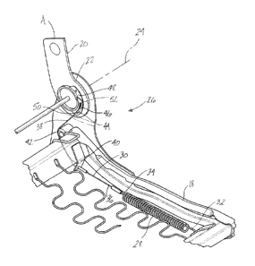
[0012] Figure 2A is a fragmentary, inner perspective view of the seat assembly
illustrating the seat back in an upright seating position and including an in-
line recliner return
mechanism according to a first embodiment of the invention;
100131 Figure 2B is a fragmentary, inner perspective view of the seat assembly
illustrating the seat back in a spring engagement/disengagement position and
including the in-
line recliner return mechanism according to the first embodiment of the
invention;
3
MN 709251 US
CA 02779920 2012-06-14
[0014] Figure 2C is a fragmentary, inner perspective view of the seat assembly
illustrating the seat back in a fold flat position and including the in-line
recliner return
mechanism according to the first embodiment of the invention;
[0015] Figure 3 is a fragmentary, partial cross-section, side view of the seat
assembly
illustrating the seat back in the upright seating position and including an in-
line recliner
return mechanism according to a second embodiment of the invention;
[00161 Figure 4 is a fragmentary, partial cross-section, side view of the seat
assembly
illustrating the seat back in the fold flat position and including the in-line
recliner return
mechanism according to the second embodiment of the invention;
[0017] Figure 5 is a fragmentary, partial cross-section, side view of the seat
assembly
illustrating the seat back in the upright seating position and including an in-
line recliner
return mechanism according to a third embodiment of the invention; and
[00181 Figure 6 is a fragmentary, inner perspective view of the seat assembly
illustrating the seat back in the upright seating position and including the
in-line recliner
return mechanism according to the third embodiment of the invention.
DETAILED DESCRIPTION OF THE EMBODIMENTS
[0019] Referring to the Figures, wherein like numerals indicate like or
corresponding
parts throughout the several views, a seat assembly for use in an automotive
vehicle is
generally shown at 10. Referring to Figure 1, the seat assembly 10 includes a
generally
horizontal seat cushion 12 and a generally upright seat back 14 operatively
coupled by a
recliner assembly 16 to the seat cushion 12. As is well known in the art, the
seat cushion 12
and seat back 14 each include corresponding frames 18, 20 covered by foam pads
and a
suitable trim cover material such as cloth, vinyl and/or leather. The recliner
assembly 16
includes a pair of spaced apart and synchronized disc recliners 22, as is well
known in the art.
The disc recliners 22 allow for pivotal or angular adjustment of the seat back
14 relative to
the seat cushion 12 about a pivot axis 24 that extends in a lateral direction.
The seat back 14
is adjustable between an upright seating position A, a plurality of reclined
seating positions
disposed rearwardly of the upright seating position A, one of which is shown
at B, an easy-
entry position C disposed forwardly of the upright seating position A, and a
fold flat position
D overlying the seat cushion 12.
4
MN 7092] US
CA 02779920 2012-06-14
100201 The disc recliners 22 are operable between a locked condition that
prevents
pivotal movement of the seat back 14 relative to the seat cushion 12 and an
unlocked
condition that allows pivotal movement of the seat back 14 relative to the
seat cushion 12. In
the unlocked condition, the seat back 14 can be adjusted between the upright
seating position
A and the plurality of reclined seating positions B. Once one of the reclined
seating positions
B is selected the disc recliners 22 are returned to the locked condition to
maintain the seat
back 14 in the selected reclined seating position B. Alternatively, in the
unlocked condition,
the seat back 14 can be dumped or pivoted forwardly to the easy-entry position
C or the fold
flat position D overlying the seat cushion 12.
[0021] The seat assembly 10 also includes an in-line recliner return
mechanism,
generally shown at 26, that is operatively coupled between the seat cushion 12
and the seat
back 14 to bias the seat back 14 forwardly about the pivot axis 24. More
specifically, when
the seat assembly 10 is unoccupied and the seat back 14 is in the upright
seating position A or
one of the reclined seating positions B, actuating the disc recliners 22 to
the unlocked
condition will allow the recliner return mechanism 26 to pivot the seat back
14 forwardly
about the pivot axis 24. Normally, a blocking mechanism (not shown) will stop
the seat back
14 at the easy-entry position C. If the seat back 14 is not blocked at the
easy-entry position
C, however, the inertia of the seat back 14 and gravity will urge the seat
back 14 to continue
pivoting forwardly to the fold flat position D.
[0022] As the seat back 14 pivots forwardly from the upright seating position
A or
one of the reclined seating positions B, the recliner return mechanism 26
ceases applying a
biasing force to the seat back 14 once the seat back 14 reaches a spring
engagement/disengagement position E, which is shown in Figure 2B. In other
words, at the
spring engagement/disengagement position E, the recliner return mechanism 26
is operatively
decoupled from the seat back 14 such that only inertia and gravity act on the
seat back 14 to
pivot the seat back 14 to the easy-entry position C or the fold flat position
D. It is appreciated
that the spring engagement/disengagement position E may or may not coincide
with the easy-
entry position C without varying from the scope of the invention.
[0023] Referring to Figures 2A through 2C, in a first embodiment of the
invention,
the recliner return mechanism 26 includes a helical extension spring 28 and a
cable 30
operatively coupled between the spring 28 and the seat back 14. The spring 28
extends
between a first end 32 that is fixedly secured to the seat cushion frame 18
and an opposite
5
MN. 709251 US
CA 02779920 2012-06-14
second end 34. The cable 30 extends between a first end 36 and a second end 38
and is
guided along the seat cushion frame 18 by a cable attachment bracket 40 and
one or more
cable routing guides 42. The first end 36 of the cable 30 is fixedly coupled
to the second end
34 of the spring 28 and the second end 38 of the cable 30 includes an
actuation pin 44
secured thereto. The actuation pin 44 is slidably coupled to a lost motion
slot 46 which is
formed in an actuation ring 48 that is fixedly secured to the seat back frame
20. The lost
motion slot 46 is adjacent to one of the disc recliners 22 and extends in a
circumferential
direction about the pivot axis 24 between a first end 50 and a second end 52.
100241 In operation, beginning with the seat back 14 in the upright seating
position A,
shown in Figure 2A, the actuation pin 44 is disposed at the first end 50 of
the lost motion slot
46. The cable 30 has a length such that with the seat back 14 in the upright
seating position
A, the spring 28 is at least partially extended. As such, a biasing force from
the spring 28
acts on the seat back 14 through the cable 30 to urge the seat back 14 to
pivot forwardly. In
response to actuating the disc recliners 22 to the unlocked condition, the
biasing force causes
the seat back 14 to pivot forwardly about the pivot axis 24. As the seat back
14 pivots
forwardly, the biasing force of the spring 28 ceases once the seat back 14
reaches the spring
engagement/disengagement position E, shown in Figure 2B. At the spring
engagement/disengagement position E, the actuation pin 44 is disposed at the
first end 50 of
the lost motion slot 46, the spring 28 is in a relaxed state, and there is no
tension in the cable
30. As such, there is no biasing force from the spring 28 acting on the seat
back 14 through
the cable 30. The pivotal movement of the seat back 14 continues until the
seat back 14
reaches the easy-entry position C or the fold flat position D, shown in Figure
2C. As the seat
back 14 pivots from the spring engagement/disengagement position E to the fold
flat position
D, the actuation pin 44 travels along the lost motion slot 46 from the first
end 50 to the
second end 52 thereof. At the fold flat position D, the actuation pin 44 is
disposed at the
second end 52 of the lost motion slot 46, the spring 28 is in the relaxed
state, and there is no
tension in the cable 30. As such, there is no biasing force from the spring 28
acting on the
seat back 14 through the cable 30 during this range of pivotal movement of the
seat back 14.
[00251 To return the seat back 14 to the upright seating position A, the seat
back 14 is
pivoted upwardly from the fold flat position D to the spring
engagement/disengagement
position E. At the same time, the actuation pin 44 travels along the lost
motion slot 46 from
the second end 52 to the first end 50 thereof. As noted above, at the spring
6
MN 709251 US
CA 02779920 2012-06-14
engagement/disengagement position E, the actuation pin 44 is disposed at the
first end 50 of
the lost motion slot 46, the spring 28 is in the relaxed state, and there is
no tension in the
cable 30. As such, there is no biasing force from the spring 28 acting on the
seat back 14
through the cable 30 during this range of pivotal movement of the seat back
14. In other
words, as the seat back 14 is pivoted from the fold flat position D toward the
spring
engagement/disengagement position E, only the weight of the seat back 14 must
be
overcome.
[0026] Continued pivotal movement of the seat back 14 towards the upright
seating
position A causes the first end 50 of the lost motion slot 46 to pull the
cable 30, thereby
tensioning the cable 30 and stretching or extending the spring 28 such that
the biasing force
fi-om the spring 28 acts on the seat back 14 through the cable 30. The biasing
force acts in a
direction opposite to the pivotal movement of the seat back 14 as the seat
back 14 is pivoted
towards the upright seating position A. The biasing force of the spring 28
increases linearly
as the seat back 14 is pivoted from the spring engagement/disengagement
position E to the
upright seating position A. The biasing force of the spring 28 continues to
increase as the
seat back 14 is pivoted to one of the reclined seating positions B. It is
appreciated that the
biasing force of the spring 28 acting on the seat back 14 through the cable 30
is sufficient to
pivot the seat back 14 forwardly from any one of the reclined seating
positions B to the
spring engagement/disengagement position E. It is further appreciated that the
seat back 14
will pivot forwardly from the spring engagement/disengagement position E to
the easy-entry
position C or the fold flat position D in response to inertia and gravity.
[00271 Referring to Figures 3 and 4, in a second embodiment of the invention,
the
recliner return mechanism 26 includes a helical extension spring 60, a
tensioner arm 62, and a
cable 64 operatively coupled between the spring 60 and the seat back 14. The
spring 60
extends between a first end 66 that is fixedly secured to the seat cushion
frame 18 and an
opposite second end 68. The tensioner arm 62 extends between a proximal end 70
that is
pivotally coupled to the seat cushion frame 18 and a distal end 72 having a
guide 74. The
tensioner arm 62 pivots between a first pivotal position, shown in Figure 4,
and a second
pivotal position, shown in Figure 3. The tensioner arm 62 is biased in a first
direction
(counterclockwise when viewed from the Figures) toward the first pivotal
position to remove
slack from the cable 64 as described in detail below. The cable 64 extends
between a first
end 76 fixedly coupled to the second end 68 of the spring 60 and a second end
78 fixedly
7
MN: 709251 US
CA 02779920 2012-06-14
coupled to the seat back frame 20 adjacent to one of the disc recliners 22.
Between the first
end 76 and the second end 78, the cable 64 is routed partially around the
guide 74 on the
tensioner arm 62 in a second direction (clockwise when viewed from the
Figures). A recliner
cable guide 79 is mounted to the seat back frame 20 adjacent one of the disc
recliners 22.
The recliner cable guide 79 is typically a plastic part for guiding the cable
64 around the disc
recliner 22 to prevent cable damage due to friction against the disc recliner
22. The recliner
cable guide 79 has a profile which the cable 64 follows in the circumferential
direction about
the pivot axis 24 when the seat back 14 is in the upright seating position A
or one of the
plurality of reclined seating positions B. The profile offsets the cable 64
from the pivot axis
24 generally in the direction which the seat back 14 pivots towards the spring
engagement/disengagement position E.
100281 In operation, beginning with the seat back 14 in the upright seating
position A,
shown in Figure 3, the cable 64 has a length such that with the tensioner arm
62 disposed in
the second pivotal position the spring 60 is at least partially extended. As
such, a biasing
force from the spring 60 acts on the seat back 14 through the cable 64 to urge
the seat back 14
to pivot forwardly. In response to actuating the disc recliners 22 to the
unlocked condition,
the biasing force causes the seat back 14 to pivot forwardly about the pivot
axis 24. As the
seat back 14 pivots forwardly, the biasing force of the spring 60 ceases once
the seat back 14
reaches the spring engagement/disengagement position E. At the spring
engagement/disengagement position E, the tensioner arm 62 is still in the
second pivotal
position, the spring 60 is in a relaxed state, and there is no tension in the
cable 64. As such,
there is no biasing force from the spring 60 acting on the seat back 14
through the cable 64.
The pivotal movement of the seat back 14 continues until the seat back 14
reaches the easy-
entry position C or the fold flat position D, shown in Figure 4. As the seat
back 14 pivots
from the spring engagement/disengagement position E to the fold flat position
D, the
tensioner arm 62 pivots in the counterclockwise direction from the second
pivotal position to
the first pivotal position to remove slack from the cable 64. At the fold flat
position D, the
tensioner arm 62 is disposed in the first pivotal position, the spring 60 is
in the relaxed state,
and there is no tension in the cable 64. As such, there is no biasing force
from the spring 60
acting on the seat back 14 through the cable 64 during this range of pivotal
movement of the
seat back 14.
8
MN: 709251 US
CA 02779920 2012-06-14
[00291 To return the seat back 14 to the upright seating position A, the seat
back 14 is
pivoted upwardly from the fold flat position D to the spring
engagement/disengagement
position E. At the same time, the seat back 14 pulls the cable 64 which causes
the tensioner
arm 62 to pivot in the clockwise direction from the first pivotal position to
the second pivotal
position. As noted above, at the spring engagement/disengagement position E,
the tensioner
arm 62 is disposed in the second pivotal position, the spring 60 is in the
relaxed state, and
there is no tension in the cable 64. As such, there is no biasing force from
the spring 60
acting on the seat back 14 through the cable 64 during this range of pivotal
movement of the
seat back 14. In other words, as the seat back 14 is pivoted from the fold
flat position D
toward the spring engagement/disengagement position E, only the weight of the
seat back 14
must be overcome.
[00301 The tensioner arm 62 cannot pivot in the clockwise direction beyond the
second pivotal position. As such, continued pivotal movement of the seat back
14 towards
the upright seating position A causes the seat back 14 to pull the cable 64,
thereby stretching
or extending the spring 60 such that the biasing force from the spring 60 acts
on the seat back
14 through the cable 64. The biasing force acts in a direction opposite to the
pivotal
movement of the seat back 14 as the seat back 14 pivots toward the upright
seating position
A. The biasing force of the spring 60 increases linearly as the seat back 14
pivots from the
spring engagement/disengagement position E to the upright seating position A.
The biasing
force of the spring 60 continues to increase as the seat back 14 pivots to one
of the reclined
seating positions B. It is appreciated that the biasing force of the spring 60
acting on the seat
back 14 through the cable 64 is sufficient to pivot the seat back 14 forwardly
from any one of
the reclined seating positions B to the spring engagement/disengagement
position E. It is
also appreciated that the biasing force acting on the seat back 14 through the
cable 64 pulls
the cable 64 against the profile of the recliner cable guide 79, and since the
profile offsets the
cable 64 from the pivot axis 24 this creates a larger moment about the pivot
axis 24 to assist
with pivoting the seat back 14 forwardly to the spring
engagement/disengagement position E.
It is further appreciated that the seat back 14 will pivot forwardly from the
spring
engagement/disengagement position E to the easy-entry position C or the fold
flat position D
in response to inertia and gravity.
[0031] Referring to Figures 5 and 6, in a third embodiment of the invention,
the
recliner return mechanism 26 includes a helical extension spring 80, a cable
tensioner (not
9
MN 70925 I US
CA 02779920 2012-06-14
shown), and a cable 82 operatively coupled between the spring 80 and the seat
back 14. The
spring 80 extends between a first end 84 that is fixedly secured to the seat
cushion frame 18
and an opposite second end 86. The cable 82 extends between a first end 88 and
a second
end 90 and is guided along the seat cushion frame 18 by a cable attachment
bracket 92 and
one or more cable routing guides 94. The first end 88 of the cable 82 is
fixedly coupled to
the second end 86 of the spring 80 and the second end 90 of the cable 82 is
fixedly coupled to
the seat back frame 20 adjacent to one of the disc recliners 22. The cable
tensioner is
mounted to the seat cushion frame 18 and is movable between a first position
and a second
position. The cable tensioner is operatively coupled to the cable 82,
generally between the
first end 88 and the second end 90, and is biased toward the first position to
remove slack
from the cable 82 as described below in detail. A recliner cable guide 96 is
mounted to the
seat back frame 20 adjacent one of the disc recliners 22. The recliner cable
guide 96 is
typically a plastic part for guiding the cable 82 around the disc recliner 22
to prevent cable
damage due to friction against the disc recliner 22. The recliner cable guide
96 has a profile
I which the cable 82 follows in the circumferential direction about the pivot
axis 24 when the
seat back 14 is in the upright seating position A or one of the plurality of
reclined seating
positions B. The profile offsets the cable 82 from the pivot axis 24 generally
in the direction
which the seat back 14 pivots towards the spring engagement/disengagement
position E.
[0032] In operation, beginning with the seat back 14 in the upright position
seating
position A, the cable 82 has a length such that with the cable tensioner
disposed in the second
position the spring 80 is at least partially extended. As such, a biasing
force from the spring
80 acts on the seat back 14 through the cable 82 to urge the seat back 14 to
pivot forwardly.
In response to actuating the disc recliners 22 to the unlocked condition, the
biasing force
causes the seat back 14 to pivot forwardly about the pivot axis 24. As the
seat back 14 pivots
forwardly, the biasing force of the spring 80 ceases once the seat back 14
reaches the spring
engagement/disengagement position E. At the spring engagement/disengagement
position E,
the cable tensioner is still in the second position, the spring 80 is in a
relaxed state, and there
is no tension in the cable 82. As such, there is no biasing force from the
spring 80 acting on
the seat back 14 through the cable 82. The pivotal movement of the seat back
14 continues
until the seat back 14 reaches the easy-entry position C or the fold flat
position D. As the seat
back 14 pivots from the spring engagement/disengagement position E to the fold
flat position
D, the cable tensioner moves from the second position to the first position to
operably remove
slack from the cable 82. At the fold flat position D, the cable tensioner is
disposed in the first
MN 70925 I US
CA 02779920 2012-06-14
position, the spring 80 is in the relaxed state, and there is no tension in
the cable 82. As such,
there is no biasing force from the spring 80 acting on the seat back 14
through the cable 82
during this range of pivotal movement of the seat back 14.
[0033] To return the seat back 14 to the upright seating position A, the seat
back 14 is
pivoted upwardly from the fold flat position D to the spring
engagement/disengagement
position E. At the same time, the seat back 14 pulls the cable 82 which causes
the cable
tensioner to move from the first position to the second position. As noted
above, at the spring
engagement/disengagement position E, the cable tensioner is disposed in the
second position,
the spring 80 is in the relaxed state, and there is no tension in the cable
82. As such, there is
no biasing force from the spring 80 acting on the seat back 14 through the
cable 82 during
this range of pivotal movement of the seat back 14. In other words, as the
seat back 14 is
pivoted from the fold flat position D toward the spring
engagement/disengagement position
E, only the weight of the seat back 14 must be overcome.
100341 The cable tensioner cannot move beyond the second position. As such,
continued pivotal movement of the seat back 14 towards the upright seating
position A causes
the seat back 14 to pull the cable 82, thereby stretching or extending the
spring 80 such that
the biasing force from the spring 80 acts on the seat back 14 through the
cable 82. The
biasing force acts in a direction opposite to the pivotal movement of the seat
back 14 as the
seat back 14 pivots toward the upright seating position A. The biasing force
of the spring 80
increases linearly as the seat back 14 pivots from the spring
engagement/disengagement
position E to the upright seating position A. The biasing force of the spring
80 continues to
increase as the seat back 14 pivots to one of the reclined seating positions
B. It is appreciated
that the biasing force of the spring 80 acting on the seat back 14 through the
cable 82 is
sufficient to pivot the seat back 14 forwardly from any one of the reclined
seating positions B
to the spring engagement/disengagement position E. It is also appreciated that
the biasing
force acting on the seat back 14 through the cable 82 pulls the cable 82
against the profile of
the recliner cable guide 96, and since the profile offsets the cable 82 from
the pivot axis 24
this creates a larger moment about the pivot axis 24 to assist with pivoting
the seat back 14
forwardly to the spring engagement/disengagement position E. It is further
appreciated that
the seat back 14 will pivot forwardly from the spring engagement/disengagement
position E
to the easy-entry position C or the fold flat position D in response to
inertia and gravity.
11
MN 709251 Us
CA 02779920 2012-06-14
[0035] The invention has been described in an illustrative manner. It is to be
understood that the terminology, which has been used, is intended to be in the
nature of
words of description rather than of limitation. Many modifications and
variations of the
invention are possible in light of the above teachings. Therefore, within the
scope of the
appended claims, the invention may be practiced other than as specifically
described.
12
MN: 709251 US