Note: Descriptions are shown in the official language in which they were submitted.
CA 02779960 2016-03-18
LOCKABLE HOLSTER RETENTION SYSTEM
CROSS-REFERENCE TO RELATED APPLICATIONS
[0001] This patent application claims the benefit of U.S. Patent
Application
Serial No. 61/280,829, filed 09 November 2009, and U.S. Patent Application
Serial
No. 61/335,856, filed 13 January 2010.
Page 1 of42
22891668.1
CA 02779960 2012-05-03
WO 2011/056239
PCT/US2010/002935
BACKGROUND OF THE INVENTION
1. Field of the Invention
[00021 This invention relates generally to handgun holsters. In
particular, the
present invention relates to a handgun holster having a lockable retention
system.
2. Description of Related Art
100031 Many users of handguns, particularly military and law enforcement
personnel, carry a handgun in a holster designed to protect the handgun and
hold it
securely. Holsters can be worn in a number of ways, such as on a belt at the
waist,
on the thigh, under an arm, or around an ankle.
(00041 Certain users of handguns must be able to quickly and easily
remove the
handgun from a holster regardless of the type of holster used. Additionally,
these
users need to be assured that, when not in use, the handgun will remain safely
in the
holster.
100051 Some holsters rely solely on friction to secure the handgun in
place. This
combination might not be suitable for situations where the gun/holster is
subject to a
great deal of movement because such movement could cause the handgun to lose
frictional engagement with the holster.
100061 Certain other holsters include a variety of strap or flap
arrangements that
prevent the removal of the firearm from the holster while the strap or flap is
in place.
With designs that rely on this method to retain a handgun, a user must first
unfasten
and/or rotate the strap/flap before the firearm can be withdrawn. Then, to re-
secure
the handgun in the holster once the handgun has been re-holstered, the user
must
physically refasten and/or rotate the strap/flap before the firearm is
securely retained
within the holster. Some users might not prefer these designs because of the
time
required to release and/or re-secure the handgun.
Page 2 of 42
CA 02779960 2012-05-03
. ,
WO 2011/056239
PCT/US2010/002935
SUMMARY OF THE INVENTION
100071 The present invention relates generally to handgun
holsters. In
particular, the present invention relates to a holster for a weapon, such as,
for
example, a handgun, having a retention system for securing a handgun such that
the
handgun is retained or locked in the holster when the retention system is
engaged,
but may be easily removed from the holster by the wearer while removal by
anyone
other than the wearer is difficult.
100081 In an illustrative, non-limiting embodiment of this
invention, the
handgun holster comprises a handgun holster having a retention system. The
retention system comprises a lever having an engagement portion and a finger
button portion, the engagement portion includes a locking projection for
engaging
an interior portion of the trigger guard of the handgun in the holster and,
thereby,
retaining the handgun in the holster.
100091 The construction of the holster prevents the locking
projection from
contacting the trigger of the handgun by limiting how far the handgun can be
inserted into the holster. The construction of the holster further facilitates
alignment
of the trigger guard with the locking projection by limiting movement of the
handgun with respect to the lever.
100101 The lever is positioned on the holster such that, when a
user depresses
the appropriate portion of the lever, thereby releasing the handgun from the
holster,
and draws the handgun from the holster, the user's index finger is positioned
to
contact the frame of the handgun, above the trigger guard.
100111 In an illustrative, non-limiting embodiment of this
invention, a biasing
element is optionally included. If included, the biasing element contacts a
front
portion of the handgun's trigger guard and is spring-biased when the handgun
is
retained, or locked, in the holster. The biasing element biases the handgun
out of
the holster and assists in maintaining contact between the locking projection
and the
trigger guard. Furthermore, the biasing element may assist in removal of the
Page 3 of 42
CA 02779960 2012-05-03
WO 2011/056239
PCT/US2010/002935
handgun from the holster when the locking projection is disengaged from the
trigger
guard.
100121 In one illustrative, non-limiting embodiment of this invention,
the holster
includes a cavity having an open top end, a bottom end, a frame/slide portion,
and a
trigger guard portion. The frame/slide portion of the cavity has greater depth
than
the trigger guard portion of the cavity. An axis extends between the
frame/slide
portion of the cavity and the trigger guard portion of the cavity.
10013] A lever having a finger button portion and an engagement portion
is
pivotally attached atop the side wall of the holster, along the axis,
approximately
between the finger button portion and the engagement portion, such that the
finger
button portion extends from the axis and is positioned above the frame/slide
portion
of the cavity and the engagement portion extends from the axis and is
positioned
above the trigger guard portion of the cavity.
[0014] The lever includes a second side facing generally toward the
holster
cavity, and the engagement portion of the lever includes a locking projection
extending from the second side of the engagement portion; wherein the lever.
100151 In certain illustrative, non-limiting embodiment of this
invention, the
holster further includes one or more ridge segments extending from the side
wall
around at least a portion of the lever so as to define a recess. The lever is
positioned
within the recess and an aperture formed in a portion of the side wall beneath
at least
a portion of the finger button portion of the lever, wherein the aperture is
formed
within the recess.
100161 Thus, the present invention automatically locks the handgun in
place in
the holster with a releasable mechanism that is easily operated by a wearer of
the
holster. However, the present mechanism is not easily accidentally disengaged
or
disengaged by anyone other than the wearer.
[0017] Accordingly, this invention provides a handgun holster, having a
retention system.
Page 4 of 42
CA 02779960 2012-05-03
WO 2011/056239
PCIATS2010/002935
[0018] This invention separately provides a safe and reliable quick-
release
handgun holster.
[0019] This invention separately provides a handgun holster having a
retention
system, which is capable of retaining a handgun securely in the holster while
permitting a quick release of the handgun when the user requires.
[0020j This invention separately provides a handgun holster having a
retention
system, which is simple to operate.
100211 This invention separately provides a handgun holster having a
retention
system, which automatically secures the handgun in the holster upon seating of
the
handgun in the holster, without requiring any additional operation by the
user.
[0022] This invention separately provides a handgun holster and a
retention
system that assists the user in positioning his or her index finger along the
frame of
the handgun, outside of and not on the trigger guard, as the handgun is drawn
from
the holster.
100231 This invention separately provides a handgun holster having an
optional
passive retention system, which can be tightened to provide increased
frictional
tension between a portion of the holster and the handgun trigger guard without
increasing the frictional tension between a remaining portion of the holster
and the
handgun.
100241 This invention separately provides a handgun holster, which is
capable of
being manufactured using injection molding production techniques.
[0025] These and other features and advantages of this invention are
described
in or are apparent from the following detailed description of the exemplary
embodiments.
=
Page 5 of 42
CA 02779960 2012-05-03
WO 2011/056239
PCT[US2010/002935
BRIEF DESCRIPTION OF THE DRAWINGS
10026] The exemplary embodiments of this invention will be described in
detail,
with reference to the following figures, wherein like reference numerals refer
to like
parts throughout the several views, and wherein:
100271 Fig. 1 shows a right perspective view of a first exemplary
embodiment of
a handgun holster having a retention system according to this invention;
100281 Fig. 2 shows a left perspective view of a first exemplary
embodiment of a
handgun holster having a retention system according to this invention;
100291 Fig. 3 shows a right side elevation view of a first exemplary
embodiment
of a handgun holster having a retention system according to this invention;
100301 Fig. 4 shows a left side elevation view of a first exemplary
embodiment
of a handgun holster having a retention system according to this invention;
100311 Fig. 5 shows a front elevation view of a first exemplary
embodiment of a
handgun holster having a retention system according to this invention;
100321 Fig. 6 shows a rear elevation view of a first exemplary embodiment
of a
handgun holster having a retention system according to this invention;
100331 Fig. 7 shows a top cross-sectional view taken along line 7-7 of
the
handgun holster of Fig. 3, illustrating the first exemplary embodiment of the
retention system according to this invention in greater detail;
10034] Fig. 8 shows a bottom plan view of a first exemplary embodiment of a
handgun holster having a retention system according to this invention;
10035] Fig. 9A shows a more detailed right side view of the handgun
holster
further illustrating the retention system according to this invention;
100361 Fig. 9B shows a more detailed cross-sectional view taken along
line 9-9
of the handgun holster of Fig. 5, illustrating the first exemplary embodiment
of the
retention system according to this invention in greater detail;
Page 6 of 42
CA 02779960 2012-05-03
WO 2011/056239
PCT/US2010/002935
100371 Fig. 10A shows a right perspective view of a second exemplary
embodiment of a handgun holster having a retention system according to this
invention;
100381 Fig. 10B shows a left perspective view of a second exemplary
embodiment of a handgun holster having a retention system according to this
invention;
100391 Fig. 11A shows a right side elevation view of a third exemplary
embodiment of a handgun holster having a retention system according to this
invention;
100401 Fig. 11B shows a left side elevation view of a third exemplary
embodiment of a handgun holster having a retention system according to this
invention;
[00411 Fig. 12A shows an exemplary embodiment of a handgun holster having
a
retention system that includes a lockout lever, wherein the lockout lever is
in a
locked position according to this invention;
100421 Fig. 12B shows an exemplary embodiment of a handgun holster having
a
retention system that includes a lockout lever, wherein the lockout lever is
in an
unlocked position according to this invention;
[00431. Fig. 13A show more detailed views of the front side of the lockout
lever
according to this invention;
100441 Fig. I3B show more detailed views of the back side of the lockout
lever
according to this invention;
100451 Fig. 14 shows an exemplary embodiment of a handgun holster having
a
retention system that may be used with a lockout lever, wherein the lockout
lever is
removed to show the are under the lockout lever;
100461 Fig. 15A shows an exemplary embodiment of a handgun holster having
a
retention system, showing a locking slider in a locked position according to
this
invention;
Page 7 of 42
CA 02779960 2012-05-03
WO 2011/056239
PCT/US2010/002935
100471 Fig. 15B shows an exemplary embodiment of a handgun holster having
a
retention system, showing the locking slider in an unlocked position according
to
this invention;
100481 Fig. 16A shows a more detailed, cross-sectional view of the
retention
system of the exemplary embodiment of a handgun holster having a retention
system
and a locking slider, showing the locking slider in a locked position
according to
this invention;
100491 Fig. 168 shows a more detailed, cross-sectional view of the
retention
system of the exemplary embodiment of a handgun holster having a retention
system
and a locking slider, showing the locking slider in an unlocked position
according to
this invention;
100501 Fig. 17 shows a rear elevation view of an exemplary handgun
holster
having a retention system and a locking slider, showing a locking slider in a
locked
position according to this invention;
100511 Fig. 18A shows an exemplary embodiment of a handgun holster having a
retention system that includes a lockout lever, wherein the lockout lever is
in a
locked position according to this invention;
[0052J Fig. I8B shows an exemplary embodiment of a handgun holster having
a
retention system that includes a lockout lever, wherein the lockout lever is
in an
unlocked position according to this invention;
100531 Fig. 19 shows an exemplary embodiment of a handgun holster having
a
retention system with a lockout key in a retention system lockout position;
10054) Fig. 20 shows an exemplary embodiment of a handgun holster having
a
retention system with a lockout key in a retention system lockout position;
(0055) Fig. 21 shows a side view of an exemplary embodiment of a handgun
holster having a retention system with a lockout band in a retention system
lockout
position;
Page 8 of 42
CA 02779960 2012-05-03
WO 2011/056239
PCIMS2010/002935
100561 Fig. 22 shows a top, cut-away view of an exemplary embodiment of a
handgun holster having a retention system with a lockout band in a retention
system
lockout position;
100571 Fig. 23 shows a front view of an exemplary embodiment of a handgun
holster having a retention system with a lockout band in a retention system
lockout
position;
100581 Fig. 24A shows an exemplary embodiment of a handgun holster having
a
retention system that includes a keyed lockout lever, wherein the keyed
lockout
lever is in a locked position according to this invention; and
10059] Fig. 24B shows an exemplary embodiment of a handgun holster having a
retention system that includes a keyed lockout lever, wherein the keyed
lockout
lever is in an unlocked position according to this invention.
Page 9 of 42
CA 02779960 2012-05-03
WO 2011/056239
PCT/US2010/002935
DETAILED DESCRIPTION OF EXEMPLARY EMBODIMENTS
100601 For simplicity and clarification, the design factors and operating
principles of the handgun holster according to this invention are explained
with
reference to various exemplary embodiments of a handgun holster according to
this
invention. The basic explanation of the design factors and operating
principles of
the handgun holster is applicable for the understanding, design, and operation
of the
handgun holster of this invention.
100611 Furthermore, it should be appreciated that, for simplicity and
clarification, the embodiments of this invention will be described with
reference to a
semiautomatic-type handgun being secured within the present holster. However,
it
should be appreciated that the operating principles of the handgun holster of
this
invention may also be employed to construct holsters or holders for any
revolver or
semiautomatic-type handgun, edged weapons as well as less than lethal products
(i.e., tasers, pepper spray, mace canisters, or batons), so long as these
items have an
appropriate ledge or void that may be engaged or retained by a locking
projection or
other retaining means. Furthermore, it is also within the scope of the present
invention that the present holster may be employed as a pouch for tactical
accessories, such as ammunition magazines and/or flashlights, as well as for
everyday items such as cell phones or personal digital assistants.
100621 It should also be appreciated that the terms "handgun", "handgun
holster", and "weapon" are used for basic explanation and understanding of the
operation of the systems, methods, and apparatuses of this invention.
Therefore, the
terms "handgun", "handgun holster", and "weapon" are not to be construed as
limiting the systems, methods, and apparatuses of this invention.
100631 Figs. 1-9B show various views of a first, illustrative, non-limiting
embodiment of a handgun holster 100 having a retention system according to
this
invention. It should be appreciated that the holster 100 is adapted to retain
a
semiautomatic-type handgun. The semiautomatic-type handgun includes a slide, a
Page 10 of 42
CA 02779960 2012-05-03
WO 2011/056239
PCT/US2010/002935
grip, a trigger, and a trigger guard. The trigger guard includes an inner
surface,
which defines an area wherein the trigger is located and allows a user's
finger access
to the trigger, and an outer surface, which defines the outer perimeter of the
trigger
guard.
100641 As shown in Figs. 1-9B, the holster 100 includes a body 103 defining
a
cavity 105 for receiving and holding the handgun. The body 103 comprises a
pair of
opposed side walls comprising a first side wall 110 and a second side wall
120.
Typically, the first side wall 110 is considered the outer side of the holster
and is
worn away from the user's body, while the second side wall 120 is considered
the
inner side of the holster and is worn against or adjacent the user's body.
100651 In various exemplary embodiments, the body 103 further comprises
at
least some of a front wall 130 and a rear wall 140. However, it should be
appreciated that the holster 100 may be formed such that one or more of the
first
side wall 110, the second side wall 120, the front wall 130, and/or the rear
wall 140
5 is/are sufficient to define the cavity 105 for receiving the handgun and
the remaining
walls are not included.
100661= The cavity 105 includes an open top end 101 and a bottom end 102
and
may be formed from any number or combination of walls, including, for example,
a
single, continuous wall or multiple coupled or joined walls. Alternatively,
the
cavity 105 may be formed by a material being shaped or bent in a substantial
"U"
shape. Thus, the cavity 105 may be formed by any cavity, space, or platform
that is
capable of retaining a handgun.
100671 As identified in Fig. 3, an axis A extends generally from the top
end 101
to the bottom end 102, between a frame/slide portion 109 of the cavity 105 and
a
trigger guard portion 107 of the cavity 105. The frame/slide portion 107 of
the
cavity 105 generally has greater depth than the trigger guard portion 109 of
the
cavity 105.
Page I I of 42
CA 02779960 2012-05-03
WO 2011/056239
PCT/US2010/002935
100681 It should be noted that the walls of the holster 100 may generally
be
planar. Alternatively, the walls of the holster 100 may be contoured or shaped
to
better accommodate a specific type or model of handgun to be retained within
the
holster 100.
100691 In various exemplary embodiments, the holster 100 is substantially
rigid
and is formed of a polymeric material such as a polymeric composite. Alternate
materials of construction may include one or more of the following: steel,
aluminum, titanium, and/or other metals, as well as various alloys and
composites
thereof, glass-hardened polymers, polymer or fiber reinforced metals, carbon
fiber
ici or glass fiber composites, continuous fibers in combination with
thermoset and
thermoplastic resins, chopped glass or carbon fibers used for injection
molding
compounds, laminate glass or carbon fiber, epoxy laminates, woven glass fiber
laminates, impregnate fibers, polyester resins, epoxy resins, phenolic resins,
polyimide resins, cyanate resins, high-strength plastics, nylon, glass, or
polymer
fiber reinforced plastics, thermoform and/or thermoset sheet materials, or the
like,
and/or various combinations of the foregoing.
[0070I In various exemplary embodiments, at least certain components of
the
holster 100 may be formed of any known or later developed, substantially
flexible
material(s) such as a polymeric material, leather, foam, foam laminates,
natural and
man-made (synthetic) fabrics, natural and man-made (synthetic) fabric
laminates,
moldable honeycomb materials, or the like, and/or various combinations of the
foregoing.
10071I Thus, it should be understood that the material or materials used
to form
the holster 100 and/or various components of the holster 100 is a design
choice
based on the desired appearance and functionality of the holster 100.
100721 In various exemplary embodiments, the holster 100 includes
attachment
points 170, which provide means for fastening the holster to a holster holding
device
such as the holster holding device 175 illustrated in phantom in Figs. 3 and
4.
Page 12 of 42
CA 02779960 2012-05-03
WO 2011/056239
PCT/US2010/002935
Alternatively, the means for fastening the holster may comprise a clip or hook
adapted to be clipped over, for example, a belt. In further exemplary
embodiments,
means for fastening the holster may comprise one or more quick-disconnect or
other
couplings may be provided on or adjacent the second side wall 120 of the
holster
100, which may be permanently or removably coupled to corresponding and
cooperating coupling(s) provided on a belt or other carrier or platform. In
still other
exemplary embodiments, the holster 100 may comprise an integral belt, or may
comprise one or more connections for attachment to a chest, ankle, leg,
shoulder, or
other harness or band, or for otherwise securing the holster to a user or the
user's
lo apparel.
100731 In various exemplary embodiments, one or both of the side walls
include
optional slots 180 and 182, which define a passive retention portion 184.
Although
not shown in the present figures, the inner surface of the passive retention
portion
184 may optionally include a raised area, which provides for additional
frictional
engagement of the trigger guard of the handgun. One or more retention screws
186
may be tightened or loosened to adjust the degree of frictional retention of
the
handgun by the passive retention portion 184.
(0074) The passive retention portion 184, if included, may be adjusted,
via the
one or more retention screws 186, to provide an adjustable frictional tension
between the passive retention portion 184 and the handgun trigger guard,
without
increasing the frictional tension between a remaining portion of the holster
100 and
the handgun.
100751 As further shown in Figs. 1-9B, the holster 100 comprises a
retention
means that is capable of retaining a handgun securely in the holster 100 by
restricting withdrawal of the handgun from the cavity 105 of the holster 100
while
permitting a quick release of the handgun when the user requires. The
retention
means comprises a lever 150, having a first side facing generally outward from
the
holster 100, away from the cavity 105 formed by the holster 100, and a second
side
Page 13 of 42
CA 02779960 2012-05-03
, .
WO 2011/056239
PCT/US2010/002935
facing toward the cavity 105 formed by the holster 100. The lever 150
comprises at
least some of a finger button portion 151 and an engagement portion 155.
100761 In various exemplary embodiments, the first side of the
finger button
portion 151 includes a textured portion (not shown). In this manner, the
finger
button portion 151 may be distinguished tactilely from other portions of the
lever
150 or the holster 100.
100771 In various exemplary, non-limiting embodiments, lever
150 is pivotally
connected to the first side wall 110, approximately between the finger button
portion
151 and the engagement portion 155, via a fulcrum or pivot pin 160. In various
exemplary embodiments, the pivot pin 160 is positioned substantially parallel
to a
vertical axis of the holster 100, substantially perpendicular to a vertical
axis of the
holster 100, at a substantially acute angle relative to a vertical axis of the
holster
100, or at a substantially obtuse angle relative to a vertical axis of the
holster 100.
Thus, the pivot pin 160 may be positioned at any angle relative to a vertical
axis of
the holster 100.
100781 The pivot pin 160 may extend all or part of the way
across the width of
the lever 150.
10079J In various exemplary embodiments, the lever 150 may
include a first and
a second protrusion extending from the lever 150. Corresponding first and
second
indentions, indentations, notches, grooves, or dimples may be formed in the
first
side wall 110. In these exemplary embodiments, the first and second
protrusions are
formed so as to operate in cooperating relationship with the first and second
dimples
such that the lever 150 may be pivotally attached, via the first and second
protrusions and the first and second dimples, to the first side wall 110
approximately
between a finger button portion 151 and the engagement portion 155. Thus, the
pivot pin 160 is replaced by the first and second protrusions.
100801 Alternatively, the lever 150 may include first and
second dimples while
the first sidewall 110 includes first and second protrusions. In these
exemplary
- Page 14 of 42
CA 02779960 2012-05-03
WO 2011/056239
PCT/US2010/002935
embodiments, the first and second dimples are formed so as to operate in
cooperating relationship with the first and second protrusions such that the
lever 150
may be pivotably attached, via the first and second dimples and the first and
second
protrusions, to the first side wall 110 approximately between the finger
button
portion 151 and the engagement portion 155.
100811 The lever 150 is pivotable between an engaged position for
securing the
handgun within the cavity 105 of the holster 100 and a disengaged position for
removal of the handgun. In various exemplary embodiments, the lever 150 may
pivot between the engaged position and the disengaged position. Alternatively,
the
lever 150 may be pivotably positioned and/or retained between either the
engaged
position or the disengaged position.
100821 In various exemplary embodiments, the lever 150 may be biased to
an
engaged position whether the handgun is present in the holster 100 or absent
from
the holster 100. In various exemplary embodiments, biasing of the lever 150
may be
accomplished by, for example, a spring means 165.
[0083] It should be appreciated that any suitable biasing means, element,
or
mechanism may be used to form the spring means 165. For example, in various
illustrative, non-limiting embodiments of this invention, the spring means 165
may
comprise a portion of spring steel, a helical spring, a compression coil
spring, a
cylindrical coil spring, a conical coil spring, a tension coil spring, a leaf
spring, a V-
spring, a cantilever spring, a spring washer, a flexible extension of the
lever 150 or
the first side wall 110, a stretched or tensioned material, such as, for
example, a
rubber band, or any other element, material, or mechanism usable to bias the
lever
150.
= 100841 It should be understood that the overall size, shape, and
thickness of the
spring means 165 will vary depending on the type and rigidity of the
particular
material used to form the spring means 165.
Page 15 of 42
CA 02779960 2012-05-03
WO 2011/056239
PCT/US2010/002935
[0085] The engagement portion 155 of the lever 150 includes a locking
projection 156, formed on the second side of the engagement portion 155. In
certain
exemplary embodiments, the locking projection 156 optionally extends
substantially
perpendicularly from the second side of the engagement and 155.
[0086] In various exemplary, nonlimiting embodiments, the locking
projection
156 includes a ramp surface 157 and is shaped generally to match the contour
of a
portion of the inner surface of the trigger guard. Alternatively, the locking
projection 156 may terminate in a radiused or not radiused manner.
Particularly if
the trigger guard of the handgun that is to be carried within the holster 100
is itself
radiused, the ramp surface 157 may not be included.
[0087] Regardless of the particular handgun used, the locking projection
156
should be shaped so that there is no possibility that the locking projection
156 can at
any time contact the trigger of the handgun. When the handgun is pushed as far
forward as possible into the holster 100 and the trigger guard has come to
rest
against the trigger guard support wall 145, there should be a space between
the
locking projection 156 and the trigger of the handgun.
[0088] When the lever 150 is in the engaged position, the locking
projection 156
protrudes from the second side of the engagement portion 155, into the cavity
105
formed in the holster 100, via an opening 115 in the first side wall 110. In
this
manner, the locking projection 156 may extend inside the cavity 105 and inside
the
trigger guard of a handgun that is placed into the holster 100 and, thereby,
retain the
handgun in the holster 100.
100891 In various exemplary embodiments, the locking projection 156
protrudes
into the cavity 105 for a distance that is less than the width of the trigger
guard.
Alternatively, the locking projection 156 may protrude into the cavity 105 for
a
distance that is equal to or greater than the width of the trigger guard.
[00901 In addition, when the lever 150 is in the engaged position and is
retaining
a handgun in place, the clearance between the locking projection 156 and the
trigger
Page 16 of 42
CA 02779960 2012-05-03
WO 2011/056239
PCT/US2010/002935
guard support wall 145 should be such that there is room for the slight arc or
plunger-type movement of the locking projection 156 when the finger button
portion
151 is depressed.
100911 Thus, the retention means is automatically disengaged as the outer
surface of the handgun's trigger guard contacts the locking projection 156 and
is
subsequently engaged when the inner surface of the trigger guard has passed
the
locking projection 156 and the handgun is appropriately retained in the
holster 100.
100921 As illustrated in Figs. 1 and 3, the holster 100 can be divided,
along an
axis that extends from the pivot pin 160, along the first side wall 110 of the
holster
100, into a frame/slide portion and a trigger guard portion. The frame/slide
portion
is contoured to accept at least a portion of a frame/slide of a handgun and
the trigger
guard portion is contoured to accept at least a portion of a trigger guard of
a
handgun. Thus, it can be seen that the finger button portion 151 extends into
the
frame/slide portion of the holster and the engagement portion 155 extends into
the
trigger guard portion of the holster 100.
100931 As at least a portion of each holster 100 is formed to accommodate
and
securely retain a specific type of handgun. The construction of the holster
100 also
prevents the locking projection 156 from contacting the trigger of the
inserted
handgun by limiting how far the handgun can be inserted into the holster 100.
100941 In various exemplary embodiments, a trigger guard support wall 145
is
generally formed by a portion of the body of the holster 100. The trigger
guard
support wall 145 is shaped generally to match the contours of at least a
portion of
the outer surface of the trigger guard. The trigger guard support wall 145 is
formed
so as to contact at least a portion of the outer surface of the trigger guard
of the
inserted handgun and further limit how far the handgun can be inserted into
the
holster 100.
100951 The construction of the holster 100 further facilitates alignment
of the
trigger guard with the locking projection 156 by limiting lateral movement of
the
Page 17 of 42
CA 02779960 2012-05-03
WO 2011/056239
PCT/US2010/002935
handgun with respect to the lever 150 and the locking projection 156 without
preventing a user from easily holstering or drawing the handgun.
100961 In various exemplary embodiments, an optional ridge 118 is formed
in
the first side wall 110 around at least a portion of the lever 150. Generally,
the ridge
does not contact the lever 150, but provides a perimeter around at least a
portion of
the lever 150 to reduce the likelihood that the lever 150 will be
inadvertently
manipulated and to aid in the proper placement of a user's finger on the
finger
button portion 151 of the lever 150. The ridge 118 may include a textured
portion
(not shown), such that the ridge 118 may be distinguished tactilely from other
portions of the holster 100 or the lever 150. The ridge 118 may include a gap
or
valley formed so as to accommodate a user's finger if the finger would extend
beyond the finger button portion 151 of the lever 150.
100971 In various exemplary embodiments, the optional ridge 118 is
comprised
of one or more ridge segments 118 and/or 119 that are formed around at least a
portion of the lever 150.
[0098] In various exemplary embodiments, a recess 117 is defined within
the
optional ridge 118 or ridge segments 118 and/or 119.
100991 Although Figs. 1-9B show the lever 150 connected to the first side
wall
110, it should be appreciated that in various exemplary embodiments, the lever
150
may be connected to the second side wall 120.
100100] In an illustrative, non-limiting embodiment of this invention, a
biasing
element 190 is optionally included. If included, the biasing element 190
extends
towards the locking projection 156, covering substantially the entire distance
between the trigger guard support wall 145 and the locking projection 156. In
various exemplary embodiments, the biasing element 190 does not touch the
locking
projection 156.
(001011 It should be appreciated that any suitable spring mechanism may be
used
to form the biasing element 190. The overall size, shape, and thickness of the
Page 18 of 42
CA 02779960 2012-05-03
WO 2011/056239
PCT/US2010/002935
biasing element 190 will vary depending on the type and rigidity of the
particular
material used to form the biasing element 190.
100102] The biasing element 190 is configured to contact the outer surface of
the
trigger guard and is spring-biased (as shown in phantom by 190) when the
handgun
is retained, or locked, in the holster. In a compressed position, the tension
of the
biasing element 190 biases the handgun outward and assists in maintaining
contact
between the locking projection 156 and the inner surface of the trigger guard.
1001031 Furthermore, the biasing element 190 may assist in removal of the
handgun from the holster when the locking projection is disengaged from the
trigger
guard.
1001041 The biasing element 190 may be configured in a number of ways, and
may be attached to the holster 100 by any suitable method. In one exemplary
embodiment, the biasing element 190 is molded as an integral part of the
holster
100.
100105] An aperture 116 is formed in a portion of the first side wall 110,
within
the recess 117, beneath at least a portion of the finger button portion 151 of
the lever
150. Among other things, the aperture 116 allows dirt and/or debris that may
find
its way under the finger button portion 151 of the lever 150 to be pushed into
the
cavity 105. In this manner, dirt and/or debris is not permitted to build up
underneath
the finger button portion 151 of the lever 150 and keep the finger button
portion 151
from being depressed by a user.
1001061 During use of the holster 100 having a retention system, as a user
begins
to holster the handgun, the handgun is inserted into the cavity 105 of the
holster,
muzzle first, and is guided into position by at least some of the first side
wall 110,
the second side wall 120, the front wall 130, and the rear wall 140.
1001071 As the handgun is inserted further into the cavity 105, the outer
surface
of the trigger guard will contact the ramp surface 157 of the locking
projection 156.
The shape of the ramp surface 157 allows the locking projection 156 to ride
along
Page 19 of 42
CA 02779960 2012-05-03
WO 2011/056239
PCT/US2010/002935
the surface of the trigger guard and displace the locking projection 156 of
the lever
150. As the locking projection 156 rides along the surface of the trigger
guard, the
bias of the lever 150 is overcome and the lever 150 is pivoted towards the
disengaged position and the handgun is permitted to be seated in the cavity
105 of
the holster. The trigger guard is prevented from moving in a direction
opposite the
locking projection 156 by the position of the first side wall 110 and the
second side
wall 120.
(001081 As the handgun is further seated into the holster, the trigger guard
continues to displace the locking projection 156 and the lever 150 continues
to pivot
until the trigger guard passes a point of contact with a farthest extent of
the locking
projection 156 and clears the locking projection 156. When the trigger guard
passes
the locking projection 156, the lever 150 may be biased, via the spring means
165,
to pivot back to the engaged position.
[00109] Thus, the
handgun is secured in the cavity 105 of the holster by operation
of the locking projection 156 blocking removal of the handgun, via the inner
surface
of the trigger guard. While the handgun is fully seated in the cavity 105 of
the
holster 100 with the lever 150 biased to the engaged position, removal of the
handgun is not permitted, as the locking projection 156 does not allow the
trigger
guard to pass by. When the handgun is secured in place, removal force applied
to
the handgun will not remove the handgun from the holster 100 unless the finger
button portion 151 is pivoted and the locking projection 156 is brought out of
the
way of the inner surface of the trigger guard.
100110] In order to release and unholster the handgun, the user depresses the
finger button portion 151 of the lever 150, pivoting the finger button portion
151
towards the cavity 105. At some point, the first side wall 110 will stop the
inward
movement of the finger button portion 151, thus eliminating the possibility
that the
finger button portion 151 can prevent the removal of the handgun by contacting
the
trigger or constricting the trigger guard.
Page 20 of 42
CA 02779960 2012-05-03
WO 2011/056239
PCMS2010/002935
1001111 As the finger button portion 151 of the lever 150 is depressed, the
bias of
the lever 150 is overcome, the lever 150 is pivoted towards the disengaged
position,
and the locking projection 156 of the engagement portion 155 is at least
partially
withdrawn from the opening 115 and out of the holster cavity 105.
1001121 When the finger button portion 151 has been depressed sufficiently,
such
that the locking projection 156 of the engagement portion 155 is sufficiently
withdrawn from the holster cavity 105, such that the locking projection 156
clears
the inner surface of the trigger guard, the handgun's trigger guard will no
longer be
blocked by the locking projection 156, and the handgun can be withdrawn from
the
holster 100.
1001131 In various exemplary embodiments wherein the first side wall 110 is
worn away from the user's body and the second side wall 120 is worn adjacent
the
user's body, the finger button portion 151 may be positioned such that, as the
finger
button portion 151 is depressed, the user's index finger is positioned along
the frame
of the handgun, between the trigger guard and the slide. Therefore, as the
handgun
is withdrawn from the holster 100 the user's index finger is positioned to
contact the
frame of the handgun, above the trigger guard, and not the trigger guard or
the
trigger.
1001141 The holster 100, as shown and described with reference to Figs. 1-9B,
is
oriented such that the first side wall 110 is worn away from the user's body
and the
second side wall 120 is worn adjacent the user's body, such that the lever 150
is
generally accessible by the user's index finger. However, in various other
exemplary embodiments, the first side wall 110 is oriented to be worn adjacent
the
user's body and the second side wall 120 is oriented to be worn away from the
user's
body. In these exemplary embodiments, the lever 150 is generally accessible by
the
user's thumb.
1001151 Figs. 10A and 10B show a right perspective view and a left perspective
view, respectively, of a second exemplary embodiment of a handgun holster 200
Page 21 of 42
CA 02779960 2012-05-03
WO 2011/056239
PCT/US2010/002935
having a retention system according to this invention. As shown in Figs. 10A
and
10B, the handgun holster 200 includes a body 203 defining a cavity 205 for
receiving and holding the handgun. The body 203 comprises a pair of opposed
side
walls comprising a first side wall 210, an optional ridge 218 and/or ridge
segments
218 and/or 219, a second side wall 220, a front wall 230, and a rear wall 240.
The
handgun holster 200 further comprises attachment points 270, optional slots
284 and
282, a passive retention screw 286, and a retention means comprising a lever
250.
[00116] It should be understood that each of these elements corresponds to and
operates similarly to the body 103, the cavity 105, the first side wall 110,
the
optional ridge 118 and/or ridge segments 118 and/or 119, the second side wall
120,
the front wall 130, the rear wall 140, the attachment points 170, the optional
slots
180 and 182, the passive retention screw 186, the retention means, and the
lever
150, as described above with reference to Figs. 1-9B.
[00117] However, as shown in Figs. 10A and 10B, the first side wall 210, the
second side wall 220, and the front wall 230 of the handgun holster are
extended, as
compared to the holster 100.
[001181 The extended first side wall 210, second side wall 220, and front wall
230 perform at least three functions. First, the extended walls more fully
surround
and protect the handgun when the handgun is secured in the holster 200.
Second,
the extended walls serve to help better guide a handgun into the holster 200.
Third,
the extended walls serve to add a measure of strength and rigidity to the
entire
structure of the holster 200.
1001191 Figs. 11A and 11B show a right perspective view and a left
perspective
view, respectively, of a second exemplary embodiment of a handgun holster 300
having a retention system according to this invention. As shown in Figs. 11A
and
11B, the handgun holster 300 includes an open top end 301 and a bottom end
302.
The handgun holster 300 further includes a body 303 defining a cavity 305
(having a
Page 22 of 42
CA 02779960 2012-05-03
WO 2011/056239
PCT/US2010/002935
trigger guard portion 307 and a frame/slide portion 309) for receiving and
holding
the handgun.
1001201 The body 303 comprises a pair of opposed side walls comprising a first
side wall 310, an aperture 316, a recess 317, an optional ridge 318 and/or
ridge
segments 318 and/or 319, a second side wall 320, a front wall 330, and a rear
wall
340. The handgun holster 300 further comprises attachment points 370, optional
slots 384 and 382, a passive retention screw 386, optionally the biasing
element 390,
and a retention means comprising a lever 350 having a finger button portion
351 and
an engagement portion 355. The lever 350 is pivotally connected, via a pivot
pin
360, to the first side wall 310.
[00121] It should be understood that each of these elements corresponds to and
operates similarly to the body 103 and/or 203, the cavity 105 and/or 205, the
first
side wall 110 and/or 210, the aperture 116 and/or 216, the recess 117 and/or
217, the
optional ridge 118 and/or 218, the optional ridge segments 118 and/or 119
and/or
218 and/or 219, the second side wall 120 and/or 220, the front wall 130 and/or
230,
the rear wall 140 and/or 240, the pivot pin 160 and/or 260, the attachment
points 170
and/or 270, the optional slots 180 and 182 and/or 280 and 282, the passive
retention
screw 186 and/or 286, the retention means, the optional biasing element 190
and/or
290 (not shown), and the lever 150 and/or 250 having the finger button portion
151
and/or 251 and the engagement portion 155 and/or 255, as described above with
reference to Figs. 1-10B.
1001221 However, as shown in Figs. 11A and 11B, the first side wall 310,
the
second side wall 320, and the front wall 330 of the handgun holster 300 are
slightly
different from the respective side walls and front wall of the handgun
holsters 100
and 200.
1001231 Additionally, as shown in Figs. 11A and 11B, the optional ridge
segments 319 extend from the finger button and 355 of the lever 350 to the top
of
the first side wall 310. A trough 312 is formed between the ridge segments
319, so
Page 23 of 42
CA 02779960 2012-05-03
WO 2011/056239
PCT/IJS2010/002935
as to further aid in the proper placement of a user's finger on the finger
button
portion 351 of the lever 350. It should be should appreciate that the ridge
segments
319 may include a textured portion (not shown), such that the ridge segments
319
may be distinguished tactilely from other portions of the holster 300 or the
lever
350.
[00124] Figs. 12A-14 show various views of a handgun holster 400 having a
retention system that includes a lockout lever 491 and the various components
the
lockable holster retention system of this invention. As shown in Figs. 12A-14,
the
handgun holster 400 includes an open top end 401 and a bottom end 402. The
handgun holster 400 further includes a body 403 defining a cavity 405 (having
a
trigger guard portion 407 and a frame/slide portion 409) for receiving and
holding .
the handgun.
1001251 The body 403 comprises a pair of opposed side walls comprising a first
side wall 410, a trough 412, an aperture 416, a recess 417, an optional ridge
418
and/or ridge segments 418 and/or 419, a second side wall 420 (not shown), a
front
wall 430, and a rear wall 440. The handgun holster 400 further comprises
attachment points 470 (not shown), optional slots 484 and 482 (not shown), a
passive retention screw 486, optionally the biasing element 490 (not shown),
and a
retention means comprising a lever 450 having a finger button portion 451 and
an
engagement portion 455. The lever 450 is pivotally connected, via a pivot pin
460,
to the first side wall 410.
[00126] It should be understood that each of these elements of the holster
400
shown in Figs. 12A-14 correspond to and operate similarly to the elements of
holsters 100-300, as described above with reference to Figs. 1-11B. However,
as
illustrated in Figs. 12A-14, the first side wall 410, the second side wall 420
(not
shown), and the front wall 430 of the handgun holster 400 are slightly
different from
the respective side walls and front wall of the handgun holsters 100-300.
Page 24 of 42
CA 02779960 2012-05-03
WO 2011/056239
PCT/US2010/002935
1001271 However, as shown in Figs. 12A-14, a lockout lever 491 is
pivotably
attached, via a screw or pivot pin 498, to the first side wall such that the
lockout
lever 491 is able to be rotated between a locked position (as illustrated in
Fig. 12A)
and an unlocked position (as illustrated in Fig. I2B).
100128] As illustrated in Fig. 13A, the lockout lever 491 includes a finger
engaging portion or ridge 492 that can be engaged or urged by a user's finger
to
pivot or rotate the lockout lever 491 between the locked and unlocked
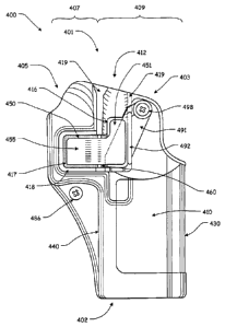
positions.
1001291 The lockout lever 491 includes a locking portion 493 that, when the
lockout lever 491 is in the locked position (as illustrated in Fig. 12A),
extends below
the finger button portion 451 of the release lever 450 to block the finger
button
portion 451 of the release lever 450 and keep the release lever 450 from being
pivoted to the disengaged position, if an attempt is made to pivot the release
lever
450 from the engaged to the disengaged position.
[00130] When the lockout lever 491 is in the unlocked position (as
illustrated in
Fig. 12B), the locking portion of the lockout lever 491 is withdrawn from
beneath
the finger button portion 451 of the release lever 450 so as to allow the
finger button
portion 451 of the release lever 450 to be pivoted to the disengaged position.
[00131] In certain exemplary embodiments, the lockout lever 491 is freely
rotatable between the locked position and the unlocked position.
Alternatively, the
lockout lever 491 may be frictionally maintained, by, for example, frictional
engagement between the holster body 403 and the lockout lever 491, in either
the
locked or the unlocked position unless a force is applied, i.e., by a user's
finger, to
slide the lockout lever 491 to the locked or unlocked position. In various
exemplary
embodiments, frictional engagement between the surfaces of the holster body
403
and the lockout lever 491 works to maintain the lockout lever 491 in a desired
position.
1001321 In other exemplary embodiments, one or more mating protrusions 495
and/or detents 496 (as illustrated most clearly in Figs. 13B and 14), or other
means
Page 25 of 42
CA 02779960 2012-05-03
=
WO 2011/056239
PCPUS2010/002935
may be provided to maintain the lockout lever 491 in the locked or unlocked
position.
1001331 In order for a user to depresses the finger button portion 451
of the
release lever 450 a sufficient distance to pivot the release lever 450 to the
disengaged position, the lockout lever 491 must be in the unlocked position
(as
illustrated in Fig. 12B). If the lockout lever 491 is in the locked position
(as
illustrated in Fig. 12A), the locking portion 493 is positioned so as to
contact a
bottom surface of the finger button portion 451 and block the finger button
portion
451 of the release lever 450 and keep the release lever 450 from being pivoted
to the
disengaged position.
[00134] In various exemplary embodiments, the lockout lever 491 may include
one or more lockout apertures (not shown). If included, the lockout apertures
allow
a lock or other device to be positioned within a portion of the locking
portion to
maintain the lockout lever 491 in the locked or unlocked position.
[00135] Figs. 15A and 15B show a right side view and Fig. 17 shows a rear view
of an exemplary embodiment of a handgun holster 500 having a retention system
according to this invention. Fig. 16A shows a more detailed, cross-sectional
view of
the retention system of the retention system of the handgun holster 500,
showing the
locking slider 591 in a locked position, while Fig. I6B shows a more detailed,
cross-
sectional view of the retention system of the retention system of the handgun
holster
500, showing the locking slider 591 in an unlocked position.
[00136] As shown in Figs. 15A-17, the handgun holster 500 includes an open top
end 501 and a bottom end 502. The handgun holster 500 further includes a body
503 defining a cavity 505 (having a trigger guard portion 507 and a
frame/slide
portion 509) for receiving and holding the handgun.
1001371 The body 503 comprises a pair of opposed side walls comprising a first
side wall 510, a trough 512, an aperture 516, a recess 517, an optional ridge
518
and/or ridge segments 518 and/or 519, a second side wall 520 (not shown), a
front
Page 26 of 42
CA 02779960 2012-05-03
=
WO 2011/056239
PCT/US2010/002935
wall 530, and a rear wall 540. The handgun holster 500 further comprises
attachment points 570 (not shown), optional slots 584 and 582 (not shown), a
passive retention screw 586, optionally the biasing element 590 (not shown),
and a
retention means comprising a lever 550 having a finger button portion 551 and
an
engagement portion 555. The lever 550 is pivotally connected, via a pivot pin
560,
to the first side wall 510.
1001381 It should be understood that each of these elements of the holster 500
shown in Figs. 15A-17 correspond to and operate similarly to the elements of
holsters 100-400, as described above with reference to Figs. 1-14.
1001391 However, as shown in Figs. 15A-17, a slot 597 is formed through a
portion of the ridge 518 such that a body portion 596 of a locking slider 591
is
capable of being slidably maintained within the slot 597.
1001401 The body portion 596 of the locking slider 591 extends from a finger
engaging portion 592 to a slide stop portion 594 and includes a notch 598 form
and
in a proportion of the locking slider body portion 596. When slidably
positioned
within the slot 597, the locking slider 591 is able to slide between a locked
position
(as illustrated in Figs. 15A and 16A) and an unlocked position (as illustrated
in Figs.
15B and 16B). The finger engaging portion 592 and the slide stop portion 594
engage portions of the reached 518 so as to maintain the locking slider 591
within
the slot 597.
1001411 The notch 598 is shaped so as to allow the engagement portion 555 of
the
lever 550 to pass therethrough when the locking slider 591 is in the unlocked
position and the notch 598 is aligned with the impeachment end 555 (as
illustrated
in Figs. 15B and 16B). However, when the locking slider 591 is in the locked
position, the body portion 596 is positioned so as to engage the engagement
portion
555 of the lever 550 if an attempt is made to pivot the lever 550 from the
engaged to
the disengaged position and keep the lever 550 from pivoting to the disengaged
position (as illustrated in Figs. 15A and 16A).
Page 27 of 42
CA 02779960 2012-05-03
WO 2011/056239
PCT/US2010/002935
[00142] In certain exemplary embodiments, the locking slider 591 may freely
slide between the locked position and the unlocked position. Alternatively,
the
locking slider 591 may be naturally maintained either the locked or the
unlocked
position within the slot 597 unless a force is applied, i.e., by a user's
finger, to slide
the locking slider 591 to the locked or unlocked position. In various
exemplary
embodiments, frictional engagement between the surfaces of the slot 597 and
the
locking slider 591 work to maintain the locking slider and a desired position.
In
other exemplary embodiments, one or more mating protrusions and/or detents or
other means may be provided to maintain the locking slider and the locked or
unlocked position.
1001431 In order for a user to depresses the finger button portion 551 of
the lever
550 of the holster 500 a sufficient distance to pivot the lever 550 to the
disengaged
position, the locking slider 591 must be in the unlocked position (as
illustrated in
Figs. 15A and 16A). If the locking slider 591 is in the locked position (as
illustrated
in Figs. 15B and I6B), the body portion 596 is positioned so as to engage the
engagement portion 555 of the lever 550 and keep the lever 550 from being
pivoted
to the disengaged position.
1001441 In various exemplary embodiments, the locking slider 591 may include
one or more lockout apertures 593 and/or 595. If included, the lockout
apertures
593 and/or 595 allow a lock or other device to be positioned within a portion
of the
body portion 596 to maintain the locking slider 591 in the locked or unlocked
position.
[00145] Fig. 17 shows handgun holster having a retention system and a locking
slider 591, wherein the locking slider 591 is in a locked position according
to this
invention.
[00146] Figs. 18A and 18B show an exemplary embodiment of a handgun holster
600 having a retention system according to this invention. Fig. 18A shows the
Page 28 of 42
CA 02779960 2012-05-03
WO 2011/056239
PCT/US2010/002935
lockout lever 691 in a locked position, while Fig. 18B shows the lockout lever
691
in an unlocked position.
1001471 As shown in Figs. I 8A and 18B, the handgun holster 600 includes an
open top end 601 and a bottom end 602. The handgun holster 600 further
includes a
body 603 defining a cavity 605 (having a trigger guard portion 607 and a
frame/slide
portion 609) for receiving and holding the handgun.
1001481 The body 603 comprises a pair of opposed side walls comprising a first
side wall 610, a trough 612, an aperture 616, a recess 617, an optional ridge
618
and/or ridge segments 618 and/or 619, a second side wall 620 (not shown), a
front
wall 630, and a rear wall 640. The handgun holster 600 further comprises
attachment points 670 (not shown), optional slots 684 and 682 (not shown), a
passive retention screw 686, optionally the biasing element 690 (not shown),
and a
retention means comprising a lever 650 having a finger button portion 651 and
an
engagement portion 655. The lever 650 is pivotally connected, via a pivot pin
660,
to the first side wall 610.
1001491 It should be understood that each of these elements of the holster 600
shown in Figs. 18A and 18B correspond to and operate similarly to the elements
of
holsters 100-300, as described above with reference to Figs. 1-11B.
1001501 However, as shown in Figs. 18A and 18B, a cavity is formed within a
portion of the ridge segment 619 such that a lockout lever 691 is pivotably
attached
within a portion of the side wall 610. The cavity is formed such that a
locking
portion 693 of a lockout lever 691 is capable of being slidably maintained
within the
cavity.
1001511 Through the interaction of a key 699 and key slots 698 of the lockout
lever 691, the lockout lever 691 is able to be rotated between a locked
position (as
illustrated in Fig. 18A) and an unlocked position (as illustrated in Fig.
18B).
1001521 The lockout lever 691 includes a locking portion 693 that, when the
lockout lever 691 is in the locked position (as illustrated in Fig. 18A),
extends below
Page 29 of 42
CA 02779960 2012-05-03
WO 2011/056239
PCT/US2010/002935
the finger button portion 651 of the release lever 650 to block the finger
button
portion 651 of the release lever 650 and keep the release lever 650 from being
pivoted to the disengaged position, if an attempt is made to pivot the release
lever
650 from the engaged to the disengaged position.
1001531 When the lockout lever 691 is in the unlocked position (as
illustrated in
Fig. 18B), the locking portion of the lockout lever 691 is withdrawn from
beneath
the finger button portion 651 of the release lever 650 so as to allow the
finger button
portion 651 of the release lever 650 to be pivoted to the disengaged position.
1001541 In certain exemplary embodiments, the lockout lever 691 is freely
rotatable between the locked position and the unlocked position.
Alternatively, the
lockout lever 691 may be frictionally maintained, by, for example, frictional
engagement between the holster body 603 and the lockout lever 691, in either
the
locked or the unlocked position unless a sufficient force is applied, i.e., by
the key
699, to rotate the lockout lever 691 to the locked or unlocked position.
1001551 In order fora user to depresses the finger button portion 651 of
the
release lever 650 a sufficient distance to pivot the release lever 650 to the
disengaged position, the lockout lever 691 must be in the unlocked position
(as
illustrated in Fig. 18B). If the lockout lever 691 is in the locked position
(as
illustrated in Fig. 18A), the locking portion 693 is positioned so as to
contact a
bottom surface of the finger button portion 651 and block the finger button
portion
651 of the release lever 650 and keep the release lever 650 from being pivoted
to the
disengaged position.
1001561 Fig. 19 shows an exemplary embodiment of a handgun holster 700
having a retention system with a lockout key 799 in a retention system lockout
position:
1001571 As shown in Fig. 19, the handgun holster 700 includes an open top end
701 and a bottom end 702. The handgun holster 700 further includes a body 703
Page 30 of 42
CA 02779960 2012-05-03
WO 2011/056239
PCT/US2010/002935
defining a cavity 705 (having a trigger guard portion 707 and a frame/slide
portion
709) for receiving and holding the handgun.
1001581 The body 703 comprises a pair of opposed side walls comprising a first
side wall 710, a trough 712, an aperture 716, a recess 717, an optional ridge
718
and/or ridge segments 718 and/or 719, a second side wall 720 (not shown), a
front
wall 730, and a rear wall 740. The handgun holster 700 further comprises
attachment points 770 (not shown), optional slots 784 and 782 (not shown), a
passive retention screw 786, optionally the biasing element 790 (not shown),
and a
retention means comprising a lever 750 having a finger button portion 751 and
an
engagement portion 755. The lever 750 is pivotally connected, via a pivot pin
760,
to the first side wall 710.
1001591 It should be understood that each of these elements of the holster 700
shown in Fig. 19 correspond to and operate similarly to the elements of
holsters 100-
300, as described above with reference to Figs. 1-11B.
1001601 However, as shown in Fig. 19, two aligned apertures are formed within
a
portion of the ridge 718 such that a lockout key 799 may be positioned within
the
aligned apertures.
1001611 When the lockout key 799 is in the retention system lockout
position (as
illustrated in Fig. 19), a portion of the body of the lockout key 799 extends,
between
the aligned apertures, above the engagement portion 755 of the release lever
750 to
block the engagement portion 755 of the release lever 750 and keep the release
lever
750 from being pivoted to the disengaged position, if an attempt is made to
pivot the
release lever 750 from the engaged to the disengaged position.
[001621 Fig. 20 shows an exemplary embodiment of a handgun holster 800
having a retention system with a lockout key 899 in a retention system lockout
position.
1001631 As shown in Fig. 20, the handgun holster 800 includes an open top end
801 and a bottom end 802. The handgun holster 800 further includes a body 803
Page 31 of 42
CA 02779960 2012-05-03
WO 2011/056239
PCT/US2010/002935
defining a cavity 805 (having a trigger guard portion 807 and a frame/slide
portion
809) for receiving and holding the handgun.
1001641 The body 803 comprises a pair of opposed side walls comprising a first
side wall 810, a trough 812, an aperture 816, a recess 817, an optional ridge
818
and/or ridge segments 818 and/or 819, a second side wall 820 (not shown), a
front
wall 830, and a rear wall 840. The handgun holster 800 further comprises
attachment points 870 (not shown), optional slots 884 and 882 (not shown), a
passive retention screw 886, optionally the biasing element 890 (not shown),
and a
retention means comprising a lever 850 having a finger button portion 851 and
an
engagement portion 855. The lever 850 is pivotally connected, via a pivot pin
860,
to the first side wall 810.
1001651 It should be understood that each of these elements of the holster
800
shown in Fig. 20 correspond to and operate similarly to the elements of
holsters 100-
300, as described above with reference to Figs. 1-11B.
[00166] However, as shown in Fig. 20, an aperture is formed within a portion
of
the ridge segment 819 such that a lockout key 899 may be positioned within the
aperture.
[00167] When the lockout key 899 is in the retention system lockout
position (as
illustrated in Fig. 20), a portion of the body of the lockout key 899 extends,
between
the aperture and the body 803, below the finger button portion 851 of the
release
lever 850 to block the finger button portion 851 of the release lever 850 and
keep the
release lever 850 from being pivoted to the disengaged position, if an attempt
is
made to pivot the release lever 850 from the engaged to the disengaged
position.
1001681 Figs. 21-23 show an exemplary embodiment of a handgun holster 900
having a retention system with a lockout band 991 in a retention system
lockout
position.
[00169] As shown in Figs. 21-23, the handgun holster 900 includes an open top
end 901 and a bottom end 902. The handgun holster 900 further includes a body
Page 32 of 42
CA 02779960 2012-05-03
WO 2011/056239
PCT/US2010/002935
903 defining a cavity 905 (having a trigger guard portion 907 and a
frame/slide
portion 909) for receiving and holding the handgun.
1001701 The body 903 comprises a pair of opposed side walls comprising a first
side wall 910, a trough 912, an aperture 916, a recess 917, an optional ridge
918
and/or ridge segments 918 and/or 919, a second side wall 920 (not shown), a
front
wall 930, and a rear wall 940. The handgun holster 900 further comprises
attachment points 970 (not shown), optional slots 984 and 982 (not shown), a
passive retention screw 986, optionally the biasing element 990 (not shown),
and a
retention means comprising a lever 950 having a finger button portion 951 and
an
engagement portion 955. The lever 950 is pivotally connected, via a pivot pin
960,
to the first side wall 910.
1001711 It should be understood that each of these elements of the holster 900
shown in Figs. 21-23 correspond to and operate similarly to the elements of
holsters
100-300, as described above with reference to Figs. 1-11B.
1001721 However, as shown in Figs. 21-23, an aperture is formed within a
portion
of the ridge segment 919 such that a lockout band 991 may be positioned within
the
aperture. A similar aperture is formed within the portion of a ridge segment
921
such that a portion of the lockout band 991 may be positioned within the
aperture.
When portions of the lockout band 991 are positioned within the apertures, the
lockout band 991 is in the retention system lockout position.
1001731 When the
lockout band 991 is in the retention system lockout position (as
illustrated in Figs. 21-23), a portion of the body of the lockout band 991
extends,
between the aperture and the body 903, below the finger button portion 951 of
the
release lever 950 to block the finger button portion 951 of the release lever
950 and
keep the release lever 950 from being pivoted to the disengaged position, if
an
attempt is made to pivot the release lever 950 from the engaged to the
disengaged
position.
Page 33 of 42
CA 02779960 2012-05-03
WO 2011/056239
PCT/US2010/002935
1001741 Figs. 24A and 24B show an exemplary embodiment of a handgun holster
1000 having a retention system according to this invention. Fig. 24A shows a
keyed
lockout lever 1091 in a locked position, while Fig. 24B shows the keyed
lockout
lever 1091 in an unlocked position.
1001751 As shown in Figs. 24A and 24B, the handgun holster 1000 includes an
open top end 1001 and a bottom end 1002. The handgun holster 1000 further
includes a body 1003 defining a cavity 1005 (having a trigger guard portion
1007
and a frame/slide portion 1009) for receiving and holding the handgun.
[00176] The body 1003 comprises a pair of opposed side walls comprising a
first
side wall 1010, a trough 1012, an aperture 1016, a recess 1017, an optional
ridge
1018 and/or ridge segments 1018 and/or 1019, a second side wall 1020 (not
shown),
a front wall 1030, and a rear wall 1040. The handgun holster 1000 further
comprises attachment points 1070 (not shown), optional slots 1084 and 1082
(not
shown), a passive retention screw 1086, optionally the biasing element 1090
(not
shown), and a retention means comprising a lever 1050 having a finger button
portion 1051 and an engagement portion 1055. The lever 1050 is pivotally
connected, via a pivot pin 1060, to the first side wall 1010.
[00177] It should be understood that each of these elements of the holster
1000
shown in Figs. 24A and 24B correspond to and operate similarly to the elements
of
holsters 100-300, as described above with reference to Figs. 1-11B.
[00178] However, as shown in Figs. 24A and 24B, a cavity is formed within a
portion of the ridge 1018 such that a keyed lockout lever 1091 is pivotably
attached
within a portion of the side wall 1010. The cavity is formed such that a
locking
portion 1093 of a keyed lockout lever 1091 is capable of being maintained
within
the cavity.
[00179] A slot 1097 is formed through a portion of the ridge 1018 such that a
body portion 1096 of the keyed lockout lever 1091 is capable of being slidably
maintained within the slot 1097. Through the interaction of a key and the body
Page 34 of 42
CA 02779960 2012-05-03
WO 2011/056239
PCT/US2010/002935
portion 1096 of the keyed lockout lever 1091, the keyed lockout lever 1091 is
able
to be rotated between a locked position (as illustrated in Fig. 24A) and an
unlocked
position (as illustrated in Fig. 24B).
1001801 The keyed lockout lever 1091 includes a locking portion 1093 that,
when
the keyed lockout lever 1091 is in the locked position (as illustrated in Fig.
24A),
extends above the engagement portion 1055 of the release lever 1050 to block
the
engagement portion 1055 of the release lever 1050 and keep the release lever
1050
from being pivoted to the disengaged position, if an attempt is made to pivot
the
release lever 1050 from the engaged to the disengaged position.
1001811 When the keyed lockout lever 1091 is in the unlocked position (as
illustrated in Fig. 24B), the locking portion 1093 of the keyed lockout lever
1091 is
withdrawn from above the engagement portion 1055 of the release lever 1050 so
as
to allow the engagement portion 1055 of the release lever 1050 to be pivoted
to the
disengaged position.
1001821 In order for a user to depresses the finger button portion 1051 of
the
release lever 1050 a sufficient distance to pivot the release lever 1050 to
the
disengaged position, the keyed lockout lever 1091 must be in the unlocked
position
(as illustrated in Fig. 24B). If the keyed lockout lever 1091 is in the locked
position
(as illustrated in Fig. 24A), the locking portion 1093 is positioned so as to
contact a
top surface of the engagement portion 1055 and block the engagement portion
1055
of the release lever 1050 and keep the release lever 1050 from being pivoted
to the
disengaged position.
1001831 While this invention has been described in conjunction with the
exemplary embodiments outlined above, it is evident that many alternatives,
modifications, and variations will be apparent to those skilled in the art.
Such
adaptations and modifications should and are intended to be comprehended
within
the meaning and range of equivalents of the disclosed exemplary embodiments.
It is
to be understood that the phraseology of terminology employed herein is for
the
Page 35 of 42
CA 02779960 2016-03-18
purpose of description and not of limitation. Accordingly, the foregoing
description
of the exemplary embodiments of the invention, as set forth above, are
intended to
be illustrative, not limiting. Various changes, modifications, and/or
adaptations may
be made consistent with the principles described herein.
Page 36 of 42
22891668.1