Note: Descriptions are shown in the official language in which they were submitted.
CA 02780162 2012-04-13
WO 2011/045087 PCT/EP2010/053558
COMPACT MULTISPECTRAL SCANNING SYSTEM
FIELD OF THE INVENTION
The present invention relates to the field of optical engineering and in
particular to the field of scanning imaging systems. The scanning system
object of
this invention may operate at a frame rate sufficient to be considered real-
time, and
at a wide range of wavelengths, in which millimetre-, terahert-, infrared-,
microwave
and x-rays are included
STATE OF THE ART
A desirable requirement in any scanning imaging system is to scan the
scene with a linear pattern and at the highest speed possible. A simple way of
achieving this is by means of moving plane mirrors. There are various mirror-
based
solutions, among which are found the flapping mirror (with only one face)
moved by
means of different mechanisms as, for example, of galvanometric type, or a
rotating
polygon with multiple mirrored faces. These techniques are used in systems
that
operate at small wavelengths such as infrared and visible.
In the infrared the optical apertures are typically of the order of 100mm, and
with the help of lenses these are reduced to effective scanning system
apertures
typically an order of magnitude smaller. In millimetre-wave systems the
apertures
are of the order of 500mm diameter, a size which makes it impractical to use
plane
flapping mirrors or rotating poligons.
It is known to achieve a linear scan pattern by the use of two reflecting
discs
that rotate in opposite directions at the same speed and which are inclined to
their
axes of rotation at an angle identical for both. A tilted, rotating and
reflecting disc
produces, on its own, a conical scan pattern as it rotates 3609. However, when
the
radiation reaches the second disc, the conical pattern may change to
elliptical if the
axes and the phase of rotation between the two are correctly adjusted. If the
minor
axis of the ellipse described by the scan patter is smaller than the
resolution of the
system, then the scan patter can be considered as linear, given that the
resolution of
CA 02780162 2012-04-13
WO 2011/045087 PCT/EP2010/053558
2
the system is the minimum separation between points from the object plane,
that
can be distinguished in the image provided by the system.
This occurs for example in the patent "Scanning Apparatus", by Alan H.
Lettington, (US 7,154,650 B2). Said patent describes how two reflecting discs,
mounted on structures with independent rotation axes and not aligned, rotate
at the
same speed in opposite directions. The radiation reaches one of the mirrors,
which
reflects it to the second mirror, which in turn reflects it back to the first
mirror. This
first mirror then directs the radiation to the area where the detector is
located. Both
mirrors are inclined with respect to their rotation axes in order to scan the
scene. A
linear scan is achieved when a = 2 0 cos cp, where the first mirror is
inclined an
angle a, the second mirror is inclined an angle 0, and cp is the angle between
the
rotation axes of the mirrors.
The example in patent US 7,154,650 B2 has the advantage of not needing to
use any frequency selective component (linear polariser, quarter-wave plate,
Faraday rotator, etc.), however the system is intrinsically large.
In patent application WO 03/009048 Al a more compact system is achieved.
The system consists of two bodies that rotate about the same axis in opposite
directions at the same speed. The first body contains a polariser and two
quarter-
wave plates, while the second body is a mirror. The radiation reaches the
first body
with the appropriate polarisation to be transmitted and reflected by the
second body,
such that when the radiation returns to the first body the polarisation is
orthogonal to
the transmitted polarisation of the linear polariser, which means that it is
then
reflected back to the mirror (second body). After this second reflection from
the
mirror, the radiation has the appropriate polarisation to be transmitted by
the first
body and directed finally to the detector. The inclination of the first body
is double
that of the second, in order to compensate the number of times the radiation
is
reflected from each surface and obtain a linear scan. The device described in
WO
03/009048 Al allows for a more compact system than the one in US 7,154,650 B2,
but it presents two disadvantages. The first is that it cannot be used for a
range of
detectors (visible, infrared, millimetre-, terahertz-waves, etc.), only one
frequency
CA 02780162 2012-04-13
WO 2011/045087 PCT/EP2010/053558
3
band. The second is that the signal-to-noise ratio worsens, mainly due to the
intrinsic transmission losses in the quarter-wave plates.
SUMMARY OF THE INVENTION
The present invention proposes the use of two reflecting mirrors, a primary
one with a concave surface with respect to the incoming radiation, and a
secondary
one, and rotating them in opposite directions at the same speed. The secondary
mirror is smaller than the primary mirror. Both mirrors are tilted with
respect to their
rotation axes in order to scan the scene, and their rotation axes are aligned.
In this
way, a more compact scanning system than those previously cited is provided,
while
at the same time being able to operate in a wide region of the electromagnetic
spectrum. Thus the scanning system will be compatible with detectors of
millimetre-,
terahertz-, infrared-, microwaves and x-rays. The primary mirror reflects the
radiation from the scene and makes it converge, and the secondary mirror
receives
said concentrated radiation and focuses it on a point, linear or matrix
detector.
This scanning system can also be used to simultaneously radiate the object
plane and detect the radiation reflected from the object plane. The system is
compatible with emitters of a wide region of the electromagnetic spectrum
(i.e. mm-
waves, terahertz waves, infrared radiation, x-rays, microwaves). In this case
the
output of an artificial source is placed in the focal plane, from where it
radiates the
secondary mirror that reflects radiation towards the primary mirror, where
radiation
is reflected towards the object plane and distributed following a scan pattern
given
by the inclination of both mirrors. When this radiation reaches the object
plane it is
then reflected. The scanning system is also provided with a detector in the
focal
plane (close to the emitter or even sharing the same antenna), so that the
system
will be simultaneously radiating the object plane and detecting the radiation
(reflected and/or emitted by the object itself) from object plane, following
the same
scan pattern.
The rotation axes of both mirrors are aligned. The two mirrors are tilted with
respect to their rotation axes and they rotate in opposite directions with the
same
angular velocity. The tilt of each mirror is a design parameter. This tilt
with respect
CA 02780162 2012-04-13
WO 2011/045087 PCT/EP2010/053558
4
to the rotation axis on each mirror, along with the rotation, produces a
conical scan
from each mirror. As the two mirrors face each other, the rotation axes of the
mirrors are aligned and the mirrors rotate at equal speeds in opposite
directions, the
result of the combination of these two conical scans is a linear or elliptical
scan.
The surface of the primary mirror is always concave (spherical, parabolic,
hyperbolic, ellipsoidal, aspheric) with the aim to converge the radiation on
the
secondary mirror. The surface of the secondary mirror may be plane, concave or
convex (spherical, parabolic, hyperbolic, ellipsoidal, aspheric).
There are two possibilities for the location of the detector, between the two
mirrors or behind the primary mirror. The first configuration facilitates the
use of a
plurality of detectors, thus covering a wide field of view. On the other hand,
placing
the detector behind the primary mirror (which is provided with an aperture)
eliminates any size restriction when integrating a radiating system, as for
example a
radar transceiver or a ladar or lidar system. The system can thus emit
radiation that
it will distribute in the scene with a linear or elliptical scan pattern, and
at the same
time it will receive radiation as described previously.
For rotating the mirrors, either one or two motors can be provided. The
system can comprise position sensors to control the relative position of the
mirrors
and adjust deviations, specially in case two motors are used.
Among the multiple embodiments that this invention allows there are those
that use beam splitting components. These components separate the beam into
two or more beams, each of which then converges on a different detector
(point,
linear or matrix). These embodiments can work with different polarisation
states
and/or in different spectral ranges. The invention can thus provide
multispectral,
polarimetric and spectrometric information.
BRIEF DESCRIPTION OF THE DRAWINGS
To complete the description and in order to provide for a better
understanding of the invention, a set of drawings is provided. Said drawings
form an
CA 02780162 2012-04-13
WO 2011/045087 PCT/EP2010/053558
integral part of the description and illustrate preferred embodiments of the
invention,
which should not be interpreted as restricting the scope of the invention, but
just as
an example of how the invention can be embodied. The drawings comprise the
following figures:
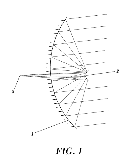
5 Figure 1; shows a side view of an embodiment of the invention in which the
detector is placed behind the primary mirror.
Figure 2; shows an aerial view of another embodiment of the invention in
which the detector is placed between the two mirrors.
Figure 3; shows a side view of an embodiment of the invention that uses a
beam splitting device to split the beam into two with orthogonal
polarisations.
Figure 4; shows a side view of a possible mechanical assembly for the
embodiments in figures 1 and 2.
Figure 5; shows a side view of an embodiment of the invention that radiates
the object plane and simultaneously detects the radiation from the object
plane,
following the same scan pattern, and in accordance with figure 1.
Figure 6; shows a side view of another possible mechanical assembly for this
invention in accordance with figure 1 or 2.
DESCRIPTION OF THE INVENTION
Figure 1 shows an embodiment of the invention in which a detector is placed
behind the primary mirror. The primary mirror (1) is concave, while the
secondary
mirror (2) is convex. The radiation focuses on the axis behind the primary
mirror at
the focus (3) where the detector is located. This embodiment, without being
considered as a restriction to the invention, is designed to facilitate the
integration of
a single pixel detector and / or a radar transceiver or a LADAR or LIDAR
system.
Figure 2 shows an embodiment of the invention in which a detector is placed
between the two mirrors. In this case the primary mirror (1) is concave and
the
secondary mirror (2) is plane. This other possible embodiment is designed for
a
system that uses a line of detectors and their corresponding antennae. By
placing a
line of detectors in the focal plane, the system covers a field of view (in
the same
direction) proportional to the length of this line of detectors, despite the
fact that the
drawing only represents the ray trace that corresponds to the central antenna
and
CA 02780162 2012-04-13
WO 2011/045087 PCT/EP2010/053558
6
the two antennae at either end of the line. Simultaneous, alternative or
successive
detection channels can be used.
Figure 3 shows an embodiment of the invention that uses a beam splitting
device to split the beam into two with orthogonal polarisations. This case is
an
example of the embodiment described in figure 1, but it could also be applied
to the
embodiment described in figure 2. The primary mirror is (1), the secondary
mirror is
(2). When the radiation reaches the beam splitter (e.g. linear polariser 5),
this filters
one electric field component (that represents approximately 50% of the energy)
and
rejects the orthogonal component. By placing the two antennae (4) and (6) with
orthogonal polarisations, the highest amount of energy from each point of the
scanned scene is integrated and consequently the thermal sensitivity in the
image is
improved. Another example, without limiting the invention, is to use one or
several
devices that separate the beam by filtering radiation of a specific wavelength
(for
e.g. millimetre-wave), and reflecting radiation corresponding to another
wavelength
(for e.g. infrared), in order to subsequently redirect each of the different
beams to
different detectors and thus form multispectral images.
Figure 4 shows a possible mechanical assembly for the optics shown in
figures 1 and 2, without being considered a restriction to the invention. The
primary
mirror (1) has a rotation axis (13) and a normal to its surface (15). The
secondary
mirror (2) also has a normal (14) and a rotation axis which is aligned with
the
primary mirror's axis (13). In this case both mirrors (1 and 2) are
mechanically
enslaved via a set of transmission gears (9). The coupling to the motor (17)
can be
done either directly or via a first stage of the transmission at 909 with
respect to the
motor axis. In the following stage a crown gear (10) is rotated, which in turn
transmits the rotation to another two crown gears (11 and 12) perpendicular to
(10).
Each of these gears is fixed to an axis, at the other end of which another
crown gear
is attached, which is the one that transmits the rotation to each of the
rotating
mirrors. Thus, only one motor is needed. An important advantage is that this
embodiment allows for the detector/s to be placed both in between the two
mirrors
and behind the primary mirror (1), as long as a central aperture is machined
in the
mirror.
CA 02780162 2012-04-13
WO 2011/045087 PCT/EP2010/053558
7
Figure 5 shows an embodiment of the invention incorporating the
arrangement in figure 1. This embodiment is designed to radiate the object
plane
and simultaneously detect the radiation (emitted and reflected) from the
object
plane, following the same scan pattern.
In this case the output of an artificial source (22) is placed in the focal
plane
from where it radiates the secondary mirror (2), that reflects radiation
towards the
primary mirror (1) where radiation is reflected towards the object plane (20)
and
distributed following a scan pattern given by the inclination of both mirrors.
This
radiation is reflected when it reaches the object (21) at the object plane
(20). The
scanning system is also provided with a detector (23) in the focal plane close
to the
artificial source.
DESCRIPTION OF A PREFERRED EMBODIMENT OF THE INVENTION
A preferred embodiment is shown in Figure 6. The primary mirror (1) has a
rotation axis (13) and a normal to its surface (15). The secondary mirror (2)
also has
a normal (14) and a rotation axis which is aligned with the primary mirror's
axis (13).
Both mirrors (1 and 2) are electronically synchronised as each is coupled to a
motor
that rotates them (6 and 5) and has a positioning sensor. Thus the device that
governs the movement of the motors is able to detect and correct possible
deviations in the synchronism. The primary mirror (1) is attached to a
structure
containing a bearing (26). This structure (19) is connected to the chassis
(16), and
includes a hole aligned with the bearing and the hole of the primary mirror,
to allow
the positioning of the detector and/or emitter everywhere along optical axis.
The
rotation of motor (6) is transmitted to mirror (1) through a transmission belt
(25). The
secondary mirror (2) is supported by means of a bearing and coupled directly
to a
motor (5). This motor is held by a metallic structure (27), and a non-metallic
structure (18) connects structure (27) with the chassis (16).
In this text, the term "comprises" and its derivations (such as "comprising",
etc.) should not be understood in an excluding sense, that is, these terms
should not
be interpreted as excluding the possibility that what is described and defined
may
include further elements, steps, etc.
CA 02780162 2012-04-13
WO 2011/045087 PCT/EP2010/053558
8
On the other hand, the invention is obviously not limited to the specific
embodiment(s) described herein, but also encompasses any variations that may
be
considered by any person skilled in the art (for example, as regards the
choice of
materials, dimensions, components, configuration, mechanical design, etc.),
within
the general scope of the invention as defined in the claims.