Note: Descriptions are shown in the official language in which they were submitted.
CA 02780285 2012-05-08
WO 2011/054124 PCT/CH2010/000280
- 1 -
MEDICAL DEVICE, APPARATUS, AND SURGICAL METHOD
FIELD OF THE INVENTION
The invention is in the field of medical technology. In particular, it relates
to medical
devices, medical apparatus and medical methods, especially to implants,
apparatuses
for implantation, and implantation methods.
BACKGROUND OF THE INVENTION
If screws are anchored in live bone tissue of the vertebrae, often the problem
of
insufficient bone stability or insufficient stability of the anchoring in the
bone arises.
Especially, in trabecular bone tissue, any load acting on the screw is passed
over to
only few trabeculae, with adverse consequences both for the load bearing
capability
of the screw-bone connection and for its long-time stability. This is
especially severe
in osteoporotic or osteopenic or otherwise weakened vertebral bone tissue.
An important group of screws anchored in the vertebral bone tissue are pedicle
screws. Pedicle screws comprise a screw head for being affixed to a rod or
other
spine stabilizing device and a threaded screw shaft to be implanted in the
vertebra
from a dorsal direction through the pedicle so that it protrudes into the
vertebral
CONFIRMATION COPY
CA 02780285 2016-12-08
- 2 -
body. Pedicle screws are thus part of a stabilization arrangement of the
vertebral
column, and they therefore are subject to substantial mechanical loads.
SUMMARY OF THE INVENTION
In accordance with an aspect of at least one embodiment, there is provided a
pedicle
anchor device for being implanted in a human or animal vertebra from a
generally
dorsal direction through one of the pedicles of the vertebra so that a distal
portion of
the anchor device protrudes into the vertebral body of the vertebra, the
pedicle
anchor device comprising a device body with a proximal head portion for
securing an
orthopaedic device for stabilizing the spinal column, and with a distal shaft
portion
capable of being anchored in the vertebra, the device body further comprising
a
longitudinal bore extending distally from a proximal end, and at least two
holes from
the longitudinal bore outward, the pedicle anchor device further comprising a
liquefiable element that is insertable or inserted in the longitudinal bore
and at least
partly liquefiable by the impact of energy impinging from the proximal side so
that
liquefied material flows through the at least two holes and out of the
longitudinal
bore into structures of at least one of hard tissue and hard tissue
replacement
material, wherein the distal shaft portion is not threaded and has a non-
circular cross
section, and the distal shaft portion is helically twisted with a twist of
between 10
and 270 over an entire length of the distal shaft portion, and wherein at
least a
portion of the distal shaft portion is flat defining two flat sides, and
comprises at least
two of the holes from the longitudinal bore outward, one hole being arranged
in each
flat side.
In accordance with a first aspect of the invention, a pedicle anchor device is
provided. The pedicle anchor device is equipped for being used like a pedicle
screw,
i.e. for being implanted in the vertebra from dorsal direction (but generally
at an
CA 02780285 2016-12-08
- 2a -
angle to the sagittal plane, slightly inward towards the sagittal plane)
through the
pedicle so that a distal portion of the device protrudes into the vertebral
body. The
pedicle anchor device comprises a pedicle anchor device body. A proximal
portion of
the pedicle anchor device body has a head portion that serves for securing an
orthopaedic rod or other device that stabilizes the spinal column. The pedicle
anchor
device body thus has a head portion and a shaft portion. The head portion and
the
shaft portion may be of one piece, or the head portion may be connected to the
shaft
portion by a multi-axial or other connection. The shaft portion is capable of
being
anchored, like a pedicle screw shaft (sometimes referred to as `stem'), in the
vertebra. The head portion may for example be formed like head portions of any
prior art pedicle screws, or may be formed in accordance with the
specifications of a
new spine stabilizing system. The main requirement of the head portion is that
it
serves for either directly being affixed to a rod or other spine stabilizing
device or for
being affixed to an intermediate device to which a rod (or other spine
stabilizing
device and/or other intermediate device) can be affixed.
CA 02780285 2016-12-08
- 3 -
The pedicle anchor device body according to the first aspect of the invention
further
has a longitudinal bore that extends from a proximal end of the pedicle anchor
device
body and has a hole or a plurality of holes from the longitudinal bore
outward, for
example radially outward.
5 Further, the pedicle anchor device comprises a liquefiable element that
is insertable
or inserted in the longitudinal bore and at least partly liquefiable by the
impact of
energy impinging from the proximal side so that liquefied material flows
through the
holes in the wall and out of the longitudinal bore into structures of the hard
tissue
and/or hard tissue replacement material. Thereby, after solidification of the
10 liquefiable (preferably thermoplastic) material, the an anchoring of the
positive-fit
connection kind is achieved in the hard tissue/hard tissue replacement
material.
The liquefiable element may be a single, one-piece element. Such a single one-
piece
element may be advantageous in terms of transmitting mechanical energy from a
proximal to a distal end. Alternatively, a plurality of liquefiable elements
may be
= 15 present, such as a plurality of shaped pieces, chips,
flakes, etc.
The principle liquefying, by the impact of mechanical energy, material in a
sleeve
element (in this text, we refer to sleeve element or tube element or sheath
element
generally to mean an element with a longitudinal bore with openings ranging
from
the bore to an outside, without restriction to a particular outer shape) with
lateral
20 openings and of pressing liquefied material out of the sleeve element
with lateral
openings is for example described in US 7,335,205, US 6,921,264,
WO 2009/055 952, WO 2009/010247, WO 2009/010234, and PCT application No.
PCT/CH 2009/000138.
CA 02780285 2012-05-08
WO 2011/054124
PCT/CH2010/000280
- 4 -
In a first group of embodiments, the pedicle anchor device is a pedicle screw,
wherein the shaft is threaded.
In some embodiments of the first group of embodiments, the thread has a
constant
outer diameter (major diameter), whereas a core diameter (minor diameter) is
larger
at the proximal side than at the distal side. For example, the core diameter
may be
gradually reduced along the entire length of the threaded section, or the core
diameter has a stepped characteristics, or has any other characteristics. In
other,
alternative embodiments, the core diameter is constant.
In the embodiments of the first group of embodiments, anchoring is achieved by
a
combination of the effect of the thread and the effect of the liquefiable, re-
solidified
material interpenetrating structures of the hard tissue/hard tissue
replacement
material.
In accordance with a second group of embodiments, the shaft of the pedicle
anchor
device is not threaded.
In these embodiments, the shaft may have a non-circular cross section. For
example,
the shaft may be flattish so as to be blade-like. Especially, the shaft may be
such as to
have, where it penetrates the pedicle, a larger longitudinal than transversal
extension
such as to follow the pedicle's shape. In an example, the shaft may be at an
acute
angle to the transverse plane so that the larger extension perpendicular to
the
proximodistal axis is in the direction approximately corresponding to the
corresponds
direction of the larger extension of the pedicle (in section perpendicular to
the
proximodistal axis).
CA 02780285 2012-05-08
WO 2011/054124
PCT/CH2010/000280
- 5 -
A non-circular cross section may in addition if necessary provide additional
stability
against twisting movements.
In special embodiments, the shaft may have a non-circular cross section and
may be
twisted. Such a twist brings about an improved effective anchoring cross
section:
larger and other portions of the tissue may contribute to the anchoring.
If the shaft is twisted, generally non-zero twists up to 2700 are preferred,
since up to
about 270 the orientation within the pedicle may approximately use the space
available within the pedicle, whereas much stronger twists would lead to the
anchor
device being substantially twisted within the pedicle so that the dimension of
largest
extension of the shaft would have to be adapted to the smaller cross sectional
extension of the pedicle (in cross section perpendicular to an implantation
axis).
More in general, a preferred range for the twist of the pedicle anchor device
over its
entire length may be between 10 and 270 .
For example, the shaft may be twisted into about a quarter of a helix,
especially by
about 80 -120 , so that a blade plane at the distal end is approximately
perpendicular
to a blade plane at the proximal end of the shaft. For example, a rod
receiving head
portion (or other means for affixing a spinal column stabilizer) may be
oriented
relative to the twisted shaft so that the blade plane at the proximal end of
the shaft is
oriented approximately parallel to a longitudinal direction and at the distal
end of the
shaft is oriented approximately parallel to a transversal direction (these
terms of
direction are to be understood to apply locally, referring to a spine axis).
By this
special configuration, it is possible to provide a comparably large cross
section shaft
that anchors well without the relatively small transversal extension of some
pedicles
without overly limiting the cross section of the shaft. In addition, the
pedicle anchor
device may extend transversally in the vertebral body so as to provide
superior
CA 02780285 2012-05-08
WO 2011/054124
PCT/CH2010/000280
- 6 -
-
stability especially against angular momenta acting on the anchor that cause
longitudinal (up and down) forces on the distal end of the anchor and that
often arise
during body movements of the patient.
In embodiments of the second group of embodiments where the shaft does not
have a
circular cross section, the shaft may be slightly tapered to add a press fit
effect to the
anchoring effects achieved by the mere shape and by the liquefied and re-
solidified
material.
In embodiments of the second group of embodiments where the shaft does not
have a
circular cross section but is flattish, the holes from the longitudinal bore
outward
may especially include openings on each of the two flat sides. Additional
holes on at
least one of the small sides and/or at the distal end may be present. An
additional,
axial hole at the distal end may be advantageous during surgery because it
allows
guidance of the anchor during insertion by means of a K wire or similar
device. Such
an axial hole may be arranged in the center (with respect to the axis) or off-
center.
Depending on the parameters 'hole diameter' and 'hole depth, (also in relation
to the
according parameters of the other hole(s) along the circumference), the axial
hole
may be such that liquefied material is pressed out through the hole into the
tissue, or
that the liquefied material that gets into the axial hole freezes before it
reaches the
hole exit so that a plug of the liquefiable, re-solidified material is
created.
The invention also concerns a method of implanting a pedicle anchor device
according to the second aspect by a method having at least one method step of
the
method described referring to the figures. Especially, a method of anchoring a
pedicle anchor device may comprise the steps of inserting a pedicle anchor
device
body of a pedicle anchor device of the described kind into a vertebra, of
pressing a
liquefiable element in the longitudinal bore towards the distal side while
coupling
CA 02780285 2012-05-08
WO 2011/054124
PCT/CH2010/000280
- 7 -
energy into the liquefiable element, of thereby causing portions of the
liquefiable
element to be liquefied and pressed out of the at least one hole into bone
tissue, and
of causing the liquefied portions to re-solidify to provide an additional
anchor.
If the pedicle anchor device has an outer shape that is not purely cylindrical
but has
an outer retention structure, such as a thread, or is helically twisted, the
pedicle
anchor device is anchored by such a structure. An additional anti-rotation
protection
possibly required for this anchoring if self-locking is not sufficient may for
example
be naturally provided by a spine stabilizing rod or similar. Depending on the
situation, the surgeon may be free to use a liquefiable element for ensuring
an
additional anchoring strength ¨ or he may choose to not use liquefiable
material if
she/he feels that the anchoring strength is sufficient.
In preferred embodiments, the pedicle anchor device is a device according to
an
embodiment of the first aspect of the invention.
Anchor devices of the above-described kind with a non-circular shaft portion
extending from a proximal end and at least one hole from the longitudinal bore
outward (and, if necessary, with a head portion proximal of the shaft portion)
may
also be provided for other applications than as pedicle screws. The shaft of
such
anchor devices may optionally be helically twisted, for example by 90 as the
above-
described pedicle anchor device.
Especially, such an anchor device may be used as anchor for the treatment of
fractures, especially fractures close to joints where the bone tissue is
sometimes
comparably weak and where it may difficult to anchor conventional surgical
screws.
CA 02780285 2012-05-08
WO 2011/054124
PCT/CH2010/000280
- 8 -
In order to investigate advantages of the anchoring of a Ti implant using
thermoplastic material in comparably weak bone tissue, calculations and
experiments
were made. Finite Element calculations have been performed for anchors that
comprise a Ti core with a rectangular cross section and thermoplastic material
that is
liquefied by mechanical energy and pressed into structures of surrounding
tissue to
form, after re-solidification, an anchor. These calculations have revealed ¨
for the
example of the anchoring of a pedicle screw ¨ a substantial reduction of the
stress.
The van Mises strain has been shown to be reduced by between 74.5% for anchors
of
a circular cross section and 87% for anchors of an H shaped cross section (M.
Rollinghoff and S. Saladin, ETH Zurich Master Thesis). This finding was
experimentally confirmed by biomechanical experiments on a human Calcaneus.
For
this, a Schanz screw was compared to a pin-shaped Titanium anchor (core
diameter:
4 mm) that was coated by 0.5 mm PLDLA 70/30 and anchored with the aid of
mechanical vibrations causing the PLDLA to be at least partly liquefied and
pressed
into structures of the spongy bone to provide an anchoring therein. The
pullout force
was measured (over a 2 mm indenter) as a function of the hardness (indentation
resistance) of the spongy bone. The pullout force of the coated Ti anchor was
significantly superior to the pullout force of the Schanz screw by a factor 2-
4, the
difference being greater for weak bone tissue.
Also, pullout failure measurements were made using a pedicle screw of the kind
depicted in Figures 3-5 from cadaveric osteopenic human vertebrae, and for
comparison a pedicle screw with a same shape but without thermoplastic
material
pressed out of radial the holes. The failure force for permanent dislocation
was
shown to be raised by an average of 124%. A further important finding was a
massive improvement of the loosening behaviour of the pedicle screw with
thermoplastic material anchoring that was observed as a deviation from the
elastic
behaviour.
CA 02780285 2012-05-08
WO 2011/054124
PCT/CH2010/000280
- 9 -
In embodiments that may be embodiments of the first or the second group, the
material of the liquefiable element(s) may contain an additional substance,
for
example for promoting healing or regeneration of for furthering x-ray
visibility. For
example, the additional substance may be a growth factor, an antibiotic, an
inflammation inhibitor or a buffer. More particularly, the additional
substance be a drug
promoting healing, in particular growth, differentiation and/or regeneration
such as a
proteinaceous drug like a growth and/or differentiation factor, e.g. of the
Bone
Morphogenic Protein family (especially BMP 2, 6, 7, for certain applications
also
BMP 12, 13), an Insulin Growth Factor (e.g. IGF 1), a Platelet Derived Growth
Factor (PDGF), a Growth and Differentiation Factor (e.g. GDF 5) etc. and also
combinations thereof and/or other an other drug including a non-proteinaceous
drug
including small molecules (e.g. biphosphonates), possibly in combination with
a
proteinaceous drug, etc..
In embodiments that may be embodiments of the first or the second group, the
liquefiable element(s) may be of a hydraulic cement (such as a polymeric or
other
hydraulic cement) with thixotropic properties. Such embodiments may be
embodiments
in which the liquefiable material comprises an additional substance, such as a
growth
factor.A special example of an anchor device is a device for treatment of a
fracture of
a neck of a femur where it can replace a state-of-the-art nail that penetrates
from the
shaft of a femur into its head through the fractured neck, for example in a
position
and orientation as disclosed in US 3,025,853.
More generally, such an anchor device may be used as stabilizing screw in
situations
where anchoring in the human or animal bone is difficult and/or where the
geometrical restrictions and/or the mechanical load to be borne make a non-
circular
cross section and for example even twisted shaft advantageous.
CA 02780285 2012-05-08
WO 2011/054124
PCT/CH2010/000280
- 10 -
In embodiments, the anchor device body comprises a plurality of holes from the
longitudinal bore to the outside, and the anchor device comprises a directing
structure structured angularly with respect to a longitudinal axis of the
longitudinal
bore to direct different portions of the liquefiable material to different
ones of the
holes. 'Structured angularly' ¨ or azimuthally ¨ means that the structure is
not
constant along the circumference but varies as a function of the azimuthal
angle. In
this, the directing structure is a structure within the cross section of the
longitudinal
bore, i.e. if, for example, the longitudinal bore has a circular cross
section, the
directing structure's radial position is at least partly within the radius of
the bore.
The directing structure is then formed by a stop face, against which the
distal end of
the liquefiable element is pressed during liquefaction. The distal stop face
for the
liquefiable element may for example close off the longitudinal opening towards
the
distal side or at least substantially reduce (by for example at least 50%) a
distal
portion of the longitudinal opening's cross section compared to the proximal
portion.
An optional, remaining cross section of the longitudinal opening distal
portion
extending distally from the directing structure may for example serve as a
central
guiding portion or as distal hole through which liquefied material portions
may be
pressed out in addition to the holes in wall of the sheath element. The stop
face may
be formed by the anchor device body. Alternatively, the directing structure is
a
directing structure of an insert element that is insertable in situ.
In accordance with a further, second aspect of the invention, a method of
augmenting hard tissue and/or hard tissue replacement material for insertion
of an
implant, and an implantation method including such an augmenting method are
provided. The implant has an enossal region that after implantation will be
anchored
in the hard tissue and/or hard tissue replacement material. A profile body as
used for
the fourth aspect of the invention has a portion the outer profile of which
essentially
corresponds to the outer profile of at least a part of the implant's enossal
region.
CA 02780285 2012-05-08
WO 2011/054124
PCT/CH2010/000280
- 11 -
Specifically, the implant may have an outer thread, and the profile body then
has an
outer thread with same thread parameters (such as thread pitch etc.) and same
dimension, except that the profile body's extension may optionally be smaller,
preferably only to a small extent, than the corresponding extension of the
implant. It
is also possible that the minor diameter of the thread is essentially
identical between
the implant and the profile body, whereas the major diameter of the profile
body's
thread is smaller than the major diameter of the implant's thread.
The profile body further comprises a longitudinal bore reaching distally from
a
proximal end of the profile body. At least one hole is in the wall surrounding
the
longitudinal bore. A liquefiable element may be introduced into the
longitudinal bore
or is present therein. The profile body further comprises a stop face for the
liquefiable element against which a distal end of the liquefiable element may
be
pressed. The profile body is thus a sheath element of the hereinbefore
described kind.
It may optionally ¨ but not necessarily ¨ be formed according to embodiments
of the
first aspect of the invention. As the case may be, in addition to the profile
body an
insert element may be present.
The method according to the second aspect then features the additional steps
of:
-
introducing the profile body into an opening or gap in the hard tissue and/or
hard tissue replacement material;
- pressing the liquefiable element against the distal stop face while energy
impinges on it to cause material of the liquefiable element to be liquefied,
to
be pressed through the at least one hole, and to be pressed into structures of
CA 02780285 2012-05-08
WO 2011/054124
PCT/CH2010/000280
- 12 -
the bone tissue or other hard tissue or hard tissue replacement material in
which the implant will be anchored, to yield a pre-shaped augmented region;
- removing the profile body; and
- inserting the implant so that a contour of the pre-shaped augmented
region
cooperates with an outer profile of the implant to secure the implant against
undesired movements.
Prior to the step of removing the profile body, other steps may be made. For
example, the profile body may replace a trial implant, and an x-ray (or other)
control
of the position and/or other conditions may be made. By this combination the
functional ities of the profile body for augmentation and a trial implant, the
augmentation process according to the aspect of the invention brings about
only few
extra steps compared to prior art methods without augmentation.
Generally, the feature that the outer profile of a section of the profile body
essentially
corresponds to the outer profile of at least a part of the implant's enossal
region does
not imply that all dimensions in said sections are equal. Rather, the
dimensions of the
profile body may be different, especially they may be smaller. The feature
implies
however that the shape of the implant coarsely fits into a space moulded using
the
profile body in that for each profile feature (i.e. feature that protrudes
from a convex
basic body such as a cylindrical basic shape) of the implant, there exists a
corresponding feature of the profile body, and the profile features of are in
an
corresponding positional relationship to each other. In the case the implant
comprises
an outer thread, this implies that the profile body also comprises an outer
thread, with
a same thread pitch (this does not exclude multiple threads of the implant and
CA 02780285 2012-05-08
WO 2011/054124
PCT/CH2010/000280
- 13 -
accordingly of the profile body). In case the implant comprises a plurality of
axial
tongues, at defined azimutal angles, the profile body will comprise a
corresponding
number of axial tongues at same azimuthal angles, etc.
If the profile body is smaller than the implant, the dimensions will
preferably vary
only slightly. For example, if the implant has a thread, the minor diameter of
the
thread is for example smaller by at most 5% and is preferably equal. The
thread
depth of the profile body thread is preferably at least 50% of the thread
depth of the
implant thread depth.
Often, prior art anchoring of implants such as of bone screws has been
confronted
with the problem that especially the cancellous bone tissue contributed little
to the
anchoring stability. This is because cancellous bone tissue may tend to be
brittle, and
only few trabeculae may contribute to withstanding tearing forces. If the
tissue is
augmented by, for example, thermoplastic material filling structures within
the
trabeculae, this problem may at least partly be solved. However, if the
thermoplastic
material is sufficiently ductile and tough, considerable forces are necessary
to screw
a self-tapping thread or a separate tapper into the augmented tissue. Often,
there is a
danger that an augmentation material body comprising the augmentation material
and a few trabeculae embedded in the augmentation material breaks loose from
the
cancellous bone tissue and is rotated as a whole in the tissue.
The approach according to the second aspect of the invention, in contrast,
makes
possible that even implants with pronounced profile features ¨ such as screws
with
comparably large thread depths ¨ may be inserted in augmented tissue/material
that
is comparably very stable and resistive to forces without having to excerpt,
during
introduction, too high forces.
CA 02780285 2012-05-08
WO 2011/054124
PCT/CH2010/000280
- 14 -
Embodiments of the method according to the second aspect of the invention may
be
viewed as moulding an augmented region anchored in the hard tissue and/or hard
tissue replacement material to a desired shape for the implant to be
introduced in a
later step.
A subsequent forming step that includes the removal and/or deformation of
material
is thus not necessary (though the second aspect of the invention does not
exclude an
additional forming step). The approach according to the second aspect of the
invention may make a gentle but effective augmentation possible.
In embodiments, the profile body is chosen to have between three and five
holes in
the wall around the longitudinal bore, the holes being at approximately equal
axial
positions. For example the profile body may be chosen to have exactly four
holes in
the wall around the longitudinal bore, the holes being at approximately equal
axial
positions.
In embodiments, the profile body may have an angularly structured directing
structure distally of the longitudinal bore to direct different portions of
the
liquefiable/liquefied material to different ones of the openings.
In embodiments, the profile body has a profile essentially corresponding to at
least a
section of the enossal portion of a pedicle screw. The method then comprises
introducing the profile body, from an essentially dorsal direction, through
into the
vertebra, and more particularly into the pedicle. The implant implanted
subsequently
to augmenting is then a pedicle screw.
CA 02780285 2012-05-08
WO 2011/054124
PCT/CH2010/000280
- 15 -
A kit of parts for carrying out an implantation according to the second aspect
of the
invention comprises the profile body and the implant (for example pedicle
screw). It
may further comprise the liquefiable element.
In accordance with a third aspect of the invention, an anchoring device, such
as a
surgical screw, is provided, the anchoring device comprising an anchoring
device
body with a longitudinal bore that extends from a proximal end of the
anchoring
device body and has a hole or a plurality of holes from the longitudinal bore
outward,
for example radially outward. The anchoring device further comprises a
material that
can be brought from a flowable state to a non-flowable state, the material for
example being thermoplastic or a hydraulic cement with or without thixotropic
properties. If the material is a thermoplastic, then the bringing from a
flowable to a
non-flowable state may merely comprise a letting the previously (fully or
partially)
melted material cool. If the material is a cement, the bringing from a
flowable to a
non-flowable state may comprise a hardening the cement. If the material is
thixotropic material, the bringing from a flowable to a non-flowable state may
comprise a causing the source of the shear stress to stop and to thereby
enhance the
viscosity.
In accordance with this aspect, the material further comprises an additional
substance
that may be a drug promoting healing, in particular growth, differentiation
and/or
regeneration such as a proteinaceous drug like a growth and/or differentiation
factor,
e.g. of the Bone Morphogenic Protein family (BMP 2, 6, 7; 12, 13)/the
transforming
growth factor beta family, an Insulin Growth Factor (e.g. IGF 1), a Platelet
Derived
Growth Factor (PDGF), a Growth and Differentiation Factor (e.g. GDF 5) etc.
and
also combinations thereof and/or other an other drug including a non-
proteinaceous
drug including small molecules (e.g. biphosphonates), possibly in combination
with a
proteinaceous drug, etc.
CA 02780285 2012-05-08
WO 2011/054124
PCT/CH2010/000280
- 16 -
The anchoring device body is of a material that is not liquefiable under
implantation
conditions. It may be made of a metal, of a ceramic, of a (potentially
reinforced)
plastic that does not liquefy under implantation conditions, or of an other
suitable
biocompatible material. Further, the anchoring device body preferably has an
anchoring structure, especially a thread. Especially, the anchoring device
body may
be a surgical screw, especially a pedicle screw.
The third aspect may be combined with the first aspect (especially the first
group of
embodiments) of the invention.
The third aspect thus proposes to provide a surgical screw (or similar
anchoring
device) with a material that comprises a drug promoting healing, which
material can
be pressed out of the opening(s) from the longitudinal bore outward into the
surrounding tissue, especially into cancellous bone tissue. Thus by the
method/device
in accordance with the third aspect, it becomes readily possible to combine
the
function of a surgical screw, with brining the healing promoting drug directly
into
the bone tissue. The material that can be pressed out of the opening(s) has an
additional anchoring effect and especially may provide a substantial
improvement of
the loosening behaviour.
An special class of (matrix) materials in which the additional substance may
be
embedded is hydraulic cements that are resorbable and/or osteoconductive. A
special
class of cements is calcium phosphate cements, for example based on Ca4(PO4)20
and CaHPO4 powders mixed with water. Such substances may harden at physiologic
conditions. Calcium phosphate cements may harden by ion exchange in the human
body; calcium phosphate cements exist that have some stability of a non-
hardened
phase at room temperature but that harden quickly at body temperature.
CA 02780285 2012-05-08
WO 2011/054124
PCT/CH2010/000280
- 17 -
Specific examples of suitable Calcium Phosphate Cements are `ChronOS' and
`Norian' by Synthes.
A further example are not resorbable cements like PMMA cements.
In addition to the drug that promotes healing, the material may comprise a
polymer
and/or a hydrogel.
If the (matrix) material is a hydraulic cement, mechanical energy, such as
mechanical
vibrations, may impinge on the material while the material is driven out of
the
opening(s). Especially, an effect of thixotropy may help to reduce the
viscosity so
that the driving out of the opening(s) is possible with less force acting on
the material
from the proximal side.
An other special class of (matrix) materials in which the additional substance
may be
embedded is resorbable thermoplastic polymers such as the resorbable polymers
mentioned hereinafter. Further suitable examples are mixtures of any
combination of:
- one or more hydraulic cement(s);
- one or more for example resorbable polymer(s);
- one or more hydrogel(s).
CA 02780285 2012-05-08
WO 2011/054124
PCT/CH2010/000280
- 18 -
In accordance with the prior art, a damaged bone tissue part is treated by
filling a
hole or similar by bone cement (that may be provided with growth factors). In
contrast thereto, the approach according to the sixth aspect of the invention
makes
possible a much more targeted treatment wherein the drug, by being pressed out
of
the opening(s), is applied directly to the interior of the bone tissue, has a
more
intimate contact therewith, and less or no other tissue than the bone tissue
is exposed
to the drug.
- A
further use of bone growth factors (or other additional substance with a
clinical effect, especially of the above-described kind) is the following:in a
first step, a hydraulic cement comprising a bone growth factor (or other
additional substance) is pressed out of the longitudinal bore of a device body
of the kind with a longitudinal bore and one or more holes from the bore
outward,
- in a second, subsequent step a thermoplastic element is at least partially
liquefied by the impact of mechanical energy, and liquefied portions are
pressed out of the hole(s) through which the hydraulic cement had been
pressed out.
This sequence of method steps may be used in any aspect of the invention that
features using the thermoplastic material for augmenting or anchoring and may
be
used in any aspect of the invention that features the hydraulic cement as
(matrix)
material comprising a drug promoting healing. Alternatively, it may be applied
independently of the other aspects described herein. It has the following
purposes/effects:
CA 02780285 2012-05-08
WO 2011/054124
PCT/CH2010/000280
-19-
- acceleration of the healing process, improvement of the bone densitiy
- immediate stabilization, prevention of early loosening that would
otherwise
mechanically prevent osseous consolidation of the implant, e.g.
osseointegration.
Since the polymer is quenched and since the heat capacity and heat
conductivity of
the polymer are much smaller than of the aqueous environment, no thermal
damage
of the active component in the cement may be expected due to this procedure.
In addition to the above described aspects, the invention features the
following
additional aspects:
- The use of a body with a longitudinal bore that extends from a proximal end
of the body and has a hole or a plurality of holes from the longitudinal bore
outward, and mechanical vibrations that by a thixotropc effect reduce the
viscosity to administer a hydraulic cement to bone tissue, for example for
anchoring, drug delivery, and/or other purposes.
- Liquefaction, by mechanical vibrations, of polymer particles dispensed
within
a hydraulic cement, for example to influence the viscosity of the
heterogeneous mixture, for example for administering the mixture to tissue,
for example by pressing it out of a hole a body with a longitudinal bore that
extends from a proximal end of the body and has a hole or a plurality of holes
from the longitudinal bore outward.
CA 02780285 2012-05-08
WO 2011/054124
PCT/CH2010/000280
- 20 -
-
Liquefaction of a hydraulic cement in combination with a stabilizing polymer
phase with a solvent for the polymeric phase and using the replacement of the
solvent by water to harden the polymeric phase and thereby the cement.
Example: N-Pyrrolidone.
- Using a tube
element of a thermoplastic polymer, such as a resorbable PLA,
to hold a liquid cement mixture (such as a cement powder dispersed in
water), then using mechanical energy (such as mechanical vibrations) to
liquefy the thermoplastic polymer, for example in contact with bone tissue, so
as to release the cement mixture into surrounding bone tissue, whereafter it
may harden.
In all these aspects, the not liquefiable body (if present) may be a surgical
screw with
a longitudinal bore, especially a pedicle screw.
All these additional aspects except the last aspect may be combined with the
third
aspect of the invention and may further be combined with other aspects of the
invention. Further, the additional aspects except the last aspect may be
combined
with each other. The last of the additional aspects may be combined with
providing
an additional substance in the material, which additional substance may be a
drug,
such as any one of the above-mentioned drugs.
Embodiments of devices and methods in accordance with all aspects of the
invention
may be devices/methods for human surgery, or alternatively for (non-human)
animal
surgery, especially for surgery of dogs, cats or other pets.
CA 02780285 2012-05-08
WO 2011/054124
PCT/CH2010/000280
- 21 -
In embodiments of the aspects of the invention, the holes through which the
liquefied
material flows out during implantation/augmentation, may be on a same axial
position, or they may be at different axial positions. The angular positions
may be
evenly distributed around the circumference. In special embodiments, the
angular
positions may have a deviating distribution adapted for a particular need. For
example, if the implant is destined to be an implant for fusing joint parts,
and for
being inserted in a joint space, the holes (if more than two) may be
concentrated on
opposed sides to be in contact with the joint areas.
In special embodiments of any aspect of the invention or of any other
anchoring or
augmentation process that includes pressing liquefied material out of holes in
a
sheath element, a multi-tiered anchoring or augmentation may be made, with
sequentially anchoring/augmenting in different tiers, to each tier being
attributed at
least one outflow hole (and preferably a plurality of outflow holes). To this
end, after
anchoring/augmenting on a first tier, an insert element (which may be a first
insert
element if the sheath element itself comprises a distal stop face or which may
be a
second insert element if for the anchoring/augmentation at the first tier
already an
insert element was used) is inserted from the proximal side and caused to stop
at a
position immediately underneath the second tier. Then, again a liquefaction
process
is initiated. This may optionally be repeated for a third, or even a fourth,
fifth, etc.
tier.
In embodiments where the implant does not have a thread, the outer shape of
the
implant (and/or of the augmentation device) does not need to be generally
circularly
cylindrical but may have any contour.
Mechanical vibration or oscillation suitable for devices and methods according
to
embodiments of the invention that include liquefaction of a polymer by
friction heat
CA 02780285 2012-05-08
WO 2011/054124
PCT/CH2010/000280
- 22 -
created through the mechanical vibration has preferably a frequency between 2
and
200 kHz (even more preferably between 10 and 100 kHz, or between 20 and 40
kHz)
and a vibration energy of 0.2 to 20 W per square millimeter of active surface.
The
vibrating element (sonotrode) is e.g. designed such that its contact face
oscillates
predominantly in the direction of the element axis (longitudinal vibration)
and with
an amplitude of between 1 and 100 m, preferably around 10 to 30 pm. Rotational
or
radial oscillation is possible also.
For specific embodiments of devices, it is possible also to use, instead of
mechanical
vibration, a rotational movement for creating the named friction heat needed
for the
liquefaction of the anchoring material. Such rotational movement has
preferably a
speed in the range of 10'000 to 100'000 rpm. A further way for producing the
thermal energy for the desired liquefaction comprises coupling electromagnetic
radiation into one of the device parts to be implanted and designing one of
the device
parts to be capable of absorbing the electromagnetic radiation, wherein such
absorption preferably takes place within the anchoring material to be
liquefied or in
the immediate vicinity thereof. Preferably electromagnetic radiation in the
visible or
infrared frequency range is used, wherein the preferred radiation source is a
corresponding laser. Electric heating of one of the device parts may also be
possible.
In this text the expression "thermoplastic material being liquefiable e.g. by
mechanical vibration" or in short "liquefiable thermoplastic material" or
"liquefiable
material" is used for describing a material comprising at least one
thermoplastic
component, which material becomes liquid or flowable when heated, in
particular
when heated through friction i.e. when arranged at one of a pair of surfaces
(contact
faces) being in contact with each other and vibrationally or rotationally
moved
relative to each other, wherein the frequency of the vibration is between 2
kHz and
200 kHz, preferably 20 to 40 kHz and the amplitude between 1 gm and 100 pm,
preferably around 10 to 30 pm. Such vibrations are e.g. produced by ultrasonic
CA 02780285 2012-05-08
WO 2011/054124
PCT/CH2010/000280
- 23 -
devices as e.g. known for dental applications. For being able to constitute a
load-
bearing connection to the tissue, the material at the time of insertion has an
elasticity
coefficient of more than 0.5 GPa, preferably more than 1 GPa. The elasticity
coefficient of at least 0.5 GPa also ensures that the liquefiable material is
capable of
transmitting the ultrasonic oscillation with such little damping that inner
liquefaction
and thus destabilization of the liquefiable element does not occur, i.e.
liquefaction
occurs only where the liquefiable material is at the liquefaction interface to
the stop
face. The plastification temperature is preferably of up to 200 C, between 200
C and
300 C or even more than 300 C. Depending on the application, the liquefiable
thermoplastic material may or may not be resorbable.
Suitable resorbable polymers are e.g. based on lactic acid and/or glycolic
acid (PLA,
PLLA, PGA, PLGA etc.) or polyhydroxyalkanoates (PHA), polycaprolactones
(PCL), polysaccharides, polydioxanones (PD), polyanhydrides, polypeptides or
corresponding copolymers or blended polymers or composite materials containing
the mentioned polymers as components are suitable as resorbable liquefiable
materials. Thermoplastics such as for example polyolefins, polyacrylates,
polymetacrylates, polycarbonates, polyamides, polyesters, polyurethanes,
polysulphones, polyaryl ketones, polyimides, polyphenyl sulphides or liquid
crystal
polymers (LCPS), polyacetals, halogenated polymers, in particular halogenated
polyoelefins, polyphenylene sulphides, polysulphones, polyethers,
polypropylene
(PP), or corresponding copolymers or blended polymers or composite materials
containing the mentioned polymers as components are suitable as non-resorbable
polymers. Examples of suited thermoplastic material include any one of the
polylactide products LR708 (amorphous Poly-L-DL lactide 70/30), L209 or L210S
by Bohringer Ingelheim.
Specific embodiments of degradable materials are Polylactides like LR706
PLDLLA
70/30, R208 PLDLA 50/50, L2105, and PLLA 100% L, all of Bohringer. A list of
CA 02780285 2012-05-08
WO 2011/054124
PCT/CH2010/000280
- 24 -
suitable degradable polymer materials can also be found in: Erich Wintermantel
und
Suk-Woo Haa, "Medizinaltechnik mit biokompatiblen Materialien und Verfahren",
3. Auflage, Springer, Berlin 2002 (in the following referred to as
"Wintermantel"),
page 200; for information on PGA and PLA see pages 202 ff., on PCL see page
207,
on PHB/PHV copolymers page 206; on polydioxanone PDS page 209. Discussion of
a further bioresorbable material can for example be found in CA Bailey et al.,
J Hand
Surg [Br] 2006 Apr;31(2):208-12.
Specific embodiments of non-degradable materials are: Polyetherketone (PEEK
Optima, Grades 450 and 150, Invibio Ltd), Polyetherimide, Polyamide 12,
Polyamide 11, Polyamide 6, Polyamide 66, Polycarbonate,
Polymethylmethacrylate,
Polyoxymethylene, or polycarbonateurethane (in particular Bionate by DSM,
especially Bionate 75D and Bionate 65D; according information is available on
datasheets publicly accessible for example via www.matweb.com by Automation
Creations, Inc.). An overview table of polymers and applications is listed in
Wintermantel, page 150; specific examples can be found in Wintermantel page
161
if. (PE, Hostalen Gur 812, Hochst AG), pages 164 ff. (PET) 169ff. (PA, namely
PA
6 and PA 66), 171 ff. (PTFE), 173 ff. (PMMA), 180 (PUR, see table), 186 ff.
(PEEK), 189 ff. (PSU), 191 ff. (POM ¨ Polyacetal, tradenames Delrin, Tenac,
has
also been used in endoprostheses by Protec).
The liquefiable material having thermoplastic properties may contain foreign
phases
or compounds serving further functions. In particular, the thermoplastic
material may
be strengthened by admixed fillers, for example particulate fillers that may
have a
therapeutic or other desired effect. The thermoplastic material may also
contain
components which expand or dissolve (create pores) in situ (e.g. polyesters,
polysaccharides, hydrogels, sodium phosphates) or compounds to be released in
situ
and having a therapeutic effect, e.g. promotion of healing and regeneration
(e.g.
growth factors, antibiotics, inflammation inhibitors or buffers such as sodium
CA 02780285 2012-05-08
WO 2011/054124
PCT/CH2010/000280
- 25 -
phosphate or calcium carbonate against adverse effects of acidic
decomposition). If
the thermoplastic material is resorbable, release of such compounds is
delayed.
If the liquefiable material is to be liquefied not with the aid of vibrational
energy but
with the aid of electromagnetic radiation, it may locally contain compounds
(particlulate or molecular) which are capable of absorbing such radiation of a
specific
frequency range (in particular of the visible or infrared frequency range),
e.g. calcium
phosphates, calcium carbonates, sodium phosphates, titanium oxide, mica,
saturated
fatty acids, polysaccharides, glucose or mixtures thereof.
Fillers used may include degradable, osseostimulative fillers to be used in
degradable
polymers, including: P-Tricalciumphosphate (TCP), Hydroxyapatite (HA, < 90%
crystallinity; or mixtures of TCP, HA, DHCP, Bioglasses (see Wintermantel).
Osseo-
integration stimulating fillers that are only partially or hardly degradable,
for non
degradable polymers include: Bioglasses, Hydroxyapatite (>90% cristallinity),
HAPEX , see SM Rea et al., J Mater Sci Mater Med. 2004 Sept;15(9):997-1005;
for hydroxyapatite see also L. Fang et al., Biomaterials 2006 Jul; 27(20):3701-
7, M.
Huang et al., J Mater Sci Mater Med 2003 Jul;14(7):655-60, and W. Bonfield and
E.
Tanner, Materials World 1997 Jan; 5 no. 1:18-20. Embodiments of bioactive
fillers
and their discussion can for example be found in X. Huang and X. Miao, J
Biomater
App. 2007 Apr; 21(4):351-74), JA Juhasz et al. Biomaterials, 2004 Mar;
25(6):949-
55. Particulate filler types include: coarse type: 5-20 m (contents,
preferentially 10-
25% by volume), sub-micron (nanofillers as from precipitation, preferentially
plate
like aspect ratio > 10, 10-50 nm, contents 0.5 to 5% by volume).
A specific example of a material with which experiments were performed was
PLDLA 70/30 comprising 30% (weight percent) biphase Ca phosphate that showed a
particularly advantageous liquefaction behaviour.
CA 02780285 2012-05-08
WO 2011/054124
PCT/CH2010/000280
- 26 -
The material of the sheath element (which may be a screw, especially pedicle
screw)
may be any material that does not melt at the melting temperatures of the
liquefiable
material. Especially, the sheath element may be of a metal, for example a
titanium
alloy. A preferred material is titanium grade5. This material, in addition to
being
generally suited for implantable devices, has a comparably low heat
conduction.
Because of this bad heat conduction, the melting zone arising in liquefiable
material
and at the interface to the directing structure is heated quickly, without the
surroundings being heated to too high temperatures. Alternative materials for
the
sheath element are other metals like other titanium alloys, stainless steel,
ceramics
like Zirconium oxides or Aluminum oxides, or hard plastics such as PEEK etc.
BRIEF DESCRIPTION OF THE DRAWINGS
In the following, ways to carry out the invention and embodiments are
described
referring to drawings. The drawings mostly are schematical. In the drawings,
same
reference numerals refer to same or analogouos elements. The drawings show:
- Figs. 1 and 2 a pedicle screw being an embodiment of a pedicle anchor
device;
- Figs. 3-5 a further pedicle screw being an embodiment of a pedicle anchor
device;
- Figs. 6-12 steps of a method of implanting a pedicle screw as depicted in
Figures 3-5;
CA 02780285 2012-05-08
WO 2011/054124
PCT/CH2010/000280
- 27 -
- Fig. 13 an other embodiment of a pedicle anchor device;
- Fig. 14 a section through the embodiment of Fig. 13;
- Figs. 15-17 an embodiment of a sheath element of an implant or
augmentation device;
- Fig. 18 a detail of a further embodiment of an implant or augmentation
device;
- Fig. 19 a view of an insert element of the implant or augmentation device
of
Fig. 18;
- Fig. 20 a profile body for a process according to the fourth aspect of
the
invention;
- Fig. 21 the profile body of Fig. 20 during the augmentation process;
- Fig. 22 the resulting augmented tissue with a molded augmented region;
- Fig. 23 an implant to be implanted after augmentation;
- Figs. 24 an illustration showing the effects of a pedicle anchor
device that
does not have a circular cross section and of a pedicle anchor device with a
twist, and
- Fig. 25 a further embodiment of a pedicle anchor device and method.
CA 02780285 2012-05-08
WO 2011/054124
PCT/CH2010/000280
- 28 -
DESCRIPTION OF THE PREFERRED EMBODIMENTS
The device shown in Figure 1 is a first example of a pedicle screw 11 being a
pedicle
anchor device body of a pedicle anchor device. The device body 11 is formed as
a
sheath element with a proximal wall portion 11.1 that surrounds a longitudinal
bore
13 open to the proximal side of the sheath element. A distal end portion 11.2
terminates the longitudinal bore distally. A collar portion 11.3 serves as
proximal
head to which further elements can be fastened.
In the depicted configuration, the distal end portion (meaning that it forms
the distal
end of the longitudinal bore) is also at the distal end of the pedicle anchor
device
body; in other embodiments, the device body may comprise a portion distally of
the
The distal end portion may optionally form a directing structure as
illustrated in more
detail further below. The wall portion of the sheath element has at least one
hole,
namely four holes 14 equally distributed around the circumference of the
sheath
element in the depicted embodiment.
The pedicle anchor device further comprises a liquefiable element 21, for
example a
polymer pin 21 that is adapted to the sheath element to be inserted in the
longitudinal
bore 13 from the proximal side, as illustrated for example in Fig. 10.
For the anchoring process, the liquefiable element 21 is inserted and brought
into a
position where it abuts against the distal end portion. While the sheath
element is in
contact with hard tissue and/or hard tissue replacement material, the
liquefiable
element is pressed against the distal end portion while energy impinges from
the
proximal side. Under the additional effect of the pressing force, the
liquefied material
of the liquefiable element is pressed out through the holes 14 and into
structures, like
CA 02780285 2012-05-08
WO 2011/054124
PCT/CH2010/000280
- 29 -
pores, surface unevenness, inhomogeneities etc. of the hard tissue and/or hard
tissue
replacement material.
An advantageous way of causing energy to impinge is by way of a sonotrode 35
(see
for example Fig. 10) that is pressed against a proximal end face of the
liquefiable
element while mechanical vibrations are coupled into the sonotrode. The
mechanical
vibrations are coupled into the liquefiable element 21, and the vibration
energy is at
least partly absorbed at the interface to the distal end portion causing the
polymer
material of the liquefiable element to at least locally liquefy at this
interface.
Figure 2 depicts a section along the plane II-II in Figure 1 illustrating
optional
features that may be realized in any embodiment, either alone or in
combination.
- While most embodiments feature radial holes, the holes 14 of the
embodiment of Figures 1 and 2 are not strictly radial, but axes of the holes
do
not go intersect the proximodistal axis. This brings about an asymmetry of the
holes with respect to clockwise vs. anticlockwise rotational movements of the
device. This in turn produces sharp edges marked by X in Fig. 2. If the
device, after the anchoring or augmentation process, is turned in a direction
that corresponds to a clockwise rotation in Fig. 2, the liquefied and re-
solidified material remaining in the hole is subject to both, a shearing force
and a cutting action by the sharp edges X. This will favor a separation
between liquefiable material portions outside of the sheath element and
interpenetrating the hard tissue and/or hard tissue replacement material on
the
one hand and liquefiable material portions remaining in the sheath element on
the other hand. A configuration where an unscrewing corresponds to a
clockwise rotation in Fig. 2 is thus advantageous in cases where the device is
an augmentation device, where the sheath element is to be retracted. If, on
the
CA 02780285 2012-05-08
WO 2011/054124
PCT/CH2010/000280
- 30 -
other hand, the device after anchoring is turned in a counter-clockwise
direction, the force acting on the liquefied and re-solidified material in the
holes 14 will have a radial and an axial component, with reduced shearing
forces, and no cutting occurs. In such a situation, there will be a strong
resistance to a rotational movement. A configuration where an unscrewing
corresponds to a counterclockwise rotation in Fig. 2 is thus advantageous in
cases where the device is designed to remain anchored in the body of the
patient.
- The
holes 14 are not at equal axial positions. Rather, the positions may follow
the thread. This feature may be advantageous if the sheath element comprises
a thread, although an interruption of the thread ¨ if the holes are at equal
axial
positions or have an other axial position distribution ¨is in most cases not a
problem.
The principle of the outflow holes being asymmetrical with respect to a radial
direction may be implemented independent of the first aspect of the invention
and
possibly independent of any aspect of the invention. It may be used for
medical
devices comprising a sheath element suitable of being brought into contact,
during a
surgical operation, with live hard tissue and/or with hard tissue replacement
material,
which is based on the liquefiable material being inserted (pre-assembled or
inserted
in situ) in a longitudinal bore of the sheath element and where the sheath
element
comprises at least one hole in the sheath element wall, through which the
liquefied
material is pressed from the longitudinal bore into the structures (pores or
cavities or
other structures) of the bone tissue or other hard tissue or hard tissue
replacement
material in which anchoring is desired.
CA 02780285 2012-05-08
WO 2011/054124
PCT/CH2010/000280
- 31 -
The possibility to remove an implant after implantation is a requirement of
most
surgical operations. If the above-described approach of shearing off polymer
material
that has flown out of the sheath element (with or without the asymmetric
configuration of Fig. 2) is not possible or not sufficient, other approaches
may be
used, either alone or in combination with each other and/or in combination
with
shearing off:
- removing liquefiable material by drilling into the longidudinal bore and
subsequent pulling or rotating
-
heating liquefiable (thermoplastic) material to a temperature at which it is
again liquid or at least less stiff.
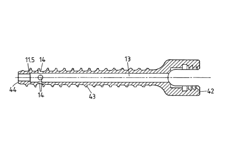
Referring to Figures 3, 4, and 5, a bone screw, namely a further pedicle screw
41 is
depicted. The pedicle screw is, together with a thermoplastic element not
shown in
Figs. 3-5, an embodiment of a pedicle anchor device according to the first
aspect of
the invention. Further, a pedicle screw of the kind depicted in Figures 3-5
may be an
embodiment of an anchoring device body of an anchoring device according to the
third aspect.
The pedicle screw 41 comprises a screw head 42, a threaded section 43, and a
distal
end portion 44. The pedicle screw further comprises a longitudinal through
bore 13
that, towards the distal end, comprises a narrowed portion so that a shoulder
11.5 for
stopping an insert element (not shown in Fig. 5) acting, during the
liquefaction, as
the distal end of the longitudinal bore 13 and inserted from the proximal side
is
formed.
CA 02780285 2016-12-08
- 32 -
The thread has a constant outer diameter (major diameter), whereas a core
diameter
(minor diameter) is larger at the proximal side than at the distal side. More
concretely, in the depicted embodiment, in a central portion of the threaded
section
the core diameter gradually reduces, whereas in peripheral portions the core
diameter
is constant. In other, alternative embodiments, the core diameter is constant,
is
gradually reduced along the entire length of the threaded section, or the core
diameter has a stepped characteristics as taught in WO 90/02526, or has any
other
characteristics. Also, the outer diameter of the threaded section need not be
constant.
Generally, the approach according to the first aspect of the invention may be
combined with any suitable outer thread. Compared to prior art pedicle screws
with a
longitudinal bore, the bore diameter is comparably large to make insertion of
the
liquefiable element ¨ that may be a polymer pin ¨ possible. In the depicted
embodiment, the bore diameter at the more proximal portion of the threaded
section
is 3.1 mm and at the distal portion of the threaded section is 2.9 mm, whereas
the
major diameter is 6.6 mm and the minor diameter is between 4.4 mm and 5.3 mm.
The resulting wall strength has proven to be sufficient.
The screw head is flattened and comprises an inner thread that can be used for
coupling to an apparatus for automated implantation, as described in US patent
application No. 61/259,383.
Referring to Figures 6-12 yet a process of anchoring a pedicle screw of the
kind
illustrated in Figures 3-5 is illustrated. Figure 6 depicts a vertebra 121. As
shown in
Figure 7, in a first step, the access is prepared by pre-drilling a bore 122
at the
appropriate position in a region near the transverse process. The bore 122 may
merely go through the cortical bone, or it may reach through the pedicle into
the
vertebral body and over an entire length of the pedicle screw to be introduced
later,
or a substantial portion thereof. In order to enhance the bone density, the
pre-drilled
hole may be drilled to have an undersize. After the preparation of the bore
122, the
CA 02780285 2012-05-08
WO 2011/054124
PCT/CH2010/000280
- 33 -
pedicle screw 41 is inserted conventionally by screwing. (Fig. 8, Fig. 9). The
orientational stability, due to the limited strength of the cancellous bone in
the
vertebral body, may be limited as illustrated by the double arrow in Fig. 9.
Thereafter, the liquefiable element 21 being a pin of a thermoplastic polymer
is
inserted. If the screw is of the type having a separate insert element for the
directing
structure, prior to or together with the liquefiable element 21 also the
insert element
18 is inserted. Then, as shown in Figure 10, the sonotrode 35 acts to press
the
liquefiable element against the stop face while coupling mechanical vibrations
into
the liquefiable element. The resulting liquefaction, followed by a re-
solidification is
illustrated in Fig. 11. Figure 11 illustrates the situation during the
anchoring process.
Liquefied and re-solidifying material portions 22 pressed into the surrounding
bone
tissue of the vertebra and interpenetrating structures of the latter
strengthen the
cancellous bone tissue. In addition, together with portions of the liquefiable
material
that remain, after re-solidifying, in the device body, the connection provides
a solid
anchoring. Figure 12 illustrates, in partial section, the two pedicle screws
41 inserted
by this method.
The pedicle anchor device 101 shown in Figures 13 and 14 is a further example
of a
device according to the first aspect of the invention. In particular, it is an
embodiment of a device according to the second group of embodiments. The head
portion 102 is similar to the head portion of the pedicle screw described
referring to
Figures 3- 5. Its inner thread may not only be used for coupling to an
apparatus for
automated implantation but also for the fixation of a spine stabilizing rod.
Instead of the depicted head portion, other head geometries of existing or new
spine
stabilizing configurations may be used.
CA 02780285 2012-05-08
WO 2011/054124
PCT/CH2010/000280
- 34 -
The shaft portion 103 does not have a circular cross section (such as for
example a
shape that corresponds essentially to a circular cylinder or to a cone) and
does
therefore not have an outer thread. Rather, the shaft portion is flat and is
helically
twisted. In the depicted configuration, the total angular twist amounts to
about 90 ,
so that a distal end portion of the shaft is approximately perpendicular to a
proximal
portion intended to be located in the pedicle after implantation. By this, the
pedicle
anchor device may have a 'vertical' orientation at the proximal end, an
inclined
orientation following the direction of longest extension of the pedicle cross
section
within the pedicle and a 'horizontal' orientation within the vertebral body.
The pedicle anchor device comprises a longitudinal bore 13 for a thermoplastic
element (not shown) to be inserted. Two radial holes 14 reach from the
longitudinal
bore to an outside. They are arranged near to the distal end of the shaft
portion at the
two flat sides. Like in the previously described embodiments, a thermoplastic
element is inserted in the longitudinal bore and then for anchoring mechanical
energy
is coupled into the thermoplastic element to liquefy portions thereof and to
press the
liquefied portions out of the radial holes into structures of the surrounding
tissue.
In the depicted embodiment, the pedicle anchor device ¨ like other embodiments
¨
has an additional distal (axial) hole 19 that may for example serve as guiding
hole
together with a Kirschner wire and/or may serve for pressing out further
portions of
liquefied material into tissue at the distal end of the device. Such an
additional distal
(axial) hole may especially be advantageous in embodiments, in which like in
the
embodiment of Figures 13 and 14 the distal end portion of the longitudinal
bore
against which the liquefiable material is pressed during liquefaction is not
formed by
a separate insert but by the device body itself.
CA 02780285 2012-05-08
WO 2011/054124
PCT/CH2010/000280
- 35 -
A device of the kind shown in figures 13 and 14 may further optionally
comprise a
directing structure that is structured angularly with respect to a
longitudinal axis of
the longitudinal bore to direct different portions of liquefiable material
from a
liquefiable element to different ones of the holes 14, as described
hereinafter.
The effects of the flat, not circular cross section and of the twist are
schematically
illustrated referring to Figure 24. In Figure 24, the extension of bone tissue
within
the pedicle in which an pedicle anchor device may be anchored is schematically
shown by the ellipse 134. The axes 131, 132 are parallel to the sagittal plane
and the
transversal plane, respectively. Prior art pedicle anchor devices are
restricted to a
circular cross section. The maximal possible cross section thus corresponds to
the
dashed line 135 in Fig. 24. This sets an upper limit of the effective
anchoring cross
section dpnor art- A pedicle anchor device according to aspects of the
invention does
not need to be circular, due to the new anchoring technique with liquefiable
material
pressed out of the longitudinal bore. Thus, the entire available cross section
of the
pedicle may be used if an anchoring device with a for example elliptical cross
section
is used, leading to an enhanced effective anchoring cross section d]. By a
twist as for
example in the embodiments of Figures 13 and 14, the orientation of the more
distal
implant sections may be different from the orientation within the pedicle,
leading to
an even more enhanced effective anchoring cross section d2. This brings an
improved
anchoring strength.
If the quality of the bone tissue of the patient does not require such an
enhanced
effective anchoring cross section, then a pedicle anchor device with a reduced
cross
section may be used, so that the overall cross sectional area is smaller than
the cross
sectional area of prior art pedicle screws (as illustrated by the dashed
line), so that
the implantation causes less impact on the tissue.
CA 02780285 2012-05-08
WO 2011/054124
PCT/CH2010/000280
- 36 -
A further embodiment of a pedicle anchor device and of an according method is
very
schematically illustrated in Figure 25. Fig. 25 shows a cross section through
a
portion of a vertebra along the vertical plane parallel to the pedicle
anchoring device
insertion axis. In contrast to the prior art pedicle screws and to the
embodiments
described hereinbefore, the pedicle anchoring device's 151 length is adapted
to the
size of the patient's vertebra so that the anchoring device ends where the
pedicle
adjoins the vertebral body. This has the following advantages:
- compared to prior art pedicle screws, (the approximate extension of which
is
sketched by the dotted line in Fig. 25), less bone tissue is affected by the
insertion of the device
- the material 152 flown out through the holes is at a position where the
bone
quality is often better. Also, the cortical bone 153 may cause an additional
stability in that the material 152 may find direct mechanical support by the
cortical bone 153. Also a kind of rivet effect may be achieved in that the
material occupies a region around the implant that is larger in cross section
than the region encompassed by the cortical bone immediately proximally of
the material 152.
The latter effect may also be used in case the pedicle anchor device extends
further
into the vertebral body but the position of the holes to which the material
flows out
corresponds to the one of the device of Figure 25.
Whereas in the illustrated embodiments, the head portion and the shaft portion
are
illustrated to be one-piece, this is not necessary. Rather, they may be
separate pieces
somehow attached to each other. Especially, the connection between the shaft
portion
CA 02780285 2012-05-08
WO 2011/054124
PCT/CH2010/000280
- 37 -
and the head may be so that the orientation of the head portion relative to
the shaft
portion may be adjustable. The head portion may be rotatable about an axis, or
the
adjustability may be multi-axial.
The hereinbefore described embodiments may, in addition or as an alternative
to the
mentioned optional features, be provided in the following variants:
- Multi-tiered anchoring or augmentation with a plurality of insert
elements
sequentially inserted, the second, more proximal insert element inserted after
anchoring or augmentation with the first, more distal insert element, or with
a
distal directing structure of the sheath element and with at least one insert
element to be placed proximally of the distal directing structure after
anchoring with the latter. In this, the sheath element comprises one or more
holes for each of the different insert elements or for the distal directing
structure and the at least one insert element. The sheath element may
comprise a plurality if inner shoulders so have a stepwise reduced cross
section towards the distal side, or may comprise different guiding grooves
reaching to different distal positions for the different insert elements.
- The number of holes 14 attributed to a particular directing
structure does not
need to be four as in the illustrated embodiments but may be two (like in
Figs. 13 and 14), three, five, six, etc. Also, the angular (azimuthal) spacing
does not need to be equal between all holes but may be adapted to a particular
situation. For example, for introduction of an implant in a gap of a joint,
the
sheath element may comprise two pairs of neighboring, relatively close holes
at opposite sides. In the case of multi-tiered anchoring, each tear may have
an
individual number and distribution of holes.
CA 02780285 2012-05-08
WO 2011/054124
PCT/CH2010/000280
- 38 -
- The holes may have different shapes and/or different sizes.
The multi-tiered anchoring or augmentation as described herein with a first
liquefaction process taking place with a first directing structure ¨ of the
sheath
element or of an initially separate insert element ¨ the subsequent (after an
at least
partial re-solidification of the liquefied material) addition of a further
directing
structure of a (second) insert element and then a second liquefaction may be
applied
independent of the aspects of the invention.
In Figures 15-19 yet further embodiments of the anchoring device or details
thereof
are illustrated. These further embodiments/details comprise a directing
structure that
is structured angularly with respect to a longitudinal axis of the
longitudinal bore to
direct different portions of the liquefiable material to different ones of the
holes.
Figures 15-17 show a first such embodiment. The directing structure comprises
a
ramp portion 12 sloping away from a center around the longitudinal axis. The
ramp
portion 12 is conical, thus its section with a plane going through the
longitudinal axis
is a straight line. In alternative embodiments, it could be spherical and
concave. At
the radially outer side of the ramp portion, the wall portion of the sheath
element has
four holes 14 equally distributed around the circumference of the sheath
element. At
angular positions between the holes, the directing structure further comprises
walls
15 angularly sub-dividing a portion of the longitudinal bore volume
communicating
with the holes 14. In the depicted embodiment, the walls have a constant
thickness
and comprise a proximal edge 15.1 that in the depicted embodiment slope
towards
the center
CA 02780285 2012-05-08
WO 2011/054124
PCT/CH2010/000280
- 39 -
The angular structuring of the directing structure with the walls between the
holes
firstly has the function to separate portions of the liquefiable element
during
liquefaction. Due to this, approximately equal amounts of liquefied material
is
pressed out of every one of the four holes 14, even if the liquefied material
while
being pressed out of the different holes 14 encounters different resistance. A
second
function of the walls 15 that protrude distally from the directing structure
body and
the stop face is that of energy directors. The liquefiable material will have
a tendency
to start liquefying, under the impact of mechanical vibrations, at edges or
other
pronounced structures either of the sheath element or of the liquefiable
element itself
The energy directing function of the walls 15 is a means for causing the
liquefaction
to start and take place in vicinity of the holes 14 and not, for example, at
the
proximal interface to the sonotrode where too early an onset of liquefaction
would be
undesired.
Figures 18 and 19 show a detail of a pedicle anchor device, for example as
illustrated in Figures 3-5. Compared to the embodiment of Figures 15-17, the
embodiment of Figures 18 and 19 incorporates the following features:
- The outer side of the sheath element comprises an outer thread 11.4.
- The longitudinal bore 13 is a through bore, making the device suitable
for
being guided by a wire in minimally invasive surgery. The through bore is
narrowed towards the distal side so that a shoulder 11.5 is built. The
shoulder
serves as a stop structure for an insert element 18 that terminates the
longitudinal opening for the liquefiable element towards the distal side and
that comprises the directing structure including the walls 15 and the ramp
portions 12. The insert element comprises a distal tapered portion 19 that
together with the shoulder 11.5 co-operates to form a force fit.
CA 02780285 2012-05-08
WO 2011/054124
PCT/CH2010/000280
-40 -
- The
walls 15 protrude proximally further than the holes 14. By this, the effect
of a controlled distribution of liquefied material between the different holes
is
effective even if the resistance encountered for liquefied material pressed
out
of the holes differs strongly between the holes because the interface between
liquefied material and still solid material may be expected to be proximal of
the upper (most proximal) end of the holes 14.
Other stop structures would be possible. For example the sheath element may
comprise at least one interior axial groove that reaches from the proximal end
of the
sheath element to a distal stop and in which a corresponding number of ridges
or
tongues of the insert element is guided. Such an embodiment features the
additional
advantage that the angular relative orientation of the sheath element and the
insert
element is well-defined during insertion. As an even further variant of a stop
structure, the insert element may comprise a spring deflected, during
insertion in the
sheath element, radially inward against a spring force and forcing a stop
flange
portion into an annular stop groove of the sheath element at the appropriate
axial
position. Various other stop structures are possible.
In different embodiments, an insert element 18 may comprise an isotropic stop
face
instead of an angularly structured stop face.
In further variants, a different number of holes may be present, for example
one, two,
three, five, ... holes. The directing structure, if any, is shaped
accordingly. The holes
may have any appropriate shape, such as circular, elongate, ...
All of these features may be present alone, in combination or in any sub-
combination.
CA 02780285 2012-05-08
WO 2011/054124
PCT/CH2010/000280
- 41 -
Referring to Figures 20-23, a method for augmenting hard tissue and/or hard
tissue
replacement material and for implanting a bone screw is described.
The augmentation device comprises a profile body 81 as illustrated in Figure
20. The
profile body is a sheath element with a longitudinal bore 13 and a plurality
of holes
14. The profile body further comprises a portion (that may correspond to the
entire
body or a part thereof) in which the outer profile essentially corresponds to
the
profile of an implant to be implanted in a later step. Especially, the profile
is the
profile of a shaft of a bone screw. To this end, the profile body 81 comprises
an outer
thread 82. The dimensions of the profile body ¨ the drawing illustrates the
profile
body minor diameter d, ¨ correspond to the dimensions of the implant or are
slightly
less than the dimensions of the implant. Fig. 20 shows the minor diameter ds
of the
thread of the screw. Features relating to relative quantities like the thread
pitch are
identical between the profile body and the implant.
The augmentation device may be a device comprising an angularly structured
directing structure to direct different portions of the liqufiable material to
different
ones of the holes 14. Alternatively, the profile body may be a sheath element
in
which a directing structure, against which the liquefiable material is
pressed, is not
angularly structured.
The profile body's outer thread may be a self-tapping thread. Alternatively, a
thread
may be added by a different means, such as a separate tapper.
In a first step, illustrated by Figure 21, the profile body 81 is inserted in
a pre-drilled
bore in the hard tissue and/or hard tissue replacement material or in an other
opening
or gap in the hard tissue and/or hard tissue replacement material, such as a
joint
CA 02780285 2012-05-08
WO 2011/054124
PCT/CH2010/000280
-42 -
space. A liquefiable element that is at least partly liquefiable by the impact
of energy
is placed, before or after insertion of the profile body, in the longitudinal
bore 13. A
sonotrode 35 presses the liquefiable element against a directing structure 83
of the
sheath element while mechanical vibrations are coupled into the liquefiable
element
by the sonotrode. This causes material to liquefy and to be pressed through
the holes
14 into structures of the hard tissue and/or hard tissue replacement material
31.
After all liquefiable material or a sufficient quantity thereof is liquefied,
the
mechanical vibrations are stopped, and the sonotrode is retracted. The profile
body
81 having the outer thread is removed by a twisting movement. In a variant, it
is
possible to remove the profile body and the sonotrode together by the twisting
movement.
Whereas Figure 21 illustrates the profile body with a longidudinal bore that
is
distally closed off by the directing structure 83. In alternative
configurations, it is
also possible to provide an additional, distal, approximately axial hole. By
appropriately choosing the length and diameter of the hole, the amount of
liquefied
material pressed out through such axial hole (if any) compared to the amount
of
liquefied material pressed out throught the other, radial holes may be
engineered. As
a general rule, the higher the ratio between the diameter and the depth of the
hole, the
larger the amount of material exiting. If the ratio is kept below a certain
limit, no
material will exit through the axial hole, but the material will 'freeze' in
the hole.
Figure 22 illustrates the hard tissue and/or hard tissue replacement material
in section
after the augmentation process. The opening 85 in the hard tissue and/or hard
tissue
replacement material comprises the thread, and the wall of the opening is at
least in
regions fortified by the liquefied and re-solidified material 22 that serves
as
augmentation material. Especially when the hard tissue and/or hard tissue
CA 02780285 2012-05-08
WO 2011/054124
PCT/CH2010/000280
-43 -
replacement material has a low density and/or tends to be brittle, this
fortification
brings about a major improvement in the strength of the anchoring of the bone
screw
88 (Fig. 20) inserted thereafter.
The bone screw may be a bone screw based on anchoring according to the state
of
the art, namely based on anchoring by the thread and by friction forces. The
augmentation process brings about an improved anchoring of such a bone screw
both, in terms of resistance against pulling forces and in stability of the
orientation.
Alternatively, the bone screw may itself comprise a longitudinal bore and
holes in
the wall for pressing out liquefiable material. Such liquefiable material may
be
pressed out at positions where the hard tissue and/or hard tissue replacement
material
is fortified by liquefiable material, so that a welding process between the
augmentation material and the newly introduced liquefiable material may take
place.
In addition or as an alternative, the liquefiable material may be pressed out
at
positions where the hard tissue and/or hard tissue replacement material is not
fortified the augmentation material, so that an additional anchoring may
result.
This process is independent of the common shape of the implant and the profile
body. Especially, any kind of thread may be used, and the diameter may be
constant
or not. Also, shapes with features different from a thread may be used, such
as
cylindrical or not-cylindrical shape with longitudinal ridges and/or
indentations,
implants with shapes adapted to the body part in which they are implanted (for
example joint implants), etc. In all embodiments of this aspect, the profile
body may
be used as a trial implant.