Note: Descriptions are shown in the official language in which they were submitted.
CA 02780305 2012-05-08
WO 2011/059652
PCT/US2010/053498
SYSTEMS AND METHODS FOR VERTEBRAL OR OTHER BONE STRUCTURE
HEIGHT RESTORATION AND STABILIZATION
Background
[01] The present disclosure relates to systems and methods for stabilizing
bone structures.
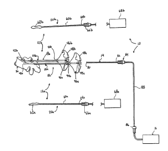
More particularly, it relates to systems and methods for stabilizing, and
restoring the height
of, a bone structure, such as a vertebral body.
[02] Surgical intervention of damaged or compromised bone sites has proven
highly
beneficial for patients, for example patients with back pain associated with
vertebral damage.
[03] Bones of the human skeletal system include mineralized tissue that can
be generally
categorized into two morphological groups: "cortical" bone and "cancellous"
bone. Outer
walls of all bones are composed of cortical bone, which is a dense, compact
bone structure
characterized by a microscopic porosity. Cancellous or "trabecular" bone forms
the interior
structure of bones. Cancellous bone is composed of a lattice of interconnected
slender rods
and plates known by the term "trabeculae".
[04] During certain bone-related procedures, cancellous bone is
supplemented by an
injection of a palliative (or curative) material employed to stabilize the
trabeculae. For
example, superior and inferior vertebrae in the spine can be beneficially
stabilized by the
injection of an appropriate, curable material (e.g., PMMA or other bone cement
or bone
curable material). In other procedures, percutaneous injection of
stabilization material into
vertebral compression factors, by, for example, transpedicular or
parapedicular approaches,
has proven beneficial in relieving pain and stabilizing damaged bone sites.
Such techniques
are commonly referred to as vertebroplasty.
[05] A conventional vertebroplasty technique for delivering the bone
stabilizing material
entails placing a cannula with an internal stylet into the targeted delivery
site. The cannula
and stylet are used in conjunction to pierce the cutaneous layers of a patient
above the hard
tissue to be supplemented, then to penetrate the hard cortical bone of the
vertebra, and fmally
to traverse into the softer, cancellous bone underlying the cortical bone.
Once positioned in
- 1 -
CA 02780305 2012-05-08
WO 2011/059652
PCT/US2010/053498
the cancellous bone, the stylet is removed, leaving the cannula in the
appropriate position for
delivery of curable material that in turn reinforces and solidifies the target
site.
[06] In some instances, an effectiveness of the procedure can be enhanced
by forming a
cavity or void within the cancellous bone, and then depositing the curable
material in the
cavity. For example, a balloon or other expandable device can be initially
deployed and then
expanded. This action, in turn, compresses cancellous bone to faint a cavity,
and may also
cause a "height" of the bone to increase. As a point of reference,
vertebroplasty is a common
treatment for a fractured vertebral body, and the height of a fractured
vertebral body is
oftentimes significantly less than a native or natural height. It has been
postulated that the
height of a fractured vertebral body can be restored or elevated to a near-
normal state when
subjected to internal expansion via a balloon or other expandable member. The
mechanics of
height restoration in conjunction with vertebroplasty stabilization is
currently unclear at best.
For example, conventional techniques employ a bipedicular approach in which
two balloons
are inserted into the vertebral body and inflated, resulting in an increase in
height (and the
cavity or cavities described above). The sequence of subsequent deflation and
delivery of
curable material is not well documented.
[07] In light of the above, there exists a need in the medical device field
for improved
systems and methods for restoring the height of, and stabilizing, a fractured
vertebral body or
other bone structure.
Summary
[08] Some aspects in accordance with principles of the present disclosure
relate to a
method for stabilizing a bone structure of a patient, and includes directing a
first expandable
member in a contracted state to a first location within the bone structure. A
second
expandable member is directed to a second location within the bone structure
in a contracted
state, with the second location being spaced from the first location. The
first and second
expandable members are transitioned to an expanded state, thereby forming
first and second
cavities within the bone structure. The first expandable member is then
transitioned from the
expanded state back to the contracted state while maintaining the second
expandable member
in the expanded state. The first expandable member is removed from the bone
structure, and
- 2 -
CA 02780305 2015-10-14
a curable material delivered into the first cavity. The second expandable
structure is
subsequently transitioned to the contracted state and removed from the bone
structure. A
curable material is then delivered into the second cavity. With this
technique, the height of
the bone structure is restored via expansion of the two expandable members,
and is retained
throughout the procedure first by the second expandable member during delivery
of curable
material into the first cavity, and then by the hardened material in the first
cavity during
removal of the second expandable member and delivery of curable material into
the second
cavity. In some constructions, at least the second expandable member is
exteriorly coated
with an anti-sticking material (e.g., silicone, polypropylene, etc.)
configured to resist bonding
with the selected curable material (i.e., the curable material in the first
cavity).
108a1 In accordance with an aspect of an embodiment, there is provided a
method for
stabilizing a bone structure of a patient, the method comprising: directing a
first expandable
member in a contracted state to a first location within the bone structure;
directing a second
expandable member in a contracted state to a second location within the bone
structure, the
second location being spaced from the first location; transitioning the first
expandable
member to an expanded state that forms a first cavity within the bone
structure; transitioning
the second expandable member to an expanded state that forms a second cavity
within the
bone structure; transitioning the first expandable member from the expanded
state to the
contracted state while maintaining the second expandable member in the
expanded state;
removing the first expandable member from the bone structure; delivering a
curable material
into the first cavity while the second expandable member remains in the
expanded state
within the bone structure at the second location; transitioning the second
expandable member
from the expanded state to the contracted state; removing the second
expandable member
from the bone structure; and delivering a curable material into the second
cavity.
108b1 In accordance with another aspect of an embodiment, there is
provided a method for
stabilizing a vertebral body of a patient, the method comprising: directing a
first expandable
member in a contracted state to a first location within the vertebral body;
directing a second
expandable member in a contracted state to a second location within the
vertebral body, the
second location being spaced from the first location; transitioning the first
expandable
member to an expanded state that forms a first cavity within the vertebral
body; transitioning
the second expandable member to an expanded state that forms a second cavity
within the
- 3 -
CA 02780305 2015-10-14
vertebral body; transitioning the first expandable member from the expanded
state to the
contracted state while maintaining the second expandable member in the
expanded state;
removing the first expandable member from the vertebral body; delivering a
curable material
into the first cavity; transitioning the second expandable member from the
expanded state to
the contracted state; removing the second expandable member from the vertebral
body; and
delivering a curable material into the second cavity
108c1 In accordance with another aspect of an embodiment, there is
provided a method for
stabilizing a fractured bone structure of a patient, the fractured bone
structure having a
fractured height, the method comprising: expanding the bone structure to a
restored height
greater than the fractured height by transitioning at least a first expandable
member inserted
into the bone structure from a contracted state to an expanded state;
delivering a curable
material into a first cavity formed in the bone structure while the first
expandable member
maintains the bone structure at the restored height; allowing the curable
material to harden
while the first expandable member maintains the bone structure at the restored
height; and
after the curable material has hardened, removing the first expandable member
from the bone
structure.
[08d] In accordance with another aspect of an embodiment, there is
provided a system for
stabilizing a bone structure of a patient, the system comprising: a first
delivery assembly for
directing a first expandable member in a contracted state to a first location
within the bone
structure; a second delivery assembly for directing a second expandable member
in a
contracted state to a second location within the bone structure, the second
location being
spaced from the first location; wherein the first delivery assembly includes a
first cavity-
forming device for transitioning the first expandable member to an expanded
state that forms
a first cavity within the bone structure; the second delivery assembly
includes a second
cavity-forming device for transitioning the second expandable member to an
expanded state
that forms a second cavity within the bone structure; wherein the first cavity-
forming device
is configured to transition the first expandable member from the expanded
state to the
contracted state with the second cavity-forming device maintaining the second
expandable
member in the expanded state, and to remove the first expandable member from
the bone
structure; a first curable material is configured to be delivered into the
first cavity while the
second expandable member remains in the expanded state within the bone
structure at the
- 3a -
CA 02780305 2015-10-14
=
second location; the second cavity-forming device is configured to transition
the second
expandable member from the expanded state to the contracted state and to
remove the second
expandable member from the bone structure; and a second curable material is
configured to
be delivered into the second cavity.
[08e] In accordance with another aspect of an embodiment, there is
provided a system for
stabilizing a vertebral body of a patient, the system comprising: a first
delivery assembly for
directing a first expandable member in a contracted state to a first location
within the
vertebral body; a second delivery assembly for directing a second expandable
member in a
contracted state to a second location within the vertebral body, the second
location being
spaced from the first location; wherein the first delivery assembly includes a
first cavity-
forming device for transitioning the first expandable member to an expanded
state that forms
a first cavity within the vertebral body; the second delivery assembly
includes a second
cavity-forming device for transitioning the second expandable member to an
expanded state
that forms a second cavity within the vertebral body; wherein the first cavity-
forming device
is configured to transition the first expandable member from the expanded
state to the
contracted state with the second cavity-forming device maintaining the second
expandable
member in the expanded state and to remove the first expandable member from
the vertebral
body; a first curable material is configured to be delivered into the first
cavity; the second
cavity-forming device is configured to transition the second expandable member
from the
expanded state to the contracted state and to remove the second expandable
member from the
vertebral body; and a second curable material is configured to be delivered
into the second
cavity.
108f] In accordance with a further aspect of an embodiment, there is
provided a system for
stabilizing a structure, the system comprising: a first expandable member
capable of
transition between a contracted state and an expanded state, the first
expandable member
deliverable to a first location within the structure to form a cavity within
the bone structure; a
second expandable member capable of transition between a contracted state and
an expanded
state, the second expandable member deliverable to a second location within
the structure, the
second location being spaced from the first location, to form a second cavity
within the
structure; a curable material for delivery into the first cavity, while the
first expandable
member is in the contracted state and removed from the structure and further
while the
- 3b -
CA 02780305 2015-10-14
,
second expandable member is maintained in the expanded state; a curable
material for
delivery into the second cavity, while the second member is in the contracted
state and
removed from the structure.
Brief Description of the Drawings
[09] FIG. 1 is an exploded view of a curable material delivery and height
restoration
system in accordance with principles of the present disclosure;
[10] FIGS. 2 A and 2B illustrate initial use of the system of FIG. 1 in
performing a height
restoration and curable material delivery procedure relative to a vertebra,
with the vertebra
being shown from a superior perspective;
[11] FIG. 2C is a lateral view of the vertebral body of FIGS. 2A and 2B;
and
[12] FIGS. 3A-6 illustrate the system of FIG. 1 in further performing the
height restoration
and curable material delivery procedures of the present disclosure.
Detailed Description
[13] One embodiment of a curable material delivery and height restoration
system 10 in
accordance with principles of the present disclosure is shown in FIG. 1. The
system 10
includes a first delivery assembly 12a, a second delivery assembly 12b, and at
least one
source of curable material 16. The delivery assemblies 12a, 12b can be
substantially identical,
and each includes a cannula device 18a, 18b and a cavity-forming device 20a,
20b. Details
on the various components are provided below. In general terms, however, the
cannula
devices 18 a, 18b each include a cannula 22a, 22b for insertion into a bone
site of
- 3c -
CA 02780305 2012-05-08
WO 2011/059652
PCT/US2010/053498
interest in a patient. In the embodiment depicted in FIG. 1, the bone site of
interest is a
vertebra 30. Once the cannulas 22a, 22b are desirably located relative to the
vertebra 30, a
portion of each of the cavity-forming devices 20a, 20b are delivered to the
vertebra 30 via the
corresponding cannula 22a, 22b, and operated to form cavities. The second
cavity-forming
device 20b (alternatively the first cavity-forming device 20a) is removed, and
the source of
curable material 16 connected to the second cannula 22b. In this regard, an
optional delivery
tube 14 can be employed, extending from the source 16 and through the second
cannula 22b.
Regardless, the curable material source 16 is then operated to deliver curable
material to the
cavity via the second cannula 22b and/or the delivery tube 14. Subsequently,
the first cavity-
forming device 20a is removed and the curable material source 16 is connected
to the first
cannula 22a (for example, via the optional delivery tube 14). The curable
material source 16
is operated to deliver curable material into the corresponding cavity. With
this approach, the
systems and methods of the present disclosure can consistently restore a
height of the
vertebra (or other bone site) 30 to a normal or near-nolinal state, and the
delivered curable
material provides desired stabilization.
[14] The system 10 can be used for a number of different procedures
including, for
example, vertebroplasty and other bone augmentation procedures in which
curable material is
delivered to a site within bone, as well as possibly to remove or aspirate
material from a site
within bone. The system 10 is highly useful for delivering a curable material
in the form of a
bone curable material. The phrase "curable material" within the context of the
substance that
can be delivered by the system 10 of the present disclosure described herein
is intended to
refer to materials (e.g., composites, polymers, and the like) that have a
fluid or flowable state
or phase and a hardened, solid or cured state or phase. Curable materials
include, but are not
limited to, injectable bone cements (such as polymethylmethacrylate (PMMA)
bone curable
material), which have a flowable state wherein they can be delivered (e.g.,
injected) by a
cannula to a site and subsequently cure into hardened, cured material. Other
materials such
as calcium phosphates, bone in-growth materials, antibiotics, proteins, etc.,
can be used in
placed of, or to augment bone cement (but do not affect an overriding
characteristic of the
resultant formulation having a flowable state and a hardened, solid, or cured
state). This
would allow the body to reabsorb the curable material and/or improve the
clinical outcome
based on the type of filler implant material. While FIG. 1 illustrates a
single source of
- 4 -
CA 02780305 2017-02-22
,
curable material 16, in other embodiments, two (or more) sources can be
provided. The
sources can contain identical curable material compositions; alternatively,
the compositions
can differ (e.g., a first source can contain bone cement, while a second
source contains a
mixture of bone cement and bone in-growth material).
[15] As mentioned above, the cannula devices 18a, 18b can be
substantially identical, and
each includes the cannula 22a, 22b. The cannula 22a, 22b is provided to be
positioned in (or
immediately proximate) the target or injection site for delivery of the
corresponding cavity-
forming device 20a, 20b, as well as curable material. The cannula 22a, 22b is
preferably made
of a surgical grade of stainless steel, but may be made of known equivalent
material(s) that
are both biocompatible and substantially non-compliant at the expected
operating pressures.
The cannulas 22a, 22b each define a proximal region 40a, 40b, a distal end
42a, 42b, and ,a
lumen 44a, 44b (referenced generally), respectively, to allow various
equipment such as the
cavity-forming device 20a, 20b, the optional delivery tube 14, one or more
stylets (not
shown), etc., to pass therethrough.
1161 Surrounding the proximal region 40a, 40b of the cannula 22a,
22b is an optional
handle 46a, 46b for manipulating the cannula 22a, 22b and connecting the
cannula 22a, 22b
with one or more of the cavity-forming device 20a, 20b and/or the optional
delivery tube 14.
In some constructions, the cannula device 18a, 18b can further include a
handle connector
48a, 48b serving as a proximal end of the corresponding cannula 22a, 22b. The
handle
connector 48a, 48b can simply be an extension of the cannula 22a, 22b.
Alternatively, the
handle connector 48a, 48b can incorporate features forming part of a locking
mechanism
component of the system 10. For example, the handle connector 48a, 48b can
optionally
include a luer-lock type of connector, but other known connecting mechanism
may be
successfully interchanged (e.g., a conventional threaded hole, a threaded
locking nut
arrangement, etc.). Features of the optional locking mechanism are described
in U.S.
Publication No. 2007/0198024.
[17] The cavity-forming devices 20a, 20b are substantially
identical and can assume
various forms appropriate for forming a void or cavity within bone. In this
regard, each of the
cavity-forming devices 20a, 20b includes an elongated body 60a, 60b distally
connected
- 5 -
CA 02780305 2012-05-08
WO 2011/059652
PCT/US2010/053498
to or forming a working end 62a, 62b. The elongated body 60a, 60b is sized to
be slidably
inserted within the lumen 44a, 44b of the corresponding cannula 22a, 22b, and
can include
one or more tubes, shafts, etc., necessary for operation of the corresponding
working end 62a,
62b. Regardless, a proximal region 64a, 64b of the elongated body 60a, 60b is
optionally
connected to or forms a cannula connector 66a, 66b. The cannula connector 66a,
66b can
assume various forms conducive for selective, rigid attachment to the
corresponding handle
connector 48a, 48b as described above (e.g., the cannula connector 66a, 66b
and the
corresponding handle connector 48a, 48b collectively form a locking
mechanism), and thus
can include or contain a luer-lock threaded fitting. Alternatively, the
cannula connector 66a,
66b can be omitted, and depth markings (not shown) included along an exterior
of the
proximal region 64a, 64b that facilitate desired locating of the working end
62a, 62b relative
to the corresponding cannula 22a, 22b as described below.
[18] The working end 62a, 62b can include one or more components
appropriate for
forming a cavity or void within bone. For example, in some constructions, the
working end
62a, 62b includes one or more expandable or inflatable members (e.g., a single
balloon,
multiple balloons, a single balloon with two or more discernable inflation
zones, etc.)
constructed to transition between a contracted (e.g., deflated) state in which
the working
end/balloon 62a, 62b can be passed through the corresponding lumen 44a, 44b,
and an
expanded (e.g., inflated) state in which the working end/balloon 62a, 62b
expands and
compacts contacted cancellous bone. In this regard, a size and shape of the
working
end/balloon 62a, 62b can be predetermined and/or restrained with one or more
additional
components (not shown), such as internal and/or external restraints.
Regardless, the working
end/balloon 62a, 62b is structurally robust, able to withstand (e.g., not
burst) at expected
inflation pressures and when in contact with bone. Further, the first working
end 62a and the
second working end 62b can be identical or different.
[19] For reasons made clear below, at least one, and in some embodiments
both, of the
working ends/balloons 62a, 62b are optionally exteriorly coated with a
material adapted or
tailored to resist bonding with the curable material being delivered to the
vertebra 30. The
anti-sticking coating can assume various forms as a function of the selected
curable material,
and in some embodiments is a silicone coating. Other materials exhibiting
adversion to
bonding with bone cement are also envisioned, for example, polypropylene. In
related
- 6 -
CA 02780305 2012-05-08
WO 2011/059652
PCT/US2010/053498
embodiments, a thin-walled expandable sleeve constructed of the selected anti-
sticking
material (e.g., a polypropylene sleeve) can be disposed over the working
end/balloon 62a,
62b. Though not shown, one or both of the cavity-forming devices 20a, 20b can
include a
valve or similar component that operates to selectively seal the working
end/balloon 62a,
62b.
[20] The cavity-forming devices 20a, 20b each further include one or more
additional
components connected or operable through the proximal region 64a, 64b for
actuating the
corresponding working end 62a, 62b. By way of one non-limiting example, then,
each of the
cavity-forming devices 20a, 20b can include a source 68a, 68b of pressurized
fluid (e.g.,
contrast medium) for inflating the balloon(s) carried or formed by the
corresponding working
end 62a, 62b. A hand-held, syringe-type pump can be used as the pressurized
source. In
other embodiments, a single one of the sources of pressurized fluid 68a or 68b
can be
provided and employed to inflate both of the working ends/balloons 62a, 62b
individually.
[21] Where provided, the optional delivery tube 14 is sized for insertion
within the lumens
44a, 44b, and defines a distal tip 80 and a proximal section 82. As described
below, the
delivery tube 14 can be employed to deliver curable material to the target
site. Thus, the
delivery tube 14 has an outer diameter that is smaller than a diameter of the
lumens 44a, 44b;
however, the outer diameter of the delivery tube 14 should not be so small as
to allow curable
material to readily travel around the outside of the delivery tube 14 and back
into the
corresponding cannula 22a, 22b.
[22] A cannula connector 84 is optionally coupled to, or formed by, the
proximal section
82 of the delivery tube 14. The cannula connector 84 is akin to the optional
cannula
connector 66a, 66b described above (e.g., combines with the selected handle
connector 48a,
48b to form a locking mechanism), and thus can assume any of the forms
previously
described. Alternatively, the delivery tube 14, where provided, can form depth
markings (not
shown) along the proximal section 82 that facilitates desired locating of the
distal tip 80
relative to the cannula 22a, 22b during use.
[23] The delivery tube 14 is configured for fluid coupling to the curable
material source
16. In some embodiments, a portion of the delivery tube 14 projects proximally
beyond the
optional cannula connector 84, and is fluidly coupled to the curable material
source 16, for
- 7
CA 02780305 2012-05-08
WO 2011/059652
PCT/US2010/053498
example via an injection connector 86. Alternatively, auxiliary tubing 88 can
be provided
with the curable material source 16, and fluidly connected to the delivery
tube 14 via the
optional cannula connector 84. In yet other embodiments, the delivery tube 14
is omitted,
and the curable material source 16 connected directly to the handle
connector/proximal end
48a, 48b (e.g., the auxiliary tube 88 is connected to the connector 48a, 48b;
or the tubing 88
eliminated and the curable material source 16 (e.g., a syringe) directly
coupled to the
connector 48a, 48b).
[24] The curable material source 16 can assume various foiins appropriate
for delivering
the desired curable material, and may typically comprise a chamber filled with
a volume of
curable material and employing any suitable injection system or pumping
mechanism to
transmit curable material out of the chamber and through the delivery tube 14.
Typically, a
hand injection system is used where a user applies force by hand to an
injector. The force is
then translated into pressure on the curable material to flow out of the
chamber. A motorized
system may also be used to apply force.
[25] While the system 10 has been described as including the single source
of curable
material 16, in other constructions, a separate source of curable material 16
can be provided
for each of the delivery assemblies 12a, 12b. Similarly, two (or more) of the
optional
delivery tubes 14 can be included. Along these same lines, the system 10 can
alternatively be
configured such that the curable material source 16 is directly connected to
one or both of the
cavity-forming devices 20a, 20b (e.g., the elongated body 60a of the first
cavity-forming
device 20a can form or terminate at a nozzle proximate (e.g., distal) the
working end 62a and
through with the curable material can be directly dispensed).
[26] Regardless of an exact configuration, the system 10 in accordance with
principles of
the present disclosure is highly useful in performing a wide variety of height
restoration and
bone stabilization procedures as part of an overall curable material delivery
procedure. To
this end, FIG. 2A illustrates initial use of the system 10 in restoring the
height of, and
delivering curable material into, a target site of a vertebra 100. In general
terms, the vertebra
100 includes pedicles 102a, 102b and a vertebral body 104 definin' g a
vertebral wall 106
surrounding bodily material 108 (e.g., cancellous bone, blood, marrow, and
soft tissue). The
pedicles 102a, 102b extend from the vertebral body 104 and surround a
vertebral foramen
- 8 -
CA 02780305 2012-05-08
WO 2011/059652
PCT/US2010/053498
110. As a point of reference, systems of the present disclosure are suitable
for accessing a
variety of bone sites. Thus, while the vertebra 100 target site is
illustrated, it is to be
understood that other bone sites can be accessed and treated by the system 10
(e.g., femur,
long bones, ribs, sacrum, etc.).
[27] The first and second cannulas 22a, 22b are initially employed to form
first and second
access paths to first and second target site locations 120a, 120b. For
example, the cannulas
22a, 22b are inserted in a bipedicular fashion through respective ones of the
pedicles 102a,
102b and into the bodily material 108. The cannulas 22a, 22b provide access to
the
corresponding target site 120a, 120b at the open distal ends 42a, 42b thereof.
One or more
stylets (not shown) can be employed to assist in forming/accessing the target
sites 120a,
120b. For example, a series of differently-sized or configured (e.g.,
sharpened and blunt)
stylets can be successively delivered through the respective cannula 22a, 22b
to form a
channel to the target site 120a, 120b. Alternatively, or in addition, an outer
guide cannula
(not shown) can initially be deployed to faun an access path for subsequent
insertion of the
cannulas 22a, 22b.
[28] Once the cannulas 22a, 22b are positioned within the bodily material
108 at the
desired target sites 120a, 120b, the cavity-forming devices 20a, 20b are
assembled to the
corresponding cannula 22a, 22b. For example, and as shown in greater detail in
FIG. 2B, the
elongated body 60a, 60b is slidably inserted within the corresponding cannula
22a, 22b, with
the respective working end 62a, 62b being distally advanced therethrough. More
particularly,
with configurations in which the working end 62a, 62b is a balloon or other
expandable
member famiat, the working end/balloon 62a, 62b is transitioned to a
contracted state (e.g.,
deflated) so as to be slidably received through the lumen 44a, 44b. The
elongated body 60a,
60b is positioned relative to the corresponding cannula 22a, 22b such that the
respective
working end/balloon 62a, 62b extends distal the corresponding cannula distal
end 42a, 42b.
For example, where the elongated body 60a, 60b includes depth markings as
described above,
the appropriate depth marking is aligned with the corresponding handle
connector 48a, 48b
(FIG. 1), thereby ensuring that the working end/balloon 62a, 62b is fully
deployed or
extended beyond the corresponding cannula distal end 42a, 42b. In other
constructions, upon
connection of the optional cannula connector 66a, 66b and the corresponding
handle
connector 48a, 48b, the working end/balloon 62a, 62b is distal the
corresponding distal end
- 9 -
CA 02780305 2012-05-08
WO 2011/059652
PCT/US2010/053498
42a, 42b and is positioned at the corresponding target site 120a, 120b.
Regardless, placement
of the cavity-forming devices 20a, 20b can be performed simultaneously or
consecutively.
[29] As a point of reference, FIG. 2C provides a lateral view of the
vertebral body 104 in
which the first working end/balloon 62a has been deployed (and in the
contracted state). As
shown, the vertebral body 104 is fractured (referenced generally at 122) and
thus exhibits a
fractured height HF that is less than a natural or native height HN
(designated generally).
[30] With reference to FIG. 3A, the cavity-forming devices 20a, 20b are
operated to cause
the corresponding working ends/balloons 62a, 62b to form first and second
cavities or voids
124a, 124b, respectively, in the bodily material 108. For example, the working
ends/balloons
62a, 62b can be expanded (e.g., inflated) substantially simultaneously.
Alternatively, with
embodiments in which a single inflation source 68a or 68b (FIG. 1) is
provided, the first
working end/balloon 62a is initially inflated and then sealed in the expanded
or inflated state.
The inflation source 68a or 68b is then fluidly connected to the second
working end/balloon
62b and operated to cause expansion thereof. Following expansion of the
working
ends/balloon 62a, 62b, the expanded working ends 62a, 62b are both supporting
the vertebral
body 108. In this regard, and as best illustrated in FIG. 3B, expansion of the
working
ends/balloons 62a, 62b not only forms the cavities 124a, 124b, but also
restores or enhances a
height of the fractured vertebral body 104. More particularly, a restored
height HR is
established that beneficially approximates the natural height HN. The restored
height HR may
be the same as, slightly less than, or slightly greater than, the natural
height HN (FIG. 2C);
regardless, the restored height HR is greater than the fractured height HF
(FIG. 2C).
[31] Returning to FIG. 3A, the second cavity-forming device 20b is then
operated to
transition the second working end/balloon 62b from the expanded state to the
contracted state
(e.g., the second balloon 62b is deflated). In the contracted state of the
second working
end/balloon 62b, the second cavity-forming device 20b can be removed from the
second
carmula 22b as shown in FIG. 4A. Subsequently, and with reference to FIG. 4B,
the optional
delivery tube 14 is disposed within the second cannula 22b, and the source of
curable
material 16 (FIG. 1) operated to deliver curable material 130 into the second
cavity 124b.
With other constructions, the delivery tube 14 is omitted and the curable
material 130 is
delivered to the second cavity 124b directly through the second carmula 22b.
Once a desired
- 10 -
CA 02780305 2012-05-08
WO 2011/059652
PCT/US2010/053498
volume of the curable material 130 has been delivered to the second cavity
124b, the delivery
tube 14 (where provided) and optionally the second cannula 22b are removed
from the
patient. Throughout this portion of the procedure, the first working
end/balloon 62a remains
expanded and in place, maintaining the vertebral body 104 at the restored
height HR (FIG.
3B). It will be understood that it is equally acceptable to reverse the order
and instead
initially fill the first cavity 124a with the curable material 130 (i.e., the
first cavity-forming
device 20a removed from the vertebral body 104 while the second working
end/balloon 62b
remains in place during subsequent dispensement of the curable material 130
into the first
cavity 124a).
[32] Once the curable material 130 within the second cavity 124b has
sufficiently hardened
or cured, the second cannula 22b can be removed and the first working
end/balloon 62a is
transitioned from the expanded state to the contracted state (e.g., the first
balloon 62a is
deflated) as shown in FIG. 5. In this regard, the hardened, curable material
130 in the second
cavity 124b supports and maintains the vertebral body 104 at the restored
height HR (FIG.
3B) while the first working end/balloon 62a is transitioned (e.g., deflated).
Further, the
optional anti-sticking coating on the first working end/balloon 62a resists
bonding with the
curable material 130 delivered to the second cavity 124b such that the
hardened curable
material 130 in the second cavity 124b will not prevent the first worldng
end/balloon 62a
from deflating should the curable material 130 come into contact with an
exterior of the first
working end/balloon 62a. Regardless, in the contracted state, the first cavity-
forming device
20a can be removed from the patient, and is optionally replaced with the
delivery tube 14.
Finally, as shown in FIG. 6, curable material 132 is delivered into the first
cavity 124a (either
through the optional delivery tube 14 or directly through the first cannula
22a with
embodiments in which the delivery tube 14 is omitted).
[33] Systems and methods in accordance with the present disclosure provide
a marked
improvement over previous designs and techniques. By inflating and dispensing
curable
material in a step-wise fashion, the height of a fractured vertebral body (or
other bone site of
interest) can be restored and retained.
[34] Although the present disclosure has been described with reference to
preferred
embodiments, workers skilled in the art will recognize that changes can be
made in form and
-11-
CA 02780305 2012-05-08
WO 2011/059652 PCT/US2010/053498
detail without departing from the spirit and scope of the present disclosure.
- 12 -