Note: Descriptions are shown in the official language in which they were submitted.
CA 02780327 2012-05-08
WO 2011/059706 PCT/US2010/054247
1
POWER OSCILLATION DAMPING EMPLOYING A
FULL OR PARTIAL CONVERSION WIND TURBINE
FIELD OF THE INVENTION
The present invention relates generally to control of power systems and more
specifically to power oscillation damping employing a full-conversion or
partial
conversion wind turbine or a doubly-fed induction generator wind turbine.
BACKGROUND OF THE INVENTION
In most cases, there is a phase angle difference between a sinusoidal current
supplied to a power grid by an alternating current generator and a voltage at
the
generator's terminals. This phase angle difference between the voltage and the
current
is due to the nature of the load on the power grid. For a purely resistive
load (i.e.,
having no energy storage properties) the voltage and current are in phase,
i.e., the
current and voltage reverse their polarity simultaneously and a direction of
power
remains fixed and does not reverse.
For a purely reactive load the current and voltage are 90 degrees out of phase
and the net power flow is zero as the power flows to and returns from the load
due to
the energy storage features of the reactive load. If the load is purely
inductive, the
current lags the voltage by 90 degrees. A lag angle is between 0 and 90
degrees for a
load that is both inductive and resistive. For a purely capacitive load the
current leads
the voltage by 90 degrees. A lead angle is between 0 degrees and 90 degrees
for a
load with both resistive and capacitive properties. Thus the magnitude of the
phase
angle difference depends on the resistance, inductance and capacitance of the
load to
which the generator supplies power and on the characteristics and operating
point of
the generator.
For a load with both reactive and resistive properties, the current phase
angle
(relative to the voltage phase angle) can be resolved into an in-phase
component (i.e.,
in-phase with the voltage) and an out-of-phase component (i.e., a 90 degrees
out-of-
phase with the voltage). Thus the component of the current that is in phase
with the
voltage results in the delivery of real or active power into the load. The
component of
the current that is phase shifted by 90 degrees from the voltage, referred to
as reactive
power, performs no useful work. The energy associated with this current flows
from the
CA 02780327 2012-05-08
WO 2011/059706 PCT/US2010/054247
2
generator to the load and then back to the generator, resulting in a net zero
energy at
any point in the circuit.
The generation and control of reactive power in an electrical transmission
system
is important to the overall power system efficiency and stability. Capacitors,
capacitive
loads and capacitive compensators are considered to generate reactive power.
Inductors, inductive loads (e.g., transformers and motors) and inductive
compensators
are considered to consume reactive power. Also, lightly loaded transmission
lines
generate reactive power and heavily loaded lines consume reactive power.
Electric power transmission systems are designed recognizing that the three
power system parameters of impedance, voltage and phase angle between the
current
and voltage cannot be controlled fast enough to accommodate dynamic system
conditions. Furthermore, available control devices usually compensate or
control only
one of the three variables. Thus transmission systems having been designed
with fixed
or mechanically-switched series and shunt reactive compensations, together
with
voltage regulating and phase-shifting transformer tap changers, to optimize
line
impedance, minimize voltage variation, and control power flow under steady-
state or
slowly-changing load conditions. The dynamic system problems have been
typically
addressed by over-design, i.e., designing the system with generous stability
margins to
recover from worst case contingencies resulting from faults, line and
generator outages,
and equipment failures. This practice of over design results in the under
utilization of the
transmission system.
In recent years, energy demands, environmental considerations, right-of-way
access, and cost issues have delayed the construction of both generation
facilities and
new transmission lines. This has necessitated a change in the traditional
power system
concepts and practices; better utilization of existing power systems has
become
imperative. But higher utilization of power transmission systems, without an
appreciable degradation in the reliability of the supply of electric power, is
possible only
if the power flow can be controlled rapidly following dynamic system
disturbances.
Electric power is provided by a rotating generator driven by a turbine. The
mechanical output power of the turbine cannot be changed quickly to balance
the
mechanical power with a rapidly changing electrical power demand.
Consequently, the
generators are forced to accelerate or decelerate responsive to changes in
power
CA 02780327 2012-05-08
WO 2011/059706 PCT/US2010/054247
3
demand. For example, an electrical demand greater than the electrical
generation
causes the generator to slow down and the frequency of the electrical energy
on the
distribution system may drop. Conversely, when excess electrical energy is
available
the generator accelerates and the electrical system frequency increases.
This change in the generator's rotational speed results in a corresponding
angular position change (also referred to as a rotor power angle change), with
respect
to a constant angular position maintained elsewhere on the transmission line
by other
generators, i.e., typically a large, distant, undisturbed generator also
referred to as an
"infinite" bus. The angular position change between generators alters the
amount of
electric power transmitted. Once the disturbance is over (e.g., a fault
cleared, new
transmission system configuration, new power generation level or new load
demand
established) the disturbed generators try to reach a new angular position
appropriate to
the new steady-state condition of the power system. However, the generators
together
with the associated turbines have significant rotational inertia and, for this
reason the
new angular position is usually reached only after an "overshoot" or
oscillation period.
These transient angular changes and oscillations, of course, manifest
themselves as
transient electric power changes and oscillations. In the extreme case, these
transient
changes cannot be stabilized; the equilibrium between the available mechanical
power
and transmitted electric power cannot be reestablished and the angular
"overshoot"
increases. The generator then accelerates until it is automatically shut down
when a
maximum rotational speed is reached. The angular oscillation may also continue
or
even increase due to insufficient oscillation damping in the power system.
These
undamped oscillations may ultimately cause the power system to be shut down by
tripping of protective devices.
One measure of the ability of a power system to provide electric power to meet
load demand is power system "stability." "Transient stability" refers to the
capability of
the power system to recover normal operation following a major disturbance
(fault, loss
of generation, etc.). "Dynamic stability" refers to the capability of the
power system to
recover normal operation following a minor disturbance that initiates power
oscillations.
Thus a dynamically stable power system has positive damping to damp or remove
the
power oscillations.
CA 02780327 2012-05-08
WO 2011/059706 PCT/US2010/054247
4
Various devices are in use to stabilize bulk-power transmission and
distribution
systems and to improve the transient and dynamic stability of the power
system. These
devices, referred to generally as flexible AC transmission system (FACTS)
devices can
provide rapid voltage regulation and power flow control. FACTS devices
include: static-
var compensators (SVC), static synchronous compensators (STATCOMS), and
thyristor-controlled series capacitors (TSCSs). Use of these devices to limit
effects of
power system impedance changes permits loading of the transmission facilities
to levels
approaching their ultimate thermal capacity. These devices may regulate system
voltage and/or provide power modulation to damp electromechanical
oscillations. In
any case, the FACTS devices control the voltage, impedance or phase angle on
the
power system.
STATCOM devices lack any substantial real energy storage and are simply
voltage-sourced inverters that regulate voltage of the grid via a step up
transformer. In
present devices, only transient energy storage is provided by a relatively
small DC
capacitor that is used to exchange reactive power between phase conductors of
the
power system. Since the STATCOM can only regulate voltage, the STATCOM is
limited in the degrees of freedom and sustained power damping oscillation
actions that
it can contribute to the grid.
For example, one STATCOM was developed specifically for power oscillation
damping for inter-area power oscillations by modulating the voltage at the
interconnection. It is known that inter-area power oscillations occur on
transmission
systems with long lines and large physical distances between major generation
sources. Typically, after a disturbance, groups of generators in a first
geographic region
swing against another group of generators in a second geographic region
separated
from the first region by a series of long transmission lines. Normally, these
oscillations
are of a very low frequency (typically between 0.1 and 0.7 Hz) and are poorly
damped
in the absence of supplemental damping.
Inter-area power oscillations are a particularly common phenomenon in the US
western states, Canada, and other regions with low power generation density
and long
transmission lines between generating units. To damp these inter-area
oscillations,
synchronous generators in these regions are typically required to have power
system
CA 02780327 2012-05-08
WO 2011/059706 PCT/US2010/054247
stabilizers (PSSs) to provide supplemental damping to ensure the oscillations
are
damped before they cause system instabilities.
Wind turbines exploit wind energy by converting the wind energy to electricity
for
distribution to users. Several factors must be considered in identifying a
wind turbine
site and designing the turbine, including, tower height, control systems,
number of
blades, and blade shape. Wind turbines are typically sited at isolated
locations where
the grid may be regarded as relatively "weak" due to the few generating plants
and long
distances between plants. A "weak" system may be characterized by a relatively
low
short circuit strength, e.g., less than about 10kA, and/or a variations in
voltage at
different points on the system.
The rotor of a fixed-speed wind turbine is turned by the wind-driven blades
and
operates through a gear box (i.e., a transmission) at a fixed rotational
speed. The fixed-
speed wind turbine is typically connected to the grid through an induction
(asynchronous) generator that generates real power. The rotor and its
conductors
rotate faster than the rotating flux applied to the stator from the grid
(i.e., higher than the
synchronous speed). At this higher speed, the direction of the rotor current
is reversed,
reversing the counter EMF generated in the stator windings, and by generator
action
causing current (and real power) to flow from the stator windings. The
frequency of the
generated stator voltage will be the same as the frequency of the applied
stator voltage
providing the excitation. The induction generator may also use a capacitor
bank for
reducing reactive power consumption from the power system.
The fixed-speed wind turbine is simple, reliable, low cost and well-proven.
But its
disadvantages include uncontrollable reactive power consumption (as required
to
generate the stator rotating flux), mechanical stresses, limited power quality
control and
relatively inefficient operation. In fact, wind speed fluctuations result in
mechanical
torque fluctuations that then result in fluctuations in the electrical power
on the grid.
In contrast, the rotational speed of a variable speed wind turbine can be
continuously adapted to the wind speed, with the blade speed maintained at a
relatively
constant value corresponding to a maximum electrical power output through the
use of
a gear box disposed between the wind turbine rotor and the generator rotor.
The
variable speed wind turbine is typically equipped with a synchronous generator
(the
output of which is a variable frequency AC) and connected to the grid through
a power
CA 02780327 2016-11-10
54106-1140
6
converter system that rectifies the incoming variable AC to DC and inverts the
DC to
fixed frequency 60 Hz AC. Variable speed wind turbines have become widespread
due to
their increased efficiency over fixed speed wind turbines.
The present invention relates to a transmission system power flow controller
that
employs wind turbine-generated electricity to control and stabilize power flow
on a
transmission line.
According to one aspect of the present invention, there is provided a wind
turbine
for controlling power oscillations on a grid of a power system, the power
oscillations
created following power system disturbances, the wind turbine comprising:
rotor blades
for turning by the wind; an electric generator coupled to the rotor blades; a
power
converter responsive to electricity generated by the electric generator, the
power
converter for converting the generated electricity to a frequency and voltage
suitable for
supply to the power grid; and the power converter for regulating voltage on
the grid for
damping the power oscillations, characterized in that the power converter is
adapted to
regulate voltage when the wind turbine is on-line, irrespective of whether the
wind turbine
is producing real power, and the power converter is adapted to modulate real
power and
to regulate voltage when the wind turbine is producing real power.
According to another aspect of the present invention, there is provided a
method
for controlling power oscillations on a grid of a power system, the power
oscillations
created following power system disturbances, the method comprising: generating
electricity by rotation of an electric generator rotatably coupled to rotor
blades of a wind
turbine, wherein wind energy causes rotation of the rotor blades; converting
the electricity
to a frequency and voltage suitable for supply to a power grid by operation of
a power
converter; and the power converter for regulating grid voltage and/or for
modulating real
power for damping the power oscillations, characterized in that the power
converter
regulates grid voltage when the wind turbine is on-line, and the step of the
power
converter regulating grid voltage and/or modulating real power is executed
when the
wind turbine is producing real power.
CA 02780327 2016-11-10
54106-1140
6a
BRIEF DESCRIPTION OF THE DRAWINGS
The invention is explained in the following description in view of the
drawings that
show:
FIG. 1 is a block diagram of a variable speed wind turbine system.
FIG. 2 is a block diagram of the power electronics system of FIG. 1.
FIG. 3 is a line diagram of an electrical power system to which the teachings
of
the present invention can be applied.
FIGS. 4 and 5 are block diagrams of wind turbines to which the teachings of
the
present invention can be applied.
FIG. 6 is a block diagram of a controller according to the present invention.
DETAILED DESCRIPTION OF THE INVENTION
Before describing in detail the particular methods and apparatuses related to
power oscillation damping in a power system in accordance with various aspects
of the
present invention, it should be observed that the present invention, in its
various
embodiments, resides primarily in a novel and non-obvious combination of
hardware,
method steps and software elements related to said method and apparatus.
Accordingly,
the hardware, method steps and software elements have been represented by
conventional elements in the drawings, showing only those specific details
that are
pertinent to the present invention so as not to obscure the disclosure with
structural
details that will be readily apparent to those skilled in the art having the
benefit of the
description herein.
The following embodiments are not intended to define limits of the structures
or
methods of the invention, but only to provide exemplary constructions. The
CA 02780327 2012-05-08
WO 2011/059706 PCT/US2010/054247
7
embodiments are permissive rather than mandatory and illustrative rather than
exhaustive.
Figure 1 illustrates components of an exemplary variable speed wind turbine 8,
including rotor blades 12 for converting wind energy to rotational energy for
driving a
shaft 16 connected to a gearbox 18. The wind turbine also includes a
structural support
component, such as a tower and a rotor pointing mechanism, not shown in Figure
1.
The gearbox 18 converts low speed rotation to high speed rotation, as required
for
driving a generator 20 to generate electricity.
Electricity generated by the generator 20 is supplied to a power electronics
system 24 to adjust the generator output voltage and/or frequency for supply
to a grid
28. Generally, the power electronics system includes features that are
important for the
grid, including controllable active power flow and voltage regulation and
improved
network voltage stability.
One embodiment of the power electronics system 24 is illustrated in Figure 2,
including a generator-side converter 40 for converting the generated AC
electricity to
DC and an output capacitor 42 for filtering the DC current. DC current is
supplied to a
line side converter 44 (inverter) for producing 60 Hz AC power supplied to the
grid 28.
The amount of power available from the wind turbine is determined by operation
of the
generator-side converter.
Different generators 20 are used for different wind turbine applications,
including
both asynchronous (induction) generators (e.g., squirrel cage, wound rotor and
doubly-
fed induction generators) and synchronous generators (e.g., wound rotor and
permanent magnet synchronous generators). Advantageously, the induction
generators are relatively simple and inexpensive, but disadvantageously the
stator
requires a reactive magnetizing current and therefore consumes reactive power.
The power electronics system 24 employs different elements for different
turbine
installations, including rectifiers, inverters and frequency converters (e.g.,
back-to-back,
multilevel, tandem, matrix and resonant converters).
In the doubly-fed induction generator (DFIG), utility grid supplied
electricity
(typically three phase AC) energizes the windings of the generator stator. The
wind-
driven blade assembly of the wind turbine generates the mechanical force to
turn the
rotor shaft, such as through the gear box. The magnetizing current and the low
CA 02780327 2012-05-08
WO 2011/059706 PCT/US2010/054247
8
frequency (slip) power are supplied to the rotor from a rotor converter. The
rotor
converter controls the active and reactive power by controlling the rotor
current
components. The DFIG is typically used with a partial converter (with about
one-third
the capacity of a full converter).
One type of converter employed in a variable speed wind turbine, referred to
as a
full converter or back-to-back converter, comprises a power converter
connected to the
generator side, a DC link and a power converter connected to the grid. The
full
converter converts an input voltage, i.e., a fixed frequency alternating
current, a variable
frequency alternating current (due to the variable wind speed) or a direct
current, as
generated by the wind turbine, to a desired output frequency and voltage as
determined
by the grid that it supplies. Typically using thryistors, the full converter
converts the
electricity produced by the generator to DC and transfers this energy to the
DC link.
From the DC link the electricity is supplied to the grid-side active converter
where it is
transformed to fixed frequency AC electricity and supplied to the grid. Figure
2 depicts
elements of a full converter.
The present invention provides a new, non-obvious and useful wind turbine and
a method for using a wind turbine to effectively damp power system
oscillations using
either voltage regulation alone when the wind turbine is on-line (irrespective
of whether
the wind turbine is producing real power), or voltage regulation and active
power control
when the turbine is producing active (real) power, or active power regulation
when the
turbine is producing real power, with or without also regulating voltage.
These power
oscillations are created as system generators establish a new angular
position, as
explained above, after a system disturbance. The power oscillations damped by
the
present invention are not intended to refer to oscillations initiated by wind
turbines.
Voltage regulation affects power through the equation:
P= RVGEN) (VsysTEm) (sin 8)] /X
where X is the impedance of the grid and 8 is the phase angle (also referred
to as the
power angle) between the generator voltage (VGEN) and the system or grid
voltage
(VsysTEm). The amount of real or active power generated by the wind turbine
can also
be controlled, as described in detail below, to directly damp power system
oscillations.
CA 02780327 2012-05-08
WO 2011/059706 PCT/US2010/054247
9
A paper entitled, "Contribution of Variable-speed Wind Farms to Damping of
Power System Oscillations" by Ledesma and Gallardo (PowerTech 2007), describes
power oscillation damping by modulating the real power using a variable speed
wind
turbine, but the authors do not describe the essence of the present invention,
voltage
regulation alone when real power is not available or voltage regulation
supplemented by
real power modulation when real power is available.
As long as wind turbines are sited on the fringes of a power system, where
most
tend to be located today, they may not be ideally located to provide power
oscillation
damping since they may not be located proximate or between large generating
stations.
But as wind turbines become more prevalent, they may be sited near or between
major
generating stations. For example, in the western United States, where large
hydroelectric and coal plants are employed to generate electricity, wind farms
may be
established between these generating stations. Furthermore, power oscillation
damping using wind turbines may become a required capability once it is
generally
known this capability is available to damp inter-area oscillations. There has
been at
least one notorious system-wide outage in the region operated under the
auspices of
the Western Electric Coordinating Council (WECC) that was attributed to
inadequate
power oscillation damping.
The present invention implements power oscillation damping in the controls of
the wind turbine system-side (also referred to as the line-side) converter,
using either
voltage control only (when the turbine is not producing real power) or voltage
control
supplemented by active power control (when the turbine is producing real
power), using
a supplemental stabilizing signal to control the regulated voltage as
described below.
The line side converter can also regulate voltage, which can be used to damp
the power
oscillations.
This control strategy of the invention should be sufficiently general to
accommodate the various controls that are used to implement power oscillation
damping (e.g., frequency, electric power, accelerating power, and integral of
accelerating power). These features further differentiate the present
invention from the
scheme described in the Ledesma and Gallardo paper. As noted above, the paper
considers damping using only real power modulation, not using voltage
regulation. The
scheme of the present invention is superior, since real power modulation is
available
CA 02780327 2012-05-08
WO 2011/059706 PCT/US2010/054247
when wind turbines are producing real power, while voltage regulation is
available
whenever a wind turbine is on-line, irrespective of whether it is producing
real power for
the grid (e.g., when the turbine outputs are curtailed because there is
inadequate wind
for real power production).
Figure 3 is a single line schematic diagram of an electrical power system or
power grid 110 including generating stations 112 supplying electricity to a
transmission
line 116 (via intermediate transformers and associated equipment not shown).
Generating stations 120 supply electricity to a transmission line 124 also via
intermediate transformers and associated equipment not shown in the figure.
The
transmission lines 116 and 124 are interconnected through a transmission tie
line 130.
Wind turbines 134 supply power to the transmission line 116 and a wind turbine
138
supplies power to the transmission line 124.
It is believed that a device with power oscillation damping capabilities can
be
enhanced if the device includes a source of real energy, allowing modulation
of the
power angle (i.e., the angle between the generator voltage and the system
voltage)
as well as the voltage (the voltage at the correct phase angle). Consequently,
oscillation damping devices have been proposed with battery, super-capacitor
and
superconducting magnetic energy storage devices. Various control strategies
have
been developed to take advantage of this enhanced capability.
According to one embodiment of the invention, each of the wind turbines 134
and
138 comprises a full converter wind turbine that appears, from the perspective
of the
power grid 110, to be either a control device that is not supplying real
energy (such as
during a curtailment when the wind turbine is not producing real power but is
available
for regulating the voltage) or a control device that supplies real energy
(such as when
the wind turbine is producing power for the grid). The full converter can
regulate
voltage independently of real power; voltage regulation requires no real
energy other
than to compensate for real losses.
Consequently, in addition to supplying real power to the power grid 110, a
suitably controlled wind turbine 134 or 138 can provide an ancillary function
of power
oscillation damping, with or without energy storage, as appropriate. Thus if
the wind
turbine can store energy, it can use the stored energy to damp power
oscillations even
when the turbine is not producing energy. Further, the wind turbine can use
voltage
CA 02780327 2012-05-08
WO 2011/059706 PCT/US2010/054247
11
control alone to damp oscillations when it is not producing energy for the
grid.
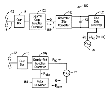
FIG. 4 illustrates a wind turbine 150 comprising a squirrel cage induction
generator 152 (or another type induction generator) that consumes but cannot
produce
magnetizing current. Thus a conductor 156 extending from the generator 152
receives
magnetizing current from a generator side converter 160 and supplies real
power P (at
a variable frequency dependent on the rotational speed of the induction
generator rotor)
to the generator side converter 160. The generator side converter 160
rectifies the
variable frequency signal to DC. The DC power is supplied to a line-side
converter 162
that outputs real power (P) at 60 Hz and regulates system voltage. If one of
the wind
turbines 134 and 138 of FIG. 3 is configured as the wind turbine 150 of FIG. 4
the
output of the line side converter 162 can be used to damp power oscillations
on the
transmission lines 116 and 124 and the tie line 130 of FIG. 3. The power
oscillations
are damped by controlling one or more of the real output power (PAC) or the
voltage
output. It is noted that changing the voltage of the wind turbine changes the
output
power.
A synchronous generator (such as a permanent magnet synchronous generator)
can be substituted for the induction generator 152 with the same inventive
results. The
generator side converter 160 can be simplified in this embodiment as it is not
required
to provide magnetizing current to the generator.
FIG. 5 illustrates another wind turbine design including a doubly-fed
induction
generator (DFIG) 180, with a rotor converter 184 supplying power (P 1 to a
rotor
v rotor/ --
winding of the DFIG 180. A stator of the DFIG connects directly to the grid
28. The
rotor converter 184 also may also generate reactive power Q as illustrated,
without
providing real power. The rotor converter is typically about one-third the
size of a
generator-side or line-side converter used in other wind turbine systems.
A control scheme for controlling the line side converter or rotor converter,
as
described above, is described with reference to FIG. 6. A reference parameter
(frequency, real power, integral of accelerating power, or any other quantity
as known
by those skilled in the art), a monitored (controlled) parameter and a
supplemental
control signal are input to a combiner 200. A lead or lag term may be
associated with
the supplemental control signal as indicated. The resulting combined signal,
referred to
as a control signal, is used to control the converter. For example, the
control signal
CA 02780327 2012-05-08
WO 2011/059706 PCT/US2010/054247
12
may control a voltage regulator to produce a desired voltage signal to damp
the
undesired oscillations. As is known to those skilled in the art, various power
system
parameters can be used to generate the control signal.
While various embodiments of the present invention have been shown and
described herein, it will be obvious that such embodiments are provided by way
of
example only. Numerous variations, changes and substitutions may be made
without
departing from the invention herein. Accordingly, it is intended that the
invention be
limited only by the spirit and scope of the appended claims.