Note: Descriptions are shown in the official language in which they were submitted.
CA 02780354 2012-05-07
WO 2011/142785 PCT/US2010/060358
FLAME-RESISTANT COMPOSITE MATERIALS AND ARTICLES CONTAINING
CARBON NANOTUBE-INFUSED FIBER MATERIALS
CROSS-REFERENCE TO RELATED APPLICATIONS
[0001] This application claims the benefit of priority under 35 U.S.C. 119
from
United States Provisional Patent Application serial number 61/286,340, filed
December 14,
2009, which is incorporated herein by reference in its entirety. This
application is also
related to United States Patent Application serial numbers 12/611,073,
12/611,101 and
12/611,103, all filed on November 2, 2009, each of which is incorporated
herein by reference
in its entirety.
STATEMENT REGARDING FEDERALLY SPONSORED RESEARCH OR
DEVELOPMENT
[0002] Not applicable.
FIELD OF THE INVENTION
[0003] The present invention generally relates to composite materials and,
more
specifically, composite materials containing carbon nanotubes.
BACKGROUND
[0004] Flame resistance is a characteristic of a material causing it to self-
extinguish
upon removal of an ignition source. A commonly used test for quantifying flame
resistance
is ASTM D6413 (Standard Test Method for Flame Resistance of Textiles). In a
garment or
similar textile-containing article, a flame-resistant fabric can dramatically
reduce bodily
tissue damage and increase survival rates for the wearer. Likewise, when used
in structural
applications, a self-extinguishing, flame-resistant composite material can
undergo
significantly less, perhaps even superficial, damage compared to that
experienced by a
comparable composite material that is not flame-resistant. Although flame-
resistant
-1-
CA 02780354 2012-05-07
WO 2011/142785 PCT/US2010/060358
composite materials have garnered significant interest for structural
applications, there
remains a need for further development of these systems.
[0005] A number of factors have hampered the development and implementation of
flame-resistant composite materials. Although the polymer matrix of a
composite material
can be treated with a number of flame retardant agents suitable for imparting
flame resistance
(e.g., bromine, halogen compounds, metal hydroxides, metal hydrates,
transition metal
compounds and phosphorus-nitrogen compounds), a number of these compounds have
known health hazards. An even more significant issue with these flame
retardant agents is
that they are known to adversely impact the structural properties of a
composite material,
thereby limiting range of applications in which the composite material can be
used. In
addition to flame retardant agents, secondary coatings and/or insulation
materials can be
added to a composite material to confer flame resistance. However, these
protective
measures add unwanted weight and bulkiness to the composite material, thereby
making the
composite material unsuitable for many high performance applications. Further,
addition of
secondary coatings and insulation materials leads to increased production
costs. Although
some polymer matrices have inherent flame resistance (e.g., phenolic resins),
composite
materials based on these polymer matrices are not typically used for
structural applications
due their relative low mechanical strength.
[0006] In view of the foregoing, flame-resistant composite materials that
maintain
mechanical properties suitable for high performance structural applications
would be of
substantial benefit in the art. The embodiments described herein satisfy this
need and
provide related advantages as well. Features described herein that confer
flame resistance to
a composite material can also be exploited to prepare flame-resistant articles
and textiles for
non-structural applications.
SUMMARY
[0007] In some embodiments, flame-resistant composite materials described
herein
contain an outer layer and at least one inner layer. The outer layer has an
exterior surface
and contains a first polymer matrix and a first carbon nanotube-infused fiber
material. The
first carbon nanotube-infused fiber material contains a first plurality of
carbon nanotubes and
-2-
CA 02780354 2012-05-07
WO 2011/142785 PCT/US2010/060358
a first fiber material, where the first plurality of carbon nanotubes are
greater than about 50
m in length. The at least one inner layer contains a second polymer matrix.
[0008] In some embodiments, flame-resistant composite materials described
herein
contain an epoxy matrix having an outer layer and at least one inner layer, a
first carbon
nanotube-infused fiber material in the outer layer, and a second carbon
nanotube-infused
fiber material in the at least one inner layer. The outer layer has an
exterior surface and a
thickness that ranges between about 0.005" and about 0.1". The first carbon
nanotube-
infused fiber material contains a first plurality of carbon nanotubes and a
first fiber material,
where the first plurality of carbon nanotubes are greater than about 50 m in
length. The
second carbon nanotube-infused fiber material contains a second plurality of
carbon
nanotubes and a second fiber material.
[0009] In other embodiments, flame-resistant articles described herein contain
an
outer layer and an interior layer. The outer layer has an exterior surface and
contains a
carbon nanotube-infused fiber material. The carbon nanotube-infused fiber
material contains
a plurality of carbon nanotubes and a fiber material. The interior layer is
integral to the outer
layer and includes a textile that lacks carbon nanotubes.
[0010] The foregoing has outlined rather broadly the features of the present
disclosure in order that the detailed description that follows can be better
understood.
Additional features and advantages of the disclosure will be described
hereinafter, which
form the subject of the claims.
BRIEF DESCRIPTION OF THE DRAWINGS
[0011] For a more complete understanding of the present disclosure, and the
advantages thereof, reference is now made to the following descriptions to be
taken in
conjunction with the accompanying drawings describing specific embodiments of
the
disclosure, wherein:
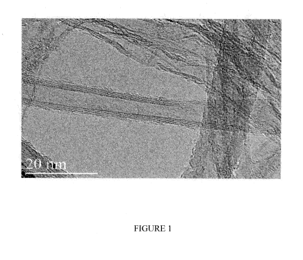
[0012] FIGURE 1 shows an illustrative TEM image of carbon nanotubes that have
been infused to carbon fibers;
-3-
CA 02780354 2012-05-07
WO 2011/142785 PCT/US2010/060358
[0013] FIGURE 2 shows an illustrative SEM image of a carbon fiber that has
been
infused with carbon nanotubes, where the carbon nanotubes are within + 20% of
a targeted
length of 40 m;
[0014] FIGURE 3 shows an illustrative SEM image of a fiber tow within a fabric
weave of carbon nanotube-infused carbon fibers;
[0015] FIGURE 4 shows a schematic of a roving having a plurality of fiber
tows,
each containing a plurality of fibers; and
[0016] FIGURE 5 shows an illustrative chemical process through which carbon
nanotube-infused fiber materials having substantially parallel aligned carbon
nanotubes can
be prepared.
DETAILED DESCRIPTION
[0017] The present disclosure is directed, in part, to flame-resistant
composite
materials and textiles containing carbon nanotube-infused fiber materials. The
present
disclosure is also directed, in part, to flame-resistant articles containing
carbon nanotube-
infused fiber materials and a textile that lacks carbon nanotubes.
[0018] In a composite material containing a fiber material and a polymer
matrix,
physical and/or chemical properties of the fiber material are imparted to the
polymer matrix
to produce a hybrid material having desirable features of both components. In
the present
composite materials, flame resistances of both the fiber material and the
polymer matrix can
be improved by the infusion of carbon nanotubes to the fiber material, and
beneficial
mechanical properties are maintained as in conventional composite materials.
Advantageously, the composite materials and articles of the present disclosure
have
improved flame resistance without a requirement for adding costly or toxic
flame retardant
agents and/or additional thermal shielding.
[0019] Without being bound by theory or mechanism, Applicants believe that the
improved flame resistance of the present composite materials and articles is
due to the
thermo-oxidative stability of carbon nanotubes and their density of coverage
on carbon
-4-
CA 02780354 2012-05-07
WO 2011/142785 PCT/US2010/060358
nanotube-infused fiber materials. By including a sufficient amount of suitable
carbon
nanotubes infused to a fiber material in the outer layer of the present flame-
resistant
composite materials and articles, an effective flame barrier can be formed.
This flame barrier
forms a sacrificial char layer on the exterior surface of the composite
materials and articles in
the presence of an ignition source but with minimal heat transfer occurring to
and thermal
decomposition occurring in the inner layer(s). Although, the outer layer can
be damaged by
the formation of char, the interior portions of the composite material and
articles can remain
relatively undamaged, and negligible impacts to structural properties can
result.
[0020] In addition to their flame resistant-properties, carbon nanotube-
infused fiber
materials are a versatile platform for introducing carbon nanotubes into a
composite matrix.
Using carbon nanotube-infused fiber materials in composite materials allows
significant
problems associated with carbon nanotube incorporation therein to be overcome.
Furthermore, by varying the length and coverage density of carbon nanotubes
infused to the
fiber material, different properties of the carbon nanotubes can be
selectively conveyed to a
composite material. For example, shorter carbon nanotubes are more typically
suitable for
enhancing structural properties of a composite material. Although longer
carbon nanotubes
can also convey structural support, they are more effectively used to
establish an electrically
or thermally conductive percolation pathway in a composite material. In
addition, longer
carbon nanotubes are believed to convey the best flame resistance in the
composite materials
and articles of the present disclosure. Non-uniform or gradient placement of
the carbon
nanotube-infused fiber materials in different regions of the composite
material can be used to
selectively convey a desired property, such as flame resistance, to a given
region of a
composite material.
[0021] As used herein, the term "fiber material" refers to any material that
has a
fibrous component as a basic structural component. The term encompasses
continuous or
non-continuous fibers, filaments, yarns, tows, tapes, woven and non-woven
fabrics, plies,
mats, and the like.
[0022] As used herein, the term "infused" refers to being bonded and
"infusion"
refers to the process of bonding. As such, a carbon nanotube-infused fiber
material refers to
-5-
CA 02780354 2012-05-07
WO 2011/142785 PCT/US2010/060358
a fiber material that has carbon nanotubes bonded thereto. Such bonding of
carbon
nanotubes to a fiber material can involve mechanical attachment, covalent
bonding, ionic
bonding, pi-pi interactions, and/or van der Waals force-mediated
physisorption. In some
embodiments, the carbon nanotubes are directly bonded to the fiber material.
In other
embodiments, the carbon nanotubes are indirectly bonded to the fiber material
via a barrier
coating and/or a catalytic nanoparticle used to mediate growth of the carbon
nanotubes. The
particular manner in which the carbon nanotubes are infused to the fiber
material can be
referred to as the bonding motif.
[0023] As used herein, the terms "flame resistant" or "flame resistance" refer
to a
material that is at least partially self-extinguishing when a source of
ignition is removed.
[0024] As used herein, the term "nanoparticle" refers to particles having a
diameter
between about 0.1 nm and about 100 nm in equivalent spherical diameter,
although the
nanoparticles need not necessarily be spherical in shape.
[0025] As used herein, the terms "sizing agent," or "sizing," collectively
refer to
materials used in the manufacture of fiber materials that act as a coating to
protect the
integrity of the fiber material, to provide enhanced interfacial interactions
between the fiber
material and a composite matrix, and/or to alter and/or to enhance certain
physical properties
of the fiber material.
[0026] As used herein, the term "spoolable dimensions" refers to fiber
materials that
have at least one dimension that is not limited in length, thereby allowing
the fiber material
to be stored on a spool or mandrel following infusion with carbon nanotubes.
Fiber materials
of "spoolable dimensions" have at least one dimension that indicates the use
of either batch
or continuous processing for carbon nanotube infusion to the fiber material.
An illustrative
carbon fiber material of spoolable dimensions that is commercially available
is AS4 12k
carbon fiber tow with a tex value of 800 (1 tex = 1 g/1,000m) or 620 yard/lb
(Grafil, Inc.,
Sacramento, CA). Commercial carbon fiber tow, in particular, can be obtained
in 5, 10, 20,
50, and 100 lb. spools, for example, although larger spools can require
special order.
-6-
CA 02780354 2012-05-07
WO 2011/142785 PCT/US2010/060358
[0027] As used herein, the term "transition metal" refers to any element or
alloy of
elements in the d-block of the periodic table (Groups 3 through 12), and the
term "transition
metal salt" refers to any transition metal compound such as, for example,
transition metal
oxides, carbides, nitrides, and the like. Illustrative transition metals that
form catalytic
nanoparticles suitable for synthesizing carbon nanotubes include, for example,
Ni, Fe, Co,
Mo, Cu, Pt, Au, Ag, alloys thereof, salts thereof, and mixtures thereof.
[0028] As used herein, the term "uniform in length" refers to a condition in
which
carbon nanotubes have lengths with tolerances of plus or minus about 20% or
less of the total
carbon nanotube length, for carbon nanotube lengths ranging between about 1 m
to about
500 m. At very short carbon nanotube lengths (e.g., about 1 m to about 4
m), the
tolerance can be plus or minus about 1 m, that is, somewhat more than about
20% of the
total carbon nanotube length.
[0029] As used herein, the term "uniform in density distribution" refers to a
condition
in which the carbon nanotube density on a fiber material has a tolerance of
plus or minus
about 10% coverage over the fiber material surface area that is covered by
carbon nanotubes.
[0030] As used herein, the term "polymer matrix" refers to a bulk polymer
material
than can organize carbon nanotube-infused fiber materials into particular
orientations,
including random orientations, aligned orientations, perpendicular
orientations, parallel
orientations, and combinations thereof.
[0031] In some embodiments, flame-resistant composite materials of the present
disclosure contain an outer layer and at least one inner layer. The outer
layer has an exterior
surface and contains a first polymer matrix and a first carbon nanotube-
infused fiber material.
The first carbon nanotube-infused fiber material contains a first plurality of
carbon nanotubes
and a first fiber material, where the first plurality of carbon nanotubes are
greater than about
50 m in length. The at least one inner layer contains a second polymer
matrix. In some
embodiments, the at least one inner layer further includes a second carbon
nanotube-infused
fiber material that contains a second plurality of carbon nanotubes and a
second fiber
material, where the second plurality of carbon nanotubes are less than about
50 m in length.
-7-
CA 02780354 2012-05-07
WO 2011/142785 PCT/US2010/060358
[0032] In some embodiments, flame-resistant composite materials of the present
disclosure contain an epoxy matrix having an outer layer and an inner layer, a
first carbon
nanotube-infused fiber material in the outer layer, and a second carbon
nanotube-infused
fiber material in the inner layer. The outer layer has an exterior surface and
a thickness that
ranges between about 0.005" and about 0.1". The first carbon nanotube-infused
fiber
material contains a first plurality of carbon nanotubes and a first fiber
material, where the first
plurality of carbon nanotubes are greater than about 50 m in length. The
second carbon
nanotube-infused fiber material contains a second plurality of carbon
nanotubes and a second
fiber material.
[0033] Fiber materials that have been infused with carbon nanotubes, including
carbon fibers, ceramic fibers, metal fibers, and glass fibers, are described
in Applicants' co-
pending United States Patent applications 12/611,073, 12/611,101, and
12/611,103, all filed
on November 2, 2009, each of which is incorporated herein by reference in its
entirety.
Additional details concerning the infusion of carbon nanotubes to a fiber
material are set forth
in further detail hereinbelow. FIGURE 1 shows an illustrative TEM image of
carbon
nanotubes that have been infused to carbon fibers. FIGURE 2 shows an
illustrative SEM
image of a carbon fiber that has been infused with carbon nanotubes, where the
carbon
nanotubes are within +20% of a targeted length of 40 m. In the images of
FIGURES 1 and
2, the carbon nanotubes are multi-wall carbon nanotubes, although any carbon
nanotubes
such as single-wall carbon nanotubes, double-wall carbon nanotubes, and multi-
wall carbon
nanotubes having more than two walls can be infused to the fiber materials in
the present
flame-resistant composite materials and articles. In general, single-wall
carbon nanotubes
have a better thermal conductivity than do carbon nanotubes having more than
one wall, but
the overall performance of infused carbon nanotubes in the present embodiments
can be a
function of their thermo-oxidative stability in addition to their thermal
conductivity.
Although FIGURES 1 and 2 show the infusion of carbon nanotubes to a carbon
fiber
material, these images are merely illustrative of a type of fiber material
that can be infused
with carbon nanotubes and included in the present composite materials and
articles. In
various embodiments, fiber materials that can be infused with carbon nanotubes
and included
in the present flame-resistant composite materials and articles include, for
example, glass
-8-
CA 02780354 2012-05-07
WO 2011/142785 PCT/US2010/060358
fibers, carbon fibers, ceramic fibers, and organic fibers (e.g., aramid
fibers). In embodiments
in which both a first fiber material and a second fiber material are present,
the first fiber
material and the second fiber material can be independently selected from
fibers such as, for
example, carbon fibers, ceramic fibers, glass fibers, organic fibers, or any
combination
thereof.
[0034] There are three types of carbon fibers that are categorized based on
the
precursors used to generate the fibers, any of which can be used in the
various embodiments
described herein: Rayon, Polyacrylonitrile (PAN) and Pitch. Carbon fibers from
rayon
precursors, which are cellulosic materials, have a relatively low carbon
content of about 20%,
and the fibers tend to have a low strength and stiffness. In contrast, PAN
precursors provide
carbon fibers having a carbon content of about 55% and an excellent tensile
strength due to a
minimum of surface defects. Pitch precursors based on petroleum asphalt, coal
tar, and
polyvinyl chloride can also be used to produce carbon fibers. Although pitches
are relatively
low in cost and high in carbon yield, there can be issues of non-uniformity in
a given batch of
the resultant carbon fibers.
[0035] The types of carbon nanotubes infused to the fiber materials of the
present
flame-resistant composite materials and articles can generally vary without
limitation. In
various embodiments, the carbon nanotubes infused to the fiber material can
be, for example,
any of a number of cylindrically-shaped allotropes of carbon of the fullerene
family including
single-walled carbon nanotubes (SWNTs), double-walled carbon nanotubes
(DWNTs), multi-
walled carbon nanotubes (MWNTs), and any combination thereof. In some
embodiments,
the carbon nanotubes can be capped with a fullerene-like structure. Stated
another way, the
carbon nanotubes have closed ends in such embodiments. However, in other
embodiments,
the carbon nanotubes remain open-ended. In some embodiments, the carbon
nanotubes
encapsulate other materials. In some embodiments, the carbon nanotubes are
covalently
functionalized after becoming infused to the fiber material. Functionalization
can be used to
increase the compatibility of the carbon nanotubes with certain polymer
matrices. In some
embodiments, a plasma process can be used to promote functionalization of the
carbon
nanotubes.
-9-
CA 02780354 2012-05-07
WO 2011/142785 PCT/US2010/060358
[0036] Carbon nanotube lengths infused to a fiber material can vary over a
wide
range. In some embodiments, an average length of infused carbon nanotubes is
between
about 1 m and about 10 m. Carbon nanotubes having such lengths can be
useful, for
example, in applications to increase shear strength. In other embodiments, an
average length
of infused carbon nanotubes is between about 5 m and about 70 m. Carbon
nanotubes
having such lengths can be useful in applications including, for example,
increased tensile
strength, particularly if the carbon nanotubes are aligned substantially
parallel with the
longitudinal axis of the fiber material. In still other embodiments, an
average length of
infused carbon nanotubes is between about 10 m and about 100 m. Carbon
nanotubes
having such lengths can be useful, for example, to improve electrical and
thermal
conductivity properties, in addition to mechanical properties. In some
embodiments, an
average length of infused carbon nanotubes is between about 100 [tm and about
500 m.
Carbon nanotubes having such lengths can be particularly beneficial to improve
electrical and
thermal conductivity properties, for example.
[0037] In various embodiments of the present flame-resistant composite
materials, the
first plurality of carbon nanotubes infused to the first fiber material of the
outer layer are
greater than about 50 m in length. Applicants have discovered that in
composite materials,
shorter carbon nanotubes (i.e., carbon nanotubes that are less than about 50
m in length)
offer a greater degree of structural reinforcement per unit weight than do
longer carbon
nanotubes (i.e., carbon nanotubes that are greater than about 50 m in
length). Although
longer carbon nanotubes can provide some degree of structural reinforcement,
they do so at a
cost of increased weight in the composite material, which can be unsuitable
for certain high
performance applications. However, Applicants have discovered that longer
carbon
nanotubes are especially well suited for conferring flame resistance to a
composite material.
By including longer carbon nanotubes in the outer layer of the present flame-
resistant
composite materials, Applicants have developed a composite material that
maintains good
structural properties and light weight, while having good flame-resistance on
its exterior. In
some embodiments, the first plurality of carbon nanotubes infused to the first
fiber material
of the outer layer are between about 50 m and about 100 m in length. In
other
embodiments, first plurality of carbon nanotubes infused to the first fiber
material of the outer
-10-
CA 02780354 2012-05-07
WO 2011/142785 PCT/US2010/060358
layer are greater than about 100 m in length, or greater than about 200 m in
length, or
greater than about 300 m in length, or greater than about 400 m in length,
or greater than
about 500 m in length, or any subrange in between any of these values.
[00381 In some embodiments of the present flame-resistant composite materials,
the
at least one inner layer can also include at least one component such as a
second fiber
material, a second carbon nanotube-infused fiber material containing a second
plurality of
carbon nanotubes and a second fiber material, and various combinations
thereof. In some
embodiments, the first fiber material and the second fiber material are the
same. In other
embodiments, the first fiber material and the second fiber material are
different. In some
embodiments, the fiber material in the at least one inner layer lacks carbon
nanotubes. For
example, the flame-resistant composite materials of the present disclosure in
various
embodiments can contain carbon nanotube-infused carbon fibers, carbon nanotube-
infused
glass fibers, carbon nanotube-infused ceramic fibers, and/or carbon nanotube-
infused organic
fibers in the outer layer, while the at least one inner layer contains carbon
fibers, glass fibers,
ceramic fibers, and/or organic fibers that lack carbon nanotube infusion.
However, the flame-
resistant composite materials of the present disclosure in other various
embodiments can
contain carbon nanotube-infused carbon fibers, carbon nanotube-infused glass
fibers, carbon
nanotube-infused ceramic fibers, and/or carbon nanotube-infused organic fibers
in the outer
layer, while the at least one inner layer also contains carbon nanotube-
infused carbon fibers,
carbon nanotube-infused glass fibers, carbon nanotube-infused ceramic fibers,
and/or carbon
nanotube-infused organic fibers. Mixtures of carbon nanotube-infused fiber
materials and
fiber materials lacking carbon nanotube infused can also be contained in the
at least one inner
layer.
[00391 In some embodiments, the second plurality of carbon nanotubes infused
to the
second fiber material of the inner layer(s) have a length that is less than
that of the first
plurality of carbon nanotubes. This feature allows the carbon nanotubes in the
second carbon
nanotube-infused fiber material to be directed more toward structural
reinforcement or
another property of the composite material (e.g., tensile strength, Young's
Modulus, shear
strength, shear modulus, toughness, compression strength, compression modulus,
density,
electromagnetic wave absorptivity/reflectivity, acoustic transmittance,
electrical conductivity,
-11-
CA 02780354 2012-05-07
WO 2011/142785 PCT/US2010/060358
and/or thermal conductivity) rather than toward conferring flame resistance,
for example.
Further, it avoids the addition of unnecessary weight to the flame-resistant
composite
material where flame resistance is not needed. In some embodiments, the second
plurality of
carbon nanotubes are less than about 50 m in length. In other embodiments,
the second
plurality of carbon nanotubes are less than about 20 m in length. In still
other embodiments,
the second plurality of carbon nanotubes are between about 1 m and about 10
m in length.
[0040] In alternative embodiments, however, the second plurality of carbon
nanotubes can have a length that is greater than or equal to that of the first
plurality of carbon
nanotubes. For example, in some embodiments, the second plurality of carbon
nanotubes are
greater than about 50 m in length. Having longer carbon nanotubes in the
inner layer(s) of a
composite material might be desirable, for example, when an electrically or
thermally
conductive flame-resistant composite material is needed. In such embodiments,
the first
plurality of carbon nanotubes in the outer layer are operable to convey flame
resistance to the
composite material, and the second plurality of carbon nanotubes in the inner
layer(s) are
operable to establish an electrically or thermally conductive percolation
pathway within the
composite material, which could remain intact even after the outer layer is
sacrificed in a
flame event.
[0041] In still other alternative embodiments, the second plurality of carbon
nanotubes of the inner layer(s) can contain a mixture of carbon nanotube
lengths, some of
which are longer than that of the first plurality of carbon nanotubes and some
of which are
shorter. In such embodiments, the longer carbon nanotubes of the inner
layer(s) are operable
to establish an electrically or thermally conductive percolation pathway
within the composite
material, while the shorter carbon nanotubes of the inner layer(s) are
operable, for example,
to enhance the structural properties of the composite material. As a non-
limiting example, in
some embodiments the first plurality of carbon nanotubes are greater than
about 50 m in
length, and the second plurality of carbon nanotubes includes a portion of
carbon nanotubes
that are less than about 50 m in length and a portion of carbon nanotubes
that are greater
than about 50 m in length.
-12-
CA 02780354 2012-05-07
WO 2011/142785 PCT/US2010/060358
[0042] As noted above, the present flame-resistant composite materials can
have their
flame resistance properties primarily conferred to their outer layer in order
to limit impacts on
structural performance elsewhere in the composite material. When exposed to a
flame
condition, the outer layer of the present composite materials can form a
sacrificial char layer
that discourages further burning upon removal of an ignition source. Under
these conditions,
the inner layer(s) of the composite material can remain substantially
unaffected, and the
structural properties of the composite material can remain essentially
unperturbed.
[0043] The thickness of the composite material's outer layer can be tailored
to
specific applications having a wide range of ignition conditions. For example,
in high
temperature applications having intense flames, thicker outer layers can
provide better flame
resistance. However, if the exposure time to the ignition conditions is
relatively short or the
flame is not particularly intense, a thinner outer layer can suffice. In some
embodiments, the
thickness of the outer layer ranges between about 0.005" and about 0.1" In
other
embodiments, the thickness of the outer layer ranges between about 0.005" and
about 0.015"
or between about 0.015" and about 0.05". In still other embodiments, the
thickness of the
outer layer ranges between about 0.1" and about I".
[0044] In some embodiments, the first plurality of carbon nanotubes is present
in an
amount ranging between about 0.1% and about 20% of the outer layer by weight.
In other
embodiments, the first plurality of carbon nanotubes is present in an amount
between about
0.1% and about 5% or between about 5% and about 10% of the outer layer by
weight.
Control over the amount of carbon nanotubes in the outer layer can allow the
degree of flame
resistance to be tailored to a specific application.
[0045] When present, the second plurality of carbon nanotubes can be present
in an
amount ranging between about 0.1 % and about 10% of the at least one inner
layer by weight.
In other embodiments, the second plurality of carbon nanotubes is present in
an amount
ranging between about 0.1% and about 3% or between about 3% and about 5% of
the at least
one inner layer by weight. Among other properties, control over the amount of
carbon
nanotubes in the at least one inner layer can modify the mechanical properties
of the
composite material to be suited for a particular application.
-13-
CA 02780354 2012-05-07
WO 2011/142785 PCT/US2010/060358
[0046] In various embodiments of the present disclosure, the second plurality
of
carbon nanotubes, when present, can form a lower weight percentage of the
flame-resistant
composite material than does the first plurality of carbon nanotubes. In such
embodiments,
high concentrations of carbon nanotubes, including those noted above, can be
used in the
outer layer, while lower concentrations can be used in the at least one inner
layer to address a
desired property such as, for example, structural reinforcement. In various
embodiments, the
first plurality of carbon nanotubes and the second plurality of carbon
nanotubes are
collectively present in an amount that is less than about 20% of the flame-
resistant composite
material by weight. In some embodiments, the first plurality of carbon
nanotubes and the
second plurality of carbon nanotubes are collectively present in an amount
ranging between
about 0.1% and about 10% of the flame resistant composite material by weight.
In other
embodiments, the first plurality of carbon nanotubes and the second plurality
of carbon
nanotubes are collectively present in an amount ranging between about 0.5% and
about 9%
of the flame-resistant composite material by weight or between about 1% and
about 7.5% of
the flame-resistant composite material by weight, including all subranges in
between these
values. One of ordinary skill in the art with the benefit of this disclosure
will recognize that
the flame resistance of the outer layer and the mechanical properties of the
at least one inner
layer can be tailored to include a suitable amount of carbon nanotubes to
optimize each
property, while keeping the total carbon nanotube concentration within the
above ranges.
[0047] Polymer matrices that can be used to form the present flame-resistant
composite materials can be any polymer matrix that is typically used in
conventional fiber-
reinforced polymer composite materials. In some embodiments, the first polymer
matrix and
the second polymer matrix are the same. This condition assures a maximized
compatibility
between the outer layer and the at least one inner layer, which often
generates optimal
structural properties. However, in alternative embodiments, the first polymer
matrix and the
second polymer matrix are different. One of ordinary skill in the art will
recognize certain
conditions under which one could benefit from having different identities for
the first
polymer matrix and the second polymer matrix. For example, in certain
applications, it might
be beneficial to have a thin outer layer containing a heavy, impact resistant
polymer matrix
and less dense inner layers containing a different polymer matrix.
-14-
CA 02780354 2012-05-07
WO 2011/142785 PCT/US2010/060358
[0048] In some embodiments, suitable polymer matrices can include, for
example, an
epoxy, a polyester, a vinylester, a polyetherimide, a polyetherketoneketone, a
polyphthalamide, a polyetherketone, a polyetheretherketone, a polyimide, a
phenol-
formaldehyde, or a bismaleimide. More generally, thermoplastic polymers,
thermosetting
polymers and elastomeric polymers are suitable polymer matrices. Suitable
thermosetting
polymer matrices include, for example, phthalic/maelic type polyesters, vinyl
esters, epoxies,
phenolics, cyanates, bismaleimides, and nadic end-capped polyimides (e.g., PMR-
15).
Suitable thermoplastic polymer matrices include, for example, polysulfones,
polyamides,
polycarbonates, polyphenylene oxides, polysulfides, polyether ether ketones,
polyether
sulfones, polyamide-imides, polyetherimides, polyimides, polyarylates, and
liquid crystalline
polyesters.
[0049] In some embodiments, both the first polymer matrix and the second
polymer
matrix are an epoxy. One of ordinary skill in the art will recognize that
epoxy matrices are
commonly included in composite materials that are used in structural
applications, and many
of these epoxy matrices are suitable for inclusion in the present flame-
resistant composite
materials. In general, epoxies are curable by reacting an epoxide group
therein. Further,
epoxies can be a two-component epoxy or self-curable.
[0050] The form of the fiber material used in the present flame-resistant
composite
materials can vary over a wide range. In various embodiments, the fiber
material can be in
non-limiting forms of continuous or non-continuous filaments, rovings, yarns,
fiber tows,
tapes, fiber-braids, woven fabrics, non-woven fabrics, fiber plies (e.g.,
unidirectional fiber
plies), and other three-dimensional woven or non-woven structures. For
example, in
embodiments in which the fiber material is a carbon fiber, the fiber material
can be in non-
limiting forms including a continuous or non-continuous carbon filament,
carbon roving,
carbon fiber yarn, carbon fiber tow, carbon tape, carbon fiber-braid, woven
carbon fabric,
non-woven carbon fiber mat, carbon fiber ply, and other three-dimensional
woven or non-
woven structures. FIGURE 3 shows an illustrative SEM image of a fiber tow
within a fabric
weave of carbon nanotube-infused carbon fibers. In various embodiments, carbon
nanotubes
of uniform length and distribution can be infused to spoolable lengths of
filaments, fiber
tows, tapes, fabrics and other three-dimensional woven structures. While
various filaments,
-15-
CA 02780354 2012-05-07
WO 2011/142785 PCT/US2010/060358
fiber tows, yarns, mats, woven and non-woven fabrics and the like can be
directly infused
with carbon nanotubes, it is also possible to generate such higher ordered
structures from the
parent fiber tow, yarn or the like from carbon nanotube-infused fibers. For
example, a carbon
nanotube-infused fiber material can be transformed into a woven fabric from a
carbon
nanotube-infused fiber tow. In some embodiments, woven fabrics can contain a
mixture of
fiber types such as, for example, a mixture of carbon fibers, glass fibers,
ceramic fibers,
and/or organic fibers.
[0051] Filaments include high aspect ratio fibers having diameters generally
ranging
in size between about 1 m and about 100 m. Rovings include soft strands of
fiber that
have been twisted, attenuated and freed of foreign matter.
[0052] Fiber tows are generally compactly associated bundles of filaments,
which can
be twisted together to give yarns in some embodiments. Yams include closely
associated
bundles of twisted filaments, wherein each filament diameter in the yarn is
relatively
uniform. Yarns have varying weights described by their `tex,' (expressed as
weight in grams
per 1000 linear meters), or `denier' (expressed as weight in pounds per 10,000
yards). For
yarns, a typical tex range is usually between about 200 and about 2000.
[0053] Fiber braids represent rope-like structures of densely packed fibers.
Such
rope-like structures can be assembled from yarns, for example. Braided
structures can
include a hollow portion. Alternately, a braided structure can be assembled
about another
core material.
[0054] Fiber tows can also include associated bundles of untwisted filaments.
As in
yarns, filament diameter in a fiber tow is generally uniform. Fiber tows also
have varying
weights and a tex range that is usually between about 200 and 2000. In
addition, fiber tows
are frequently characterized by the number of thousands of filaments in the
fiber tow, such
as, for example, a 12K tow, a 24K tow, a 48K tow, and the like.
[0055] Tapes are fiber materials that can be assembled as weaves or as non-
woven
flattened fiber tows, for example. Tapes can vary in width and are generally
two-sided
structures similar to a ribbon. In the various embodiments described herein,
carbon
-16-
CA 02780354 2012-05-07
WO 2011/142785 PCT/US2010/060358
nanotubes can be infused to the fiber material of a tape on one or both sides
of a tape. In
addition, carbon nanotubes of different types, diameters or lengths can be
grown on each side
of a tape. Tapes having different types, diameters or lengths on each side of
the tape can be
advantageous in some embodiments of the present flame-resistant composite
materials. As
described in Applicants' co-pending United States Patent Applications,
infusion. of carbon
nanotubes to spools of tape can be conducted in a continuous manner.
[0056] In some embodiments, fiber materials can be organized into fabric or
sheet-
like structures. These include, for example, woven fabrics, non-woven fiber
mats and fiber
plies, in addition to the tapes described above. Such higher ordered
structures can be
assembled from parent fiber tows, yarns, filaments or the like, with carbon
nanotubes already
infused on the fiber material. As with tapes, such structures can also serve
as a substrate for
continuous infusion of carbon nanotubes thereon.
[0057] In some embodiments, carbon nanotubes can be infused to the fiber
material at
the tow or roving level prior to textile weaving. In such embodiments, carbon
nanotubes can
occupy both intra-tow and inter-tow space to achieve a high carbon nanotube
loading.
FIGURE 4 shows a schematic of a roving 400 having a plurality of fiber tows
401, each
containing a plurality of fibers 405. Inter-tow spaces 402 and inter-tow
spaces 403 are
illustrated in the FIGURE. In alternative embodiments, infusion with carbon
nanotubes can
take place according to the procedures described herein after weaving a tow or
roving into a
specified weave architecture.
[0058] Carbon nanotube-infused fiber materials prepared according to the
processes
described herein have much higher carbon nanotube loading percentages than are
produced
by other methods. This feature allows the composite materials of the present
disclosure to
contain much higher loading percentages of carbon nanotubes than are
attainable in
composite materials produced by more conventional techniques. In particular,
carbon
nanotube-infused fiber materials allow a well-blended carbon nanotube
composite material to
be attained. In general, the carbon nanotube-infused fiber materials of the
present disclosure
can contain between about 1% and about 30% carbon nanotubes by weight. In some
embodiments, up to 40% carbon nanotubes by weight can be infused to the fiber
material. In
-17-
CA 02780354 2012-05-07
WO 2011/142785 PCT/US2010/060358
various embodiments, the first carbon nanotube-infused fiber material of the
outer layer
contains between about 1% and about 30% carbon nanotubes by weight. When
present, the
second carbon nanotube-infused fiber material of the at least one inner layer
can also contain
between about 1% and about 30% carbon nanotubes by weight, or a different
range of carbon
nanotube weights, if desired.
[0059] As described in Applicants' co-pending applications, a fiber material
is
modified to provide a layer (typically no more than a monolayer) of catalytic
nanoparticles on
the fiber material for the purpose of growing carbon nanotubes thereon. In
various
embodiments, the catalytic nanoparticles used for facilitating carbon nanotube
growth are
transition metals and various salts thereof. In some embodiments, the
catalytic nanoparticles
can be deposited on the fiber material using techniques such as, for example,
dip coating,
spray coating, plasma deposition, evaporation techniques, electrolytic
deposition techniques,
and other processes known to those of ordinary skill in the art.
[0060] Carbon nanotubes can be metallic, semimetallic or semiconducting
depending
on their chirality. An established system of nomenclature for designating a
carbon
nanotube's chirality is recognized by those of ordinary skill in the art and
is distinguished by
a double index (n,m), where n and in are integers that describe the cut and
wrapping of
hexagonal graphite when formed into a tubular structure. In addition to their
chirality, a
carbon nanotube's diameter also influences its electrical conductivity and the
related property
of thermal conductivity. In the synthesis of carbon nanotubes, the carbon
nanotube's
diameter can be controlled by using catalytic nanoparticles of a given size.
Typically, a
carbon nanotube's diameter is approximately that of the catalytic nanoparticle
that catalyzes
its formation. Therefore, the carbon nanotube's properties can be additionally
controlled by,
for example, adjusting the size of the catalytic nanoparticles used to
synthesize the carbon
nanotubes. By way of non-limiting example, catalytic nanoparticles having a
diameter of
about 1 nm can be used to infuse a fiber material with single-wall carbon
nanotubes. Larger
catalytic nanoparticles can be used to prepare predominantly multi-wall carbon
nanotubes,
which have larger diameters because of their multiple nanotube layers, or
mixtures of single-
wall and multi-wall carbon nanotubes. Multi-wall carbon nanotubes typically
have a more
complex conductivity profile than do single-wall carbon nanotubes due to
interwall reactions
-18-
CA 02780354 2012-05-07
WO 2011/142785 PCT/US2010/060358
between the individual nanotube layers that can redistribute current non-
uniformly. By
contrast, there is no change in current across different portions of a single-
wall carbon
nanotube.
[0061] In some embodiments, the fiber materials further include a barrier
coating.
Illustrative barrier coatings can include, for example, alkoxysilanes,
methylsiloxanes,
alumoxanes, alumina nanoparticles, spin on glass and glass nanoparticles. For
example, in an
embodiment the barrier coating is Accuglass T-11 Spin-On Glass (Honeywell
International
Inc., Morristown, NJ). In some embodiments, the catalytic nanoparticles for
carbon nanotube
synthesis can be combined with the uncured barrier coating material and then
applied to the
fiber material together. In other embodiments, the barrier coating material
can be added to
the fiber material prior to deposition of the catalytic nanoparticles. In
general, the barrier
coating is sufficiently thin to allow exposure of the catalytic nanoparticles
to a carbon
feedstock gas for carbon nanotube growth. In some embodiments, the thickness
of the barrier
coating is less than or about equal to the effective diameter of the catalytic
nanoparticles. In
some embodiments, the thickness of the barrier coating is in a range between
about 10 nm
and about 100 nm. In other embodiments, the thickness of the barrier coating
is in a range
between about 10 rim and about 50 nm, including 40 nm. In some embodiments,
the
thickness of the barrier coating is less than about 10 nm, including about 1
nm, about 2 nm,
about 3 nm, about 4 nm, about 5 nm, about 6 rim, about 7 nm, about 8 nm, about
9 nm, and
about 10 nm, including all values and subranges therebetween.
[0062] Without being bound by theory, the barrier coating can serve as an
intermediate layer between the fiber material and the carbon nanotubes and
mechanically
infuses the carbon nanotubes to the fiber material. Such mechanical infusion
provides a
robust system in which the fiber material serves as a platform for organizing
the carbon
nanotubes, while allowing the beneficial properties of the carbon nanotubes to
be conveyed to
the fiber material. Moreover, benefits of including a barrier coating include
protection of the
fiber material from chemical damage due to moisture exposure and/or thermal
damage at the
elevated temperatures used to promote carbon nanotube growth.
-19-
CA 02780354 2012-05-07
WO 2011/142785 PCT/US2010/060358
[0063] After deposition of the catalytic nanoparticles, a chemical vapor
deposition
(CVD)-based process or other process for growing carbon nanotubes is used to
continuously
grow carbon nanotubes on the fiber material. The resultant carbon nanotube-
infused fiber
material is itself a composite architecture. Illustrative processes for carbon
nanotube
synthesis include, for example, micro-cavity, thermal or plasma-enhanced CVD
techniques,
laser ablation, arc discharge, and high pressure carbon monoxide (HiPCO)
synthesis, all of
which are known to those of ordinary skill in the art. In some embodiments,
the CVD-based
growth process can be plasma-enhanced by providing an electric field during
the growth
process such that the carbon nanotubes follow the direction of the electric
field.
[0064] In some embodiments, the carbon nanotubes infused to the fiber material
are
substantially perpendicular to the longitudinal axis of the fiber material.
Stated another way,
the carbon nanotubes infused to the fiber material are circumferentially
perpendicular to the
fiber surface. In other embodiments, the carbon nanotubes infused to the fiber
material are
substantially parallel to the longitudinal axis of the fiber material.
[0065] In some embodiments, the carbon nanotubes infused to the fiber material
are
unbundled, thereby facilitating strong interactions between the fiber material
and the carbon
nanotubes. Unbundled carbon nanotubes allow the beneficial carbon nanotube
properties to
be well expressed in the present composite materials. In other embodiments,
the carbon
nanotubes infused to the fiber material can be made in the form of a highly
uniform,
entangled carbon nanotube network by reducing the growth density during carbon
nanotube
synthesis.
[0066] In some embodiments, the carbon nanotubes infused to the fiber material
are
generally uniform in density distribution, referring to the uniformity of the
carbon nanotube
density on the fiber material. As defined above, the tolerance for a uniform
density
distribution is plus or minus about 10% over the fiber material surface area
that is infused
with carbon nanotubes. By way of non-limiting example, this tolerance is
equivalent to about
1500 carbon nanotubes/ m2 for a carbon nanotube having a diameter of 8 nm and
5 walls.
Such a figure assumes that the space inside the carbon nanotube is fillable.
In some
embodiments, the maximum carbon nanotube density, expressed as a percent
coverage of the
-20-
CA 02780354 2012-05-07
WO 2011/142785 PCT/US2010/060358
fiber material (i.e., the percentage of the fiber material surface area that
is covered with
carbon nanotubes) can be as high as about 55%, again assuming a carbon
nanotube having an
8 nm diameter, 5 walls and fillable space within. 55% surface area coverage is
equivalent to
about 15,000 carbon nanotubes/ m2 for a carbon nanotube having the referenced
dimensions.
In some embodiments, the density of carbon nanotube coverage on the fiber
material is up to
about 15,000 carbon nanotubes/ m2. One of ordinary skill in the art will
recognize that a
wide range of carbon nanotube densities can be attained by varying the
disposition of the
catalytic nanoparticles on the surface of the fiber material, the exposure
time to carbon
nanotube growth conditions, and the actual growth conditions themselves used
to infuse the
carbon nanotubes to the fiber material.
[0067] Without being bound by theory or mechanism, Applicants believe that the
flame resistance of the present composite materials is due to the thermo-
oxidative stability of
carbon nanotubes and their density of coverage on the first fiber material in
the outer layer.
The first plurality of carbon nanotubes in the outer layer serve as a thermal
barrier that forms
a sacrificial char layer on the exterior surface of the composite material
without allowing
thermal decomposition to substantially proceed into the inner layer(s) of the
composite
material. In addition, the high thermal conductivity of carbon nanotubes can
be exploited for
channeling heat through the outer layer of the composite material while
limiting thermal
transfer into the inner layer(s). Limiting thermal transfer to the inner
layer(s) can be readily
accomplished by aligning the first plurality of carbon nanotubes substantially
parallel to the
longitudinal axis of the first fiber material. By aligning the first plurality
of carbon nanotubes
in a substantially parallel manner, heat can be channeled along the first
fiber material rather
than into the inner layer(s) of the composite material.
[0068] Once a carbon nanotube-infused fiber material has been formed,
alignment of
the carbon nanotubes on the fiber material in a substantially parallel manner
can be
performed by mechanical means, by electromechanical means, by chemical means,
by
employing a plasma, or other methods known in the art. By way of non-limiting
example, a
carbon nanotube-infused fiber material having the carbon nanotubes
substantially aligned in a
parallel manner can be formed according to methods described in Applicants co-
pending
United States Provisional Patent Application 61/300,783, filed February 2,
2010, which is
-21-
CA 02780354 2012-05-07
WO 2011/142785 PCT/US2010/060358
incorporated herein by reference in its entirety. In some embodiments, the
process of
aligning the carbon nanotubes in a substantially parallel manner can involve
forming pi-
stacking interactions and/or covalent bonds between the carbon nanotubes,
between the
carbon nanotubes and the fiber material, and/or between the carbon nanotubes
and the
polymer matrix. In some embodiments, the process of aligning carbon nanotubes
in a
substantially parallel manner can involve growing multiple layers of carbon
nanotubes on the
fiber material by repeating the carbon nanotube growth steps described herein.
Alternately,
the substantially parallel alignment of carbon nanotubes can take place during
the process of
infusing the fiber material with carbon nanotubes.
[0069] Mechanical means for aligning carbon nanotubes in a substantially
parallel
manner include, for example, extrusion, pultrusion, gas pressure aided dies,
conventional dies
and mandrels. Use of these techniques and other related techniques that apply
a shearing
force in the direction of the longitudinal axis of the fiber material can
realign the carbon
nanotubes in a carbon nanotube-infused fiber material from a substantially
perpendicular
orientation into an orientation that is substantially parallel to the
longitudinal axis of the fiber
material.
[0070] Electromechanical means for aligning carbon nanotubes in a
substantially
parallel manner include, for example, electric or magnetic fields that are
aligned parallel to
the fiber material during carbon nanotube growth, such that the carbon
nanotubes become
substantially aligned parallel to the longitudinal axis of the fiber material
during the growth
process. In forming carbon nanotubes, growth tends to follow the direction of
the applied
electric or magnetic field. By properly adjusting the geometry of the plasma
spray and
electric or magnetic field, carbon nanotube-infused fiber materials having
substantially
parallel aligned carbon nanotubes can be easily formed. This technique
beneficially avoids
having to realign the carbon nanotubes into a substantially parallel alignment
after carbon
nanotube infusion.
[0071] Chemical means for aligning carbon nanotubes include use of solvents,
surfactants, and microemulsions that result in a sheathing effect as the fiber
material is drawn
out of a liquid containing these chemicals. Thus, drawing a carbon nanotube-
infused fiber
-22-
CA 02780354 2012-05-07
WO 2011/142785 PCT/US2010/060358
material from a liquid can realign the carbon nanotubes into a substantially
parallel
orientation. In some embodiments, chemical alignment can also include
crosslinking
between adjacent perpendicularly-aligned carbon nanotubes with a bifunctional
polymer
through formation of covalent bonds and/or pi-stacking interactions. The
crosslinked carbon
nanotubes can then be induced into a substantially parallel alignment through
any of the
aforementioned techniques. A particularly suitable bifunctional polymer for
crosslinking
carbon nanotubes is KENTERA available from Zyvex Technologies.
[0072] FIGURE 5 shows an illustrative chemical process through which carbon
nanotube-infused fiber materials having substantially parallel aligned carbon
nanotubes can
be prepared. Starting with fiber material 500, carbon nanotube-infused fiber
material 501 is
initially prepared according to some of the procedures set forth herein.
Carbon nanotube-
infused fiber material 501 has the carbon nanotubes infused to the fiber
material in a
substantially perpendicular orientation to the fiber surface. Next, carbon
nanotube-infused
fiber material 501 is treated to form crosslinks between the carbon nanotubes
in crosslinked
carbon nanotube-infused fiber material 502. The crosslinked carbon nanotubes
are then
converted into a substantially parallel orientation in parallel-aligned carbon
nanotube-infused
fiber material 504. Optionally, additional catalytic nanoparticles suitable
for forming carbon
nanotubes can be deposited on parallel-aligned carbon nanotube-infused fiber
material 504.
Thereafter, additional layers of carbon nanotubes can be deposited to form
multi-layer
parallel-aligned carbon nanotube-infused fiber material 505. Optionally, the
catalytic
nanoparticles can be removed after each layer deposition.
[0073] In some embodiments of the present flame-resistant composites, the
first
carbon nanotube-infused fiber material is aligned substantially parallel to
the exterior surface
of the composite material. In further embodiments, the first plurality of
carbon nanotubes are
also aligned substantially parallel to the longitudinal axis of the first
fiber material. Thus, in
such embodiments, the first plurality of carbon nanotubes is also aligned
substantially parallel
to the exterior surface of the composite material. In still further
embodiments, each fiber of
the first carbon nanotube-infused fiber material is aligned substantially
parallel in the outer
layer. Thus, in such embodiments, both the fiber material and the carbon
nanotubes are
aligned in a substantially parallel manner. In addition, in such embodiments,
both the fiber
-23-
CA 02780354 2012-05-07
WO 2011/142785 PCT/US2010/060358
material and the carbon nanotubes are aligned substantially parallel to the
exterior surface of
the composite material. As noted above, parallel alignment of the carbon
nanotubes and fiber
material can be advantageous for limiting thermal transfer into inner layer(s)
of the composite
material. Furthermore, parallel alignment of the carbon nanotubes and/or the
fiber material
can be advantageous for conferring a higher mechanical strength to the
composite material.
[0074] In additional embodiments, the carbon nanotubes and/or the fiber
material in
the inner layer(s) of the flame-resistant composite material can also be
aligned in a
substantially parallel manner. Although not generally used to facilitate heat
transfer in this
case, substantially parallel alignment of the carbon nanotubes and/or the
second carbon
nanotube-infused fiber material can confer improved mechanical strength to the
inner layer(s)
of the composite material.
[0075] Furthermore, in some embodiments, the second carbon nanotube-infused
fiber
material in the inner layer(s) of the composite materials can be oriented in a
cross-ply pattern.
That is, in some embodiments, the second carbon nanotube-infused fiber
material is oriented
in a plurality of inner layers, each containing second carbon nanotube-infused
fiber materials
that are aligned substantially parallel to one another in each inner layer and
aligned
substantially perpendicular to the substantially parallel aligned second
carbon nanotube-
infused fiber materials in alternating inner layers. Such cross-ply patterns
are known to those
of ordinary skill in the art and can be prepared by conventional composite
manufacturing
techniques including, for example, laying up techniques. Cross-ply orientation
of the second
carbon nanotube-infused fiber material in the inner layer(s) can beneficially
improve
mechanical strength of the inner layers in two-dimensions.
[0076] In either a substantially parallel or cross-ply orientation of the
second carbon
nanotube-infused fiber materials, the carbon nanotubes can be in any desired
orientation on
the second fiber material. In some embodiments, the second plurality of carbon
nanotubes
are substantially parallel to the longitudinal axis of the second fiber
material. In other
embodiments, the second plurality of carbon nanotubes are substantially
perpendicular to the
longitudinal axis of the second fiber material.
-24-
CA 02780354 2012-05-07
WO 2011/142785 PCT/US2010/060358
[0077] In the present flame-resistant composite materials, the carbon nanotube-
infused fiber material of either the outer layer or the inner layer(s) can be
in the form
continuous fibers and/or chopped fibers. As used herein, a chopped fiber is a
fiber material
that is not of spoolable dimensions. A chopped fiber is generally formed by
cutting a
continuous carbon nanotube-infused fiber material into small lengths,
generally about 1 inch
in length or less. As used herein, a continuous fiber has a length that is of
spoolable
dimensions. Although a continuous fiber can have variable lengths in the
present flame-
resistant composites, it is generally true that continuous fibers have a
greater length than do
chopped fibers. Further, the length of a continuous fiber in the present
composite materials
will vary based on the design and intended application of the composite
material.
[0078] In some embodiments, at least one of the first carbon nanotube-infused
fiber
material or the second carbon nanotube-infused fiber material includes chopped
fibers. In
some embodiments, at least one of the first carbon nanotube-infused fiber
material or the
second carbon nanotube-infused fiber material includes continuous fibers. In
some
embodiments, the first carbon nanotube-infused fiber material in the outer
layer includes
chopped fibers, and the second carbon nanotube-infused fiber in the inner
layer(s) includes
chopped fibers. In other embodiments, the first carbon nanotube-infused fiber
material in the
outer layer includes chopped fibers, and the second carbon nanotube-infused
fiber in the inner
layer(s) includes continuous fibers. In some embodiments, the first carbon
nanotube-infused
fiber material in the outer layer includes continuous fibers, and the second
carbon nanotube-
infused fiber in the inner layer(s) includes continuous fibers. In some
embodiments, the first
carbon nanotube-infused fiber material in the outer layer includes continuous
fibers, and the
second carbon nanotube-infused fiber in the inner layer(s) includes chopped
fibers. In some
embodiments, mixtures of chopped fibers and continuous fibers can be used in
either the
outer layer and/or the inner layer(s). In embodiments lacking a second carbon
nanotube
infused fiber material, the first carbon nanotube-infused fiber material can
be in the form of
either chopped fibers, continuous fibers, or mixtures thereof.
[0079] In some embodiments, the flame-resistant composite materials further
include
a transition layer between the outer layer and the at least one inner layer,
where the transition
layer contains at least one of the first polymer matrix or the second polymer
matrix. In some
-25-
CA 02780354 2012-05-07
WO 2011/142785 PCT/US2010/060358
of these embodiments, the first polymer matrix and the second polymer matrix
are the same.
In general, polymer matrices not containing carbon nanotube-infused fiber
materials are
rather poor thermal conductors. Including a transition layer between the outer
layer and the
at least one inner layer can thus further limit thermal transfer to the at
least one inner layer.
In some embodiments, the transition layer is free of both carbon nanotubes and
a fiber
material. In other embodiments, the transition layer further includes a third
fiber material that
lacks carbon nanotubes. Including a fiber material in the transition layer can
avoid forming a
structural `weak spot' in the composite material.
[0080] The transition layer between the outer layer and the at least one inner
layer can
be of any thickness sufficient to limit thermal transfer to the at least one
inner layer in a flame
event. In some embodiments, the transition layer has a thickness ranging
between about
0.001" and about 0.02". In other embodiments, the transition layer has a
thickness ranging
between about 0.001" and about 0.005" or between about 0.005" and about 0.01".
[0081] In alternative embodiments, flame-resistant articles are contemplated
by the
present disclosure. In some embodiments, flame-resistant articles are
structural composite
materials such as, but not limited to, those described above. In other
embodiments, flame-
resistant articles such as, for example, articles of clothing and other
consumer goods
containing flame-resistant textiles are described herein.
[0082] Illustrative articles containing structural composite materials that
can benefit
from flame resistance include, for example, aerospace and ballistic parts
[e.g., nose cones in
missiles, leading edges of aircraft wings, primary aircraft structural parts
(e.g., flaps,
aerofoils, propellers and air brakes, small plane fuselages, helicopter shells
and rotor blades),
secondary aircraft structural parts (e.g., floors, doors, seats, air
conditioners, and secondary
tanks) and aircraft motor parts], mine sweeper hulls, helmets, radomes, rocket
nozzles, rescue
stretchers, and engine components. Likewise, in building and construction,
exterior features
(e.g., columns, pediments, domes, cornices, and formwork) and interior
features (e.g., blinds,
sanitary-ware, wall materials, window profiles, and the like) can benefit from
structural
reinforcement and flame resistance. In the maritime industry, boat hulls,
stringers, masts,
propellers, rudders and decks can benefit from structural reinforcement and/or
flame
-26-
CA 02780354 2012-05-07
WO 2011/142785 PCT/US2010/060358
resistance. The present composite materials can also be used in the heavy
transportation
industry in large panels for trailer walls, floor panels for railcars, truck
cabs, exterior body
molding, bus body shells, and cargo containers, for example. In automotive
applications,
composite materials can be used in interior parts (e.g., trimming, seats, and
instrument
panels), exterior structures (e.g., body panels, openings, underbody, and
front and rear
modules), and automotive engine compartment and fuel mechanical area parts
(e.g., axles and
suspensions, fuel and exhaust systems, and electrical and electronic
components).
[0083] Articles of clothing and other consumer goods containing flame-
resistant
textiles offer considerable safety benefits to an end user. Illustrative flame-
resistant articles
that can incorporate flame-resistant textiles include, for example, articles
of clothing where
flame resistance is desirable (e.g., firefighter's uniforms, children's
pajamas, and children's
Halloween costumes), bedding (e.g., sheets, blankets, mattresses and mattress
covers), and
sacrificial fire blankets. In some embodiments, articles having a flame-
resistant textile
contain a single layer. In other embodiments, articles having a flame-
resistant textile contain
multiple layers, some of which can be additional thermal shielding or a
textile that lacks
carbon nanotubes, for example.
[0084] In some embodiments, flame-resistant articles contain an outer layer
and an
interior layer. The outer layer has an exterior surface and contains a carbon
nanotube-infused
fiber material. The carbon nanotube-infused fiber material contains a
plurality of carbon
nanotubes and a fiber material. The interior layer is integral to the outer
layer and includes a
textile that lacks carbon nanotubes.
[0085] Connection of the outer layer to the interior layer can be performed by
any
method known to those of ordinary skill in the art. Illustrative methods for
connecting the
outer layer to the interior layer include, for example, sewing, gluing,
riveting, laminating, and
vulcanizing.
[0086] In some embodiments, the outer layer is formed from a woven carbon
nanotube-infused fiber material. In other embodiments, the outer layer further
contains a
plurality of textile fibers lacking carbon nanotubes that are woven with a
carbon nanotube-
infused fiber material. Any textile fiber known to those of ordinary skill in
the art can be
-27-
CA 02780354 2012-05-07
WO 2011/142785 PCT/US2010/060358
woven with the carbon nanotube-infused fiber material. Illustrative fiber
types include, for
example, natural fibers (e.g., cotton, flax, jute, hemp, modal, bamboo, silk,
sinew, wool,
catgut, angora, mohair, alpaca and cashmere) and synthetic fibers (e.g.,
nylon, rayon, aramid,
polyester, acrylic, polyolefin and elastomers). In some embodiments, the
plurality of textile
fibers are elastomeric fibers such as, for example, spandex fibers (a
polyurethane-polyurea
copolymer), natural rubbers, synthetic rubbers, butyl rubber, nitrile rubber,
silicone rubber,
chloroprene, styrene-butadiene copolymer, polybutadiene, and fluoroelastomers.
[0087] In some embodiments, rather than having discrete textile fibers
interwoven
with the carbon nanotube-infused fiber material, an elastomeric matrix can be
further
included in the outer layer. For example, in some embodiments, the carbon
nanotube-infused
fiber material can be distributed in an elastomeric matrix which can be in the
form of a film
or a like thin layer. This film or like thin layer containing the carbon
nanotube-infused fiber
material can then be connected to an interior textile layer to form articles
such as those
described above.
[0088] In general, fiber materials suitable for making the flame-resistant
articles can
be any of the types previously mentioned above. In some embodiments, the fiber
material of
the carbon nanotube-infused fiber materials can be, for example, carbon
fibers, ceramic
fibers, glass fibers, organic (e.g., aramid) fibers, and combinations thereof.
Likewise, any
additional textile fiber lacking carbon nanotubes that is interwoven with the
carbon nanotube-
infused fiber materials can be of these types or any of the natural or
synthetic fibers
mentioned above.
[0089] In some embodiments of the flame-resistant articles, the plurality of
carbon
nanotubes are greater than about 50 m in length. In other embodiments, the
plurality of
carbon nanotubes of the outer layer are between about 50 m and about 100 m
in length. In
still other embodiments, the plurality of carbon nanotubes of the outer layer
are greater than
about 100 m in length, or greater than about 200 m in length, or greater
than about 300 m
in length, or greater than about 400 m in length, or greater than about 500
m in length, or
any subrange in between any of these values.
-28-
CA 02780354 2012-05-07
WO 2011/142785 PCT/US2010/060358
[0090] In some embodiments of the flame-resistant articles, the outer layer
has a
thickness ranging between about 0.005" and about 0.1". In other embodiments,
the outer
layer has a thickness ranging between about 0.005" and about 0.015" or between
about
0.015" and about 0.05". Such thicknesses are advantageous for forming an outer
layer that is
lightweight and easily flexible while still maintaining flame resistance
and/or thermal
shielding properties.
[0091] Like the composite materials described above, the present flame-
resistant
articles can also benefit from substantially parallel alignment of the fiber
material and/or the
carbon nanotubes infused thereon. As noted above, substantially parallel
alignment of the
fiber material and/or the carbon nanotubes can distribute heat away from the
interior layer.
Heat distribution can be especially beneficial when the flame-resistant
article is an article of
clothing, such that the exterior heat is deflected away from a wearer. In some
embodiments,
the carbon nanotube-infused fiber material is aligned substantially parallel
to the exterior
surface of the outer layer. In some of these embodiments, the plurality of
carbon nanotubes is
aligned substantially parallel to the longitudinal axis of the fiber material.
In some of these
embodiments, each fiber of the carbon nanotube-infused fiber material is
aligned
substantially parallel to other fibers in the outer layer. In some of these
embodiments, each
fiber of the carbon nanotube-infused fiber material is aligned substantially
parallel to other
fibers in the outer layer and the plurality of carbon nanotubes is aligned
substantially parallel
to the longitudinal axis of each fiber of the fiber material.
[0092] Embodiments disclosed herein utilize carbon nanotube-infused fiber
materials
that are readily prepared by methods described in United States Patent
Applications
12/611,073, 12/611,101 and 12/611,103, each of which is incorporated by
reference herein in
its entirety. The carbon nanotube infusion processes that follow can be
applied to any type of
fiber including, for example, carbon fibers, ceramic fibers, glass fibers, and
organic fibers for
use in the flame-resistant composite materials and articles described herein.
The infusion of
carbon nanotubes to a fiber material can serve many functions including, for
example, as a
sizing agent to protect against damage including that arising from, for
example, moisture,
oxidation, abrasion, ignition and compression. A carbon nanotube-based sizing
agent can
also serve as an interface between the fiber material and a polymer matrix in
a composite
-29-
CA 02780354 2012-05-07
WO 2011/142785 PCT/US2010/060358
material. Additional sizing agents known in the art can also be included with
carbon
nanotube-based sizing agents in a carbon nanotube-infused fiber material.
Illustrative
conventional sizing agents vary widely in type and function and include, for
example,
surfactants, anti-static agents, lubricants, siloxanes, alkoxysilanes,
aminosilanes, silanes,
silanols, polyvinyl alcohol, starch, and mixtures thereof. Such secondary
sizing agents can be
used to protect the carbon nanotubes themselves or to impart further
properties to the fiber
material that are not imparted by the infused carbon nanotubes.
[0093] To infuse carbon nanotubes to a fiber material, the carbon nanotubes
are
synthesized directly on the fiber material. In some embodiments, this is
accomplished by
first disposing a carbon nanotube-forming catalyst (e.g., catalytic
nanoparticles) on the fiber
material. A number of preparatory processes can be performed prior to this
catalyst
deposition.
[0094] In some embodiments, the fiber material can be optionally treated with
plasma
to prepare the surface to accept the catalyst. For example, a plasma treated
glass fiber
material can provide a roughened glass fiber surface in which the carbon
nanotube-forming
catalyst can be deposited. In some embodiments, the plasma also serves to
"clean" the fiber
surface. The plasma process for "roughing" the fiber surface thus facilitates
catalyst
deposition. The roughness is typically on the scale of nanometers. In the
plasma treatment
process craters or depressions are formed that are nanometers deep and
nanometers in
diameter. Such surface modification can be achieved using a plasma of any one
or more of a
variety of different gases, including, without limitation, argon, helium,
oxygen, ammonia,
nitrogen and hydrogen.
[0095] In some embodiments, where a fiber material being employed has a sizing
material associated with it, such sizing can be optionally removed prior to
catalyst deposition.
In some embodiments, sizing material removal can be accomplished during carbon
nanotube
synthesis or just prior to carbon nanotube synthesis in a pre-heat step. In
other
embodiments, some sizing agents can remain throughout the entire carbon
nanotube synthesis
process.
-30-
CA 02780354 2012-05-07
WO 2011/142785 PCT/US2010/060358
[0096] Yet another optional step prior to or concomitant with deposition of
the carbon
nanotube-forming catalyst is application of a barrier coating to the fiber
material. Barrier
coatings are materials designed to protect the integrity of sensitive fiber
materials, such as
carbon fiber, organic fibers, metal fibers, and the like. Such a barrier
coating can include for
example an alkoxysilane, an alumoxane, alumina nanoparticles, spin on glass
and glass
nanoparticles. The carbon nanotube-forming catalyst can be added to the
uncured barrier
coating material and then applied to the fiber material together, in one
embodiment. In other
embodiments the barrier coating material can be added to the fiber material
prior to
deposition of the carbon nanotube-forming catalyst. In such embodiments, the
barrier
coating can be partially cured prior to catalyst deposition. The barrier
coating material can be
of a sufficiently thin thickness to allow exposure of the carbon nanotube-
forming catalyst to
the carbon feedstock gas for subsequent CVD growth. In some embodiments, the
barrier
coating thickness is less than or about equal to the effective diameter of the
carbon nanotube-
forming catalyst. Once the carbon nanotube-forming catalyst and the barrier
coating are in
place, the barrier coating can be fully cured. In some embodiments, the
thickness of the
barrier coating can be greater than the effective diameter of the carbon
nanotube-forming
catalyst so long as it still permits access of carbon nanotube feedstock gases
to the site of the
catalysts. Such barrier coatings can be sufficiently porous to allow access of
carbon
feedstock gases to the carbon nanotube-forming catalyst. In some embodiments,
the carbon
nanotube-forming catalyst resides between the fiber material and the barrier
coating such that
the catalyst serves as a point of infusion to the carbon nanotubes to the
fiber material.. In such
cases, the barrier coating is again sufficiently thin to allow carbon
feedstock gases access to
the catalyst in order to initiate carbon nanotube growth.
[0097] Without being bound by theory, the barrier coating can serve as an
intermediate layer between the fiber material and the carbon nanotubes and can
also assist in
mechanically infusing the carbon nanotubes to the fiber material. Such
mechanical infusion
provides a robust system in which the fiber material still serves as a
platform for organizing
the carbon nanotubes and the benefits of mechanical infusion with a barrier
coating are
similar to the indirect type fusion described hereinabove. Moreover, the
benefit of including
a barrier coating is the immediate protection it provides the fiber material
from chemical
damage due to exposure to moisture and/or any thermal damage due to heating of
the fiber
-31-
CA 02780354 2012-05-07
WO 2011/142785 PCT/US2010/060358
material at the temperatures used to promote carbon nanotube growth.
Regardless of the
nature of the actual bonding motif formed between the carbon nanotubes and the
fiber
material, the infused carbon nanotubes are robustly attached to the fiber
material and convey
carbon nanotube properties and/or characteristics to the fiber material. In
some
embodiments, the barrier coating can also include a flame-resistant material.
[0098] As described further below, the carbon nanotube-forming catalyst can be
prepared as a liquid solution that contains the carbon nanotube-forming
catalyst as transition
metal nanoparticles. The diameters of the synthesized carbon nanotubes are
related to the
size of the transition metal nanoparticles as described above.
[0099] Carbon nanotube synthesis can be based on a (CVD) process which occurs
at
elevated temperatures. The specific temperature is a function of catalyst
choice, but can
typically be in a range of about 500 C to about 1000 C. Accordingly, carbon
nanotube
synthesis involves heating the fiber material to a temperature in the
aforementioned range to
support carbon nanotube growth.
[0100] CVD-promoted carbon nanotube growth on the catalyst-laden fiber
material is
then performed. The CVD process can be promoted by, for example, a carbon-
containing
feedstock gas such as acetylene, ethylene, and/or ethanol. The carbon nanotube
synthesis
processes generally use an inert gas (nitrogen, argon, and/or helium) as a
primary carrier gas.
The carbon-containing feedstock gas is typically provided in a range from
between about 0%
to about 15% of the total mixture. A substantially inert environment for CVD
growth can be
prepared by removal of moisture and oxygen from the growth chamber.
[0101] In the carbon nanotube synthesis process, carbon nanotubes grow at the
sites
of a transition metal catalytic nanoparticle that is operable for carbon
nanotube growth. The
presence of a strong plasma-creating electric field can be optionally employed
to affect
carbon nanotube growth. That is, the growth tends to follow the direction of
the electric
field. By properly adjusting the geometry of the plasma spray and electric
field, vertically-
aligned carbon nanotubes (i.e., perpendicular to the longitudinal axis of the
fiber material)
can be synthesized. Under certain conditions, even in the absence of a plasma,
closely-
-32-
CA 02780354 2012-05-07
WO 2011/142785 PCT/US2010/060358
spaced carbon nanotubes can maintain a substantially vertical growth direction
resulting in a
dense array of carbon nanotubes resembling a carpet or forest.
[0102] The operation of disposing catalytic nanoparticles on the fiber
material can be
accomplished by spraying or dip coating a solution or by gas phase deposition
via, for
example, a plasma process. Thus, in some embodiments, after forming a catalyst
solution in
a solvent, the catalyst can be applied by spraying or dip coating the fiber
material with the
solution, or combinations of spraying and dip coating. Either technique, used
alone or in
combination, can be employed once, twice, thrice, four times, up to any number
of times to
provide a fiber material that is sufficiently uniformly coated with catalytic
nanoparticles that
are operable for formation of carbon nanotubes. When dip coating is employed,
for example,
a fiber material can be placed in a first dip bath for a first residence time
in the first dip bath.
When employing a second dip bath, the fiber material can be placed in the
second dip bath
for a second residence time. For example, fiber materials can be subjected to
a solution of
carbon nanotube-forming catalyst for between about 3 seconds to about 90
seconds
depending on the ' dip configuration and linespeed. Employing spraying or dip
coating
processes, a fiber material with a catalyst surface density of less than about
5% surface
coverage to as high as about 80% surface coverage can be obtained. At higher
surface
densities (e.g., about 80%), the carbon nanotube-forming catalyst
nanoparticles are nearly a
monolayer. In some embodiments, the process of coating the carbon nanotube-
forming
catalyst on the fiber material produces no more than a monolayer. For example,
carbon
nanotube growth on a stack of carbon nanotube-forming catalyst can erode the
degree of
infusion of the carbon nanotubes to the fiber material. In other embodiments,
transition metal
catalytic nanoparticles can be deposited on the fiber material using
evaporation techniques,
electrolytic deposition techniques, and other processes known to those skilled
in the art, such
as addition of the transition metal catalyst to a plasma feedstock gas as a
metal organic, metal
salt or other composition promoting gas phase transport.
[0103] Because processes to manufacture carbon nanotube-infused fibers are
designed to be continuous, a spoolable fiber material can be dip-coated in a
series of baths
where dip coating baths are spatially separated. In a continuous process in
which nascent
fibers are being generated de novo, such as newly formed glass fibers from a
furnace, dip
- 33 -
CA 02780354 2012-05-07
WO 2011/142785 PCT/US2010/060358
bath or spraying of a carbon nanotube-forming catalyst can be the first step
after sufficiently
cooling the newly formed fiber material. In some embodiments, cooling of newly
formed
glass fibers can be accomplished with a cooling jet of water which has the
carbon nanotube-
forming catalyst particles dispersed therein.
[0104] In some embodiments, application of a carbon nanotube-forming catalyst
can
be performed in lieu of application of a sizing when generating a fiber and
infusing it with
carbon nanotubes in a continuous process. In other embodiments, the carbon
nanotube-
forming catalyst can be applied to newly formed fiber materials in the
presence of other
sizing agents. Such simultaneous application of a carbon nanotube-forming
catalyst and
other sizing agents can provide the carbon nanotube-forming catalyst in
surface contact with
the fiber material to insure carbon nanotube infusion. In yet further
embodiments, the carbon
nanotube-forming catalyst can be applied to nascent fibers by spray or dip
coating while the
fiber material is in a sufficiently softened state, for example, near or below
the annealing
temperature, such that the carbon nanotube-forming catalyst' is slightly
embedded in the
surface of the fiber material. When depositing the carbon nanotube-forming
catalyst on hot
glass fiber materials, for example, care should be given to not exceed the
melting point of the
carbon nanotube-forming catalyst, thereby causing nanoparticle fusion and loss
of control of
the carbon nanotube characteristics (e.g., diameter) as a result.
[0105] The carbon nanotube-forming catalyst solution can be a transition metal
nanoparticle solution of any d-block transition metal. In addition, the
nanoparticles can
include alloys and non-alloy mixtures of d-block metals in elemental form, in
salt form, and
mixtures thereof. Such salt forms include, without limitation, oxides,
carbides, and nitrides,
acetates, nitrates, and the like. Non-limiting illustrative transition metal
nanoparticles
include, for example, Ni, Fe, Co, Mo, Cu, Pt, Au, and Ag and salts thereof and
mixtures
thereof. In some embodiments, such carbon nanotube-forming catalysts are
disposed on the
fiber material by applying or infusing a carbon nanotube-forming catalyst
directly to the fiber
material. Many nanoparticle transition metal catalysts are readily
commercially available
from a variety of suppliers, including, for example, Ferrotec Corporation
(Bedford, NH).
-34-
CA 02780354 2012-05-07
WO 2011/142785 PCT/US2010/060358
[0106] Catalyst solutions used for applying the carbon nanotube-forming
catalyst to
the fiber material can be in any common solvent that allows the carbon
nanotube-forming
catalyst to be uniformly dispersed throughout. Such solvents can include,
without limitation,
water, acetone, hexane, isopropyl alcohol, toluene, ethanol, methanol,
tetrahydrofuran (THF),
cyclohexane or any other solvent with controlled polarity to create an
appropriate dispersion
of the carbon nanotube-forming catalytic nanoparticles. Concentrations of
carbon nanotube-
forming catalyst in the catalyst solution can be in a range from about 1:1 to
about 1:10000
catalyst to solvent.
[0107] In some embodiments, after applying the carbon nanotube-forming
catalyst to
the fiber material, the fiber material can be optionally heated to a softening
temperature. This
step can aid in embedding the carbon nanotube-forming catalyst in the surface
of the fiber
material to encourage seeded growth and prevent tip growth where the catalyst
floats at the
tip of the leading edge a growing carbon nanotube. In some embodiments heating
of the fiber
material after disposing the carbon nanotube-forming catalyst on the fiber
material can be at a
temperature between about 500 C and about 1000 C. Heating to such
temperatures, which
can be used for carbon nanotube growth, can serve to remove any pre-existing
sizing agents
on the fiber material allowing deposition of the carbon nanotube-forming
catalyst directly on
the fiber material. In some embodiments, the carbon nanotube-forming catalyst
can also be
placed on the surface of a sizing coating prior to heating. The heating step
can be used to
remove sizing material while leaving the carbon nanotube-forming catalyst
disposed on the
surface of the fiber material. Heating at these temperatures can be performed
prior to or
substantially simultaneously with introduction of a carbon-containing
feedstock gas for
carbon nanotube growth.
[0108] In some embodiments, the process of infusing carbon nanotubes to a
fiber
material includes removing sizing agents from the fiber material, applying a
carbon
nanotube-forming catalyst to the fiber material after sizing removal, heating
the fiber material
to at least about 500 C, and synthesizing carbon nanotubes on the fiber
material. In some
embodiments, operations of the carbon nanotube infusion process include
removing sizing
from a fiber material, applying a carbon nanotube-forming catalyst to the
fiber material,
heating the fiber material to a temperature operable for carbon nanotube
synthesis and
-35-
CA 02780354 2012-05-07
WO 2011/142785 PCT/US2010/060358
spraying a carbon plasma onto the catalyst-laden fiber material. Thus, where
commercial
fiber materials are employed, processes for constructing carbon nanotube-
infused fibers can
include a discrete step of removing sizing from the fiber material before
disposing the
catalyst on the fiber material. Some commercial sizing materials, if present,
can prevent
surface contact of the carbon nanotube-forming catalyst with the fiber
material and inhibit
carbon nanotube infusion to the fiber material. In some embodiments, where
sizing removal
is assured under carbon nanotube synthesis conditions, sizing removal can be
performed after
deposition of the carbon nanotube forming catalyst but just prior to or during
providing a
carbon-containing feedstock gas.
[0109] The step of synthesizing carbon nanotubes can include numerous
techniques
for forming carbon nanotubes, including, without limitation, micro-cavity,
thermal or plasma-
enhanced CVD techniques, laser ablation, arc discharge, and high pressure
carbon monoxide
(HiPCO). During CVD, in particular, a sized fiber material with carbon
nanotube-forming
catalyst disposed thereon, can be used directly. In some embodiments, any
conventional
sizing agents can be removed during carbon nanotube synthesis. In some
embodiments other
sizing agents are not removed, but do not hinder carbon nanotube synthesis and
infusion to
the fiber material due to the diffusion of the carbon-containing feedstock gas
through the
sizing. In some embodiments, acetylene gas is ionized to create a jet of cold
carbon plasma
for carbon nanotube synthesis. The plasma is directed toward the catalyst-
laden fiber
material. Thus, in some embodiments synthesizing carbon nanotubes on a fiber
material
includes (a) forming a carbon plasma; and (b) directing the carbon plasma onto
the catalyst
disposed on the fiber material. The diameters of the carbon nanotubes that are
grown are
dictated by the size of the carbon nanotube-forming catalyst. In some
embodiments, a sized
fiber material is heated to between about 550oC and about 800 C to facilitate
carbon
nanotube synthesis. To initiate the growth of carbon nanotubes, two or more
gases are bled
into the reactor: an inert carrier gas (e.g., argon, helium, or nitrogen) and
a carbon-containing
feedstock gas (e.g., acetylene, ethylene, ethanol or methane). Carbon
nanotubes grow at the
sites of the carbon nanotube-forming catalyst.
[0110] In some embodiments, a CVD growth can be plasma-enhanced. A plasma can
be generated by providing an electric field during the growth process. Carbon
nanotubes
-36-
CA 02780354 2012-05-07
WO 2011/142785 PCT/US2010/060358
grown under these conditions can follow the direction of the electric field.
Thus, by adjusting
the geometry of the reactor, vertically aligned carbon nanotubes can be grown
where the
carbon nanotubes are perpendicular to the longitudinal axis of the fiber
material (i.e., radial
growth). In some embodiments, a plasma is not required for radial growth to
occur about the
fiber material. For fiber materials that have distinct sides such as, for
example, tapes, mats,
fabrics, plies, and the like, the carbon nanotube-forming catalyst can be
disposed on one or
both sides of the fiber material. Correspondingly, under such conditions,
carbon nanotubes
can be grown on one or both sides of the fiber material as well.
[0111] As described above, the carbon nanotube synthesis is performed at a
rate
sufficient to provide a continuous process for infusing spoolable fiber
materials with carbon
nanotubes. Numerous apparatus configurations facilitate such a continuous
synthesis as
exemplified below.
[0112] In some embodiments, carbon nanotube-infused fiber materials can be
prepared in an "all-plasma" process. In such embodiments, the fiber materials
pass through
numerous plasma-mediated steps to form the final carbon nanotube-infused fiber
materials.
The first of the plasma processes, can include a step of fiber surface
modification. This is a
plasma process for "roughing" the surface of the fiber material to facilitate
catalyst
deposition, as described above. As also described above, surface modification
can be
achieved using a plasma of any one or more of a variety of different gases,
including, without
limitation, argon, helium, oxygen, ammonia, hydrogen, and nitrogen.
[0113] After surface modification, the fiber material proceeds to catalyst
application.
In the present all plasma process, this step is a plasma process for
depositing the carbon
nanotube-forming catalyst on the fiber material. The carbon nanotube-forming
catalyst is
typically a transition metal as described above. The transition metal catalyst
can be added to
a plasma feedstock gas as a precursor in non-limiting forms including, for
example, a
ferrofluid, a metal organic, a metal salt, mixtures thereof or any other
composition suitable
for promoting gas phase transport. The carbon nanotube-forming catalyst can be
applied at
room temperature in ambient environment with neither vacuum nor an inert
atmosphere being
required. In some embodiments, the fiber material is cooled prior to catalyst
application.
-37-
CA 02780354 2012-05-07
WO 2011/142785 PCT/US2010/060358
[0114] Continuing the all-plasma process, carbon nanotube synthesis occurs in
a
carbon nanotube-growth reactor. Carbon nanotube growth can be achieved through
the use
of plasma-enhanced chemical vapor deposition, wherein carbon plasma is sprayed
onto the
catalyst-laden fibers. Since carbon nanotube growth occurs at elevated
temperatures
(typically in a range of about 500 C to about 1000 C depending on the
catalyst), the catalyst-
laden fibers can be heated prior to being exposed to the carbon plasma. For
the carbon
nanotube infusion process, the fiber material can be optionally heated until
softening occurs.
After heating, the fiber material is ready to receive the carbon plasma. The
carbon plasma is
generated, for example, by passing a carbon- containing feedstock gas such as,
for example,
acetylene, ethylene, ethanol, and the like, through an electric field that is
capable of ionizing
the gas. This cold carbon plasma is directed, via spray nozzles, to the fiber
material. The
fiber material can be in close proximity to the spray nozzles, such as within
about 1
centimeter of the spray nozzles, to receive the plasma. In some embodiments,
heaters are
disposed above the fiber material at the plasma sprayers to maintain the
elevated temperature
of the fiber material.
[0115] Another configuration for continuous carbon nanotube synthesis involves
a
special rectangular reactor for the synthesis and growth of carbon nanotubes
directly on fiber
materials. The reactor can be designed for use in a continuous in-line process
for producing
carbon nanotube-infused fiber materials. In some embodiments, carbon nanotubes
are grown
via a CVD process at atmospheric pressure and an elevated temperature in the
range of about
550 C and about 800 C in a multi-zone reactor. The fact that the carbon
nanotube synthesis
occurs at atmospheric pressure is one factor that facilitates the
incorporation of the reactor
into a continuous processing line for carbon nanotube infusion to the fiber
materials. Another
advantage consistent with in-line continuous processing using such a zone
reactor is that
carbon nanotube growth occurs in seconds, as opposed to minutes (or longer),
as in other
procedures and apparatus configurations typical in the art.
[0116] In general, the carbon nanotube-infused fiber materials prepared as
described
herein have carbon nanotubes that are substantially uniform in length. In the
continuous
processes described herein, the residence time of the fiber material in a
growth chamber can
be modulated to control growth and length of the carbon nanotubes, thus
providing a means
-38-
CA 02780354 2012-05-07
WO 2011/142785 PCT/US2010/060358
to control specific carbon nanotube properties. Carbon nanotube length can
also be
controlled through modulation of the reaction temperature and the flow rates
of the carbon
feedstock and carrier gas.
[0117] Carbon nanotube synthesis reactors in accordance with the various
embodiments include the following features:
[0118] Rectangular Configured Synthesis Reactors: The cross-section of a
typical
carbon nanotube synthesis reactor known in the art is circular. There are a
number of reasons
for this including, for example, historical reasons (e.g., cylindrical
reactors are often used in
laboratories) and convenience (e.g., flow dynamics are easy to model in
cylindrical reactors,
heater systems readily accept circular tubes (e.g., quartz, etc.), and ease of
manufacturing.
Departing from the cylindrical convention, the present disclosure provides a
carbon nanotube
synthesis reactor having a rectangular cross section. The reasons for the
departure include at
least the following:
[0119] 1) Inefficient Use of Reactor Volume. Since many fiber materials that
can be
processed by the reactor are relatively planar (e.g., flat tapes, sheet-like
forms, or spread tows
or rovings), a circular cross-section is an inefficient use of the reactor
volume. This
inefficiency results in several drawbacks for cylindrical carbon nanotube
synthesis reactors
including, for example, a) maintaining a sufficient system purge; increased
reactor volume
requires increased gas flow rates to maintain the same level of gas purge,
resulting in
inefficiencies for high volume production of carbon nanotubes in an open
environment; b)
increased carbon-containing feedstock gas flow rates; the relative increase in
inert gas flow
for system purge, as per a) above, requires increased carbon-containing
feedstock gas flow
rates. Consider that the volume of an illustrative 12K glass fiber roving is
2000 times less
than the total volume of a synthesis reactor having a rectangular cross-
section. In an
equivalent cylindrical reactor (i.e., a cylindrical reactor that has a width
that accommodates
the same planarized glass fiber material as the rectangular cross-section
reactor), the volume
of the glass fiber material is 17,500 times less than the volume of the
reactor. Although gas
deposition processes, such as CVD, are typically governed by pressure and
temperature
alone, volume can have a significant impact on the efficiency of deposition.
With a
-39-
CA 02780354 2012-05-07
WO 2011/142785 PCT/US2010/060358
rectangular reactor there is a still excess volume, and this excess volume
facilitates unwanted
reactions. However, a cylindrical reactor has about eight times that volume
available for
facilitating unwanted reactions. Due to this greater opportunity for competing
reactions to
occur, the desired reactions effectively occur more slowly in a cylindrical
reactor. Such a
slow down in carbon nanotube growth, is problematic for the development of
continuous
growth processes. Another benefit of a rectangular reactor configuration is
that the reactor
volume can be decreased further still by using a small height for the
rectangular chamber to
make the volume ratio better and the reactions even more efficient. In some
embodiments
disclosed herein, the total volume of a rectangular synthesis reactor is no
more than about
3000 times greater than the total volume of a fiber material being passed
through the
synthesis reactor. In some further embodiments, the total volume of the
rectangular synthesis
reactor is no more than about 4000 times greater than the total volume of the
fiber material
being passed through the synthesis reactor. In some still further embodiments,
the total
volume of the rectangular synthesis reactor is less than about 10,000 times
greater than the
total volume of the fiber material being passed through the synthesis reactor.
Additionally, it
is notable that when using a cylindrical reactor, more carbon-containing
feedstock gas is
required to provide the same flow percent as compared to reactors having a
rectangular cross
section. It should be appreciated that in some other embodiments, the
synthesis reactor has a
cross-section that is described by polygonal forms that are not rectangular,
but are relatively
similar thereto and provide a similar reduction in reactor volume relative to
a reactor having a
circular cross section; and c) problematic temperature distribution; when a
relatively small-
diameter reactor is used, the temperature gradient from the center of the
chamber to the walls
thereof is minimal, but with increased reactor size, such as would be used for
commercial-
scale production, such temperature gradients increase. Temperature gradients
result in
product quality variations across the fiber material (i.e., product quality
varies as a function
of radial position). This problem is substantially avoided when using a
reactor having a
rectangular cross-section. In particular, when a planar substrate is used,
reactor height can be
maintained constant as the size of the substrate scales upward. Temperature
gradients
between the top and bottom of the reactor are essentially negligible and, as a
consequence,
thermal issues and the product-quality variations that result are avoided.
-40-
CA 02780354 2012-05-07
WO 2011/142785 PCT/US2010/060358
[0120] 2) Gas introduction. Because tubular furnaces are normally employed in
the
art, typical carbon nanotube synthesis reactors introduce gas at one end and
draw it through
the reactor to the other end. In some embodiments disclosed herein, gas can be
introduced at
the center of the reactor or within a target growth zone, symmetrically,
either through the
sides or through the top and bottom plates of the reactor. This improves the
overall carbon
nanotube growth rate because the incoming feedstock gas is continuously
replenishing at the
hottest portion of the system, which is where carbon nanotube growth is most
active.
[0121] Zoning. Chambers that provide a relatively cool purge zone extend from
both
ends of the rectangular synthesis reactor. Applicants have determined that if
a hot gas were
to mix with the external environment (i.e., outside of the rectangular
reactor), there would be
increased degradation of the fiber material. The cool purge zones provide a
buffer between
the internal system and external environments. Carbon nanotube synthesis
reactor
configurations known in the art typically require that the substrate is
carefully (and slowly)
cooled. The cool purge zone at the exit of the present rectangular carbon
nanotube growth
reactor achieves the cooling in a short period of time, as required for
continuous in-line
processing.
[0122] Non-contact, hot-walled, metallic reactor. In some embodiments, a
metallic
hot-walled reactor (e.g., stainless steel) is employed. Use of this type of
reactor can appear
counterintuitive because metal, and stainless steel in particular, is more
susceptible to carbon
deposition (i.e., soot and by-product formation). Thus, most carbon nanotube
synthesis
reactors are made from quartz because there is less carbon deposited, quartz
is easier to clean,
and quartz facilitates sample observation. However, Applicants have observed
that the
increased soot and carbon deposition on stainless steel results in more
consistent, efficient,
faster, and stable carbon nanotube growth. Without being bound by theory it
has been
indicated that, in conjunction with atmospheric operation, the CVD process
occurring in the
reactor is diffusion limited. That is, the carbon nanotube-forming catalyst is
"overfed;" too
much carbon is available in the reactor system due to its relatively higher
partial pressure
(than if the reactor was operating under partial vacuum). As a consequence, in
an open
system - especially a clean one - too much carbon can adhere to the particles
of carbon
nanotube-forming catalyst, compromising their ability to synthesize carbon
nanotubes. In
-41-
CA 02780354 2012-05-07
WO 2011/142785 PCT/US2010/060358
some embodiments, the rectangular reactor is intentionally run when the
reactor is "dirty,"
that is with soot deposited on the metallic reactor walls. Once carbon
deposits to a
monolayer on the walls of the reactor, carbon will readily deposit over
itself. Since some of
the available carbon is "withdrawn" due to this mechanism, the remaining
carbon feedstock,
in the form of radicals, react with the carbon nanotube-forming catalyst at a
rate that does not
poison the catalyst. Existing systems run "cleanly" which, if they were open
for continuous
processing, would produce a much lower yield of carbon nanotubes at reduced
growth rates.
[0123] Although it is generally beneficial to perform carbon nanotube
synthesis
"dirty" as described above, certain portions of the apparatus (e.g., gas
manifolds and inlets)
can nonetheless negatively impact the carbon nanotube growth process when soot
creates
blockages. In order to combat this problem, such areas of the carbon nanotube
growth
reaction chamber can be protected with soot inhibiting coatings such as, for
example, silica,
alumina, or MgO. In practice, these portions of the apparatus can be dip-
coated in these soot
inhibiting coatings. Metals such as INVAR can be used with these coatings as
INVAR has
a similar CTE (coefficient of thermal expansion) ensuring proper adhesion of
the coating at
higher temperatures, preventing the soot from significantly building up in
critical zones.
[0124] Combined Catalyst Reduction and Carbon Nanotube Synthesis. In the
carbon
nanotube synthesis reactor disclosed herein, both catalyst reduction and
carbon nanotube
growth occur within the reactor. This is significant because the reduction
step cannot be
accomplished timely enough for use in a continuous process if performed as a
discrete
operation. In a typical process known in the art, a reduction step typically
takes 1 - 12 hours
to perform. Both operations occur in a reactor in accordance with the present
disclosure due,
at least in part, to the fact that carbon-containing feedstock gas is
introduced at the center of
the reactor, not the end as would be typical in the art using cylindrical
reactors. The
reduction process occurs as the fiber material enters the heated zone. By this
point, the gas
has had time to react with the walls and cool off prior to reducing the
catalyst (via hydrogen
radical interactions). It is this transition region where the reduction
occurs. At the hottest
isothermal zone in the system, carbon nanotube growth occurs, with the
greatest growth rate
occurring proximal to the gas inlets near the center of the reactor.
-42-
CA 02780354 2012-05-07
WO 2011/142785 PCT/US2010/060358
[0125] In some embodiments, when loosely affiliated fiber materials including,
for
example, tows or rovings are employed (e.g., as glass roving ), the continuous
process can
include steps that spread out the strands and/or filaments of the tow or
roving. Thus, as a tow
or roving is unspooled it can be spread using a vacuum-based fiber spreading
system, for
example. When employing sized glass fiber rovings, for example, which can be
relatively
stiff, additional heating can be employed in order to "soften" the roving to
facilitate fiber
spreading. The spread fibers which comprise individual filaments can be spread
apart
sufficiently to expose an entire surface area of the filaments, thus allowing
the roving to more
efficiently react in subsequent process steps. For example, a spread tow or
roving can pass
through a surface treatment step that is composed of a plasma system as
described above.
The roughened, spread fibers then can pass through a carbon nanotube-forming
catalyst dip
bath. The result is fibers of the glass roving that have catalyst particles
distributed radially on
their surface. The catalyzed-laden fibers of the roving then enter an
appropriate carbon
nanotube growth chamber, such as the rectangular chamber described above,
where a flow
through atmospheric pressure CVD or plasma enhanced-CVD process is used to
synthesize
carbon nanotubes at rates as high as several microns per second. The fibers of
the roving,
now having radially aligned carbon nanotubes, exit the carbon nanotube growth
reactor.
[0126] It is to be understood that modifications which do not substantially
affect the
activity of the various embodiments of this invention are also included within
the definition
of the invention provided herein. Although the invention has been described
with reference
to the disclosed embodiments, those skilled in the art will readily appreciate
that these only
illustrative of the invention. It should be understood that various
modifications can be made
without departing from the spirit of the invention. In some instances, well-
known structures,
materials, and/or operations are not shown or described in detail to avoid
obscuring aspects of
the illustrative embodiments. It is understood that the various embodiments
shown in the
Figures are illustrative, and are not necessarily drawn to scale. Reference
throughout the
specification to "one embodiment" or "an embodiment" or "some embodiments"
means that a
particular feature, structure, material, or characteristic described in
connection with the
embodiment(s) is included in at least one embodiment of the present invention,
but not
necessarily all embodiments. Consequently, the appearances of the phrase "in
one
embodiment," "in an embodiment," or "in some embodiments" in various places
throughout
-43-
CA 02780354 2012-05-07
WO 2011/142785 PCT/US2010/060358
the Specification are not necessarily all referring to the same embodiment.
Furthermore, the
particular features, structures, materials, or characteristics can be combined
in any suitable
manner in one or more embodiments. It is therefore intended that such
variations be included
within the scope of the following claims and their equivalents.
-44-