Note: Descriptions are shown in the official language in which they were submitted.
CA 02780396 2012-06-13
FIBER OPTIC INTERFEROMETRIC PERIMETER
SECURITY APPARATUS AND METHOD
s FIELD OF THE INVENTION
The invention is in the field of perimeter security for detection and location
of intruders
as they attempt to climb over, or cut through, a perimeter fence-mounted
sensor cable
or walk over a hidden perimeter defined by a buried sensor cable. More
specifically, the
invention relates to a fiber optic interferometric perimeter security
apparatus and
method.
BACKGROUND
A number of different types of outdoor perimeter security apparatus are known
and
used to detect and locate intruders in many different applications. These
include
prisons, VIP residences, military bases, nuclear facilities, chemical sites,
petro chemical
sites, oil and gas pipelines, critical resource depots, borders, etc. The
ability to reliably
detect and locate intruders on such perimeters is a critical step in securing
such sites
from vandals, burglars, terrorists, illegal immigrants, drug traffickers, etc.
To be effective
the intrusion detection sensors of such apparatus must provide a timely and
reliable
alarm annunciation to a response force in order to apprehend the intruder.
The performance of outdoor intrusion detection systems is measured in terms of
the
Probability of Detection (PD), the Nuisance Alarm Rate (NAR) and the False
Alarm Rate
(FAR). In many cases the perimeter is defined by a fence such as a chain link
fence and
a sensor cable of the security apparatus is affixed to the fence to detect a
person
attempting to climb over or cut through the fence. In other situations such as
at VIP
residences, it may be preferred to bury the sensor cable to establish a hidden
secured
perimeter and provide a covert means of detecting intruders. In recent times
sensors
have been introduced that both detect and precisely locate on the sensor cable
a
disturbance caused by an intrusion. The ability to locate the intruder assists
in the
assessment of the alarm and the dispatch of a response force. Perhaps even
more
1
CA 02780396 2012-06-13
importantly the ability to locate an alarm has been proven to reduce the NAR
and FAR
while preserving the PD.
Fiber optic perimeter security sensors have an advantage over copper based
sensors in
that they are not sensitive to radio frequency interference (RFI) or
electromagnetic
interference (EMI) because all electronics components thereof are located
indoors and
only fiber and passive fiber components are located outdoors on the perimeter
to be
secured. The relatively low cost of the fiber sensor cable is attractive for
use over long
perimeters but the relatively high cost of the signal processing equipment
required for
ranging fiber optic sensors has substantially limited their usage to very long
perimeters
where the cost per unit length of the sensor is competitive with other
technologies.
There are numerous ranging fiber optic outdoor perimeters security sensors
that are
able to function over very long lengths such as 50 to 100 kilometers (km).
However, the
majority of the market for outdoor perimeter security sensors is for use on
perimeters
less than a few km where the currently available ranging fiber optic sensor
products are
not cost competitive. An objective of the present invention is to provide a
ranging fiber
optic sensor that can be commercially realized at a competitive price for
shorter
perimeters.
Moreover, although the cost per meter of such long sensors may be low, they
have a
significant vulnerability. If the cable is cut, or the processor fails, a very
long length of
perimeter security becomes inoperable and unsecured. To avoid such
vulnerability, it is
preferable to use a series of shorter length security apparatus and this adds
to the
marketplace need for a ranging fiber optic sensor that is cost effective in
short lengths.
Existing ranging fiber optic sensors for outdoor perimeter security
applications operate
according to several different technologies. For example, some use optical
time domain
ref lectometer (OTDR) and polarization-optical time domain ref lectometer
(POTDR)
based sensors that trace their roots back to the work of Dr. Henry Taylor at
Texas A&M
as described in US patent 5,194,847. These sensors are divided into two
groups;
2
CA 02780396 2012-06-13
distributed fiber optic sensors and quasi-distributed fiber optic sensors. The
distributed
fiber optic sensors typically rely one, or more, of what is commonly referred
to in this
technical field as Rayleigh, Raman or Brillouin backscatter from the fiber.
The amount of
light reflected in these sensors from a disturbance of the sensor cable can be
extremely
small thereby requiring a lot of signal integration to reliably detect an
intruder. The
quasi-distributed fiber optic sensors typically use arrays of backscatter
devices such as
what is commonly referred to as Fiber Bragg Gratings or mechanical mechanisms
along
the length of the sensor cable to increase the amount of light reflected from
a
disturbance applied to the sensor cable caused by an intruder. The processing
1.0 electronics associated both of the types of sensors are very expensive.
Hence, they are
not cost competitive with copper perimeter security apparatus for lengths of
less than 7
km. Also, they have largely been applied to buried line applications where the
signature
is of low enough frequency that it can be integrated to achieve an adequate
signal-to-
noise ratio (SNR).
There are a number of different types of fiber optic sensors used in outdoor
perimeter
security apparatus based on various interferometric technologies such as those
commonly referred to as Sagnac, Mach Zehnder and Michelson interferometers
which
are well known in the optical technologies. Sagnac, Mach Zehnder and Michelson-
type
interferometers have all been used, or at least proposed for use, in a back-to-
back
arrangement in which the three different types of interferometers share many
features.
On the other hand a Michelson interferometer with its Faraday Rotational
Mirror (FRMs)
terminations is different in two fundamental aspects. First, the FRMs solve a
problem of
polarization induced fading associated with the other types of interferometers
without
need for costly polarization controllers and polarization scramblers. Second,
every
disturbance applied to the sensor cable, which forms two arms of the
interferometer, is
seen twice; once as the light propagates to the FRMs and again as the light
propagates
back from the FRMs.
3
CA 02780396 2012-06-13
Perhaps the earliest interferometric sensors are described in GB patent
1,497,995 by
Melvin Ramsay filed in April 1976, US patent numbers 4,787,741, 4,898,468,
4,976,507
and US 5,402,231 by Eric Udd of McDonnell Douglas Corporation occurring in the
late
1980s and 1995, and US 5,355,208 by Brian Crawford et al of Mason and Hanger
National Inc. in October 1994. The distributed fiber optic sensing system of
US
5,355,208 is based on Sagnac interferometers (Figure 2 of this patent shows a
back-to-
back pair of Sagnac interferometers) and locates a disturbance applied to a
length of
the sensor cable using counter propagating beams and time measurements of the
delay
caused by propagation from the disturbance to each end of the sensor cable. US
5,402,231 describes a fiber optic sensing system which uses a back-to-back
pair of
Sagnac interferometers and wavelength division multiplexing (WDM) of optical
source
signals to separate responses obtained from the two Sagnac interferometers.
The
responses from the two Sagnac interferometers are summed together to determine
the
relative amplitude of the sensed disturbance effect and compared to determine
its
position on the optical path.
Other known sensors use back-to-back Mach Zehnder interferometers in a similar
manner to detect and locate intruders, examples of which are described in US
6,621,947 and US 6,778,717 by Edward Tapanes of Future Fiber Technologies Inc.
which correlate frequency domain responses obtained from two Mach Zehnder
sensors.
Further examples are provided by US 7,139,476 and US 7,725,026 by Jayantilal
Patel
et al of Optellios Inc. which use various measurements of time delay between
unwrapped phase response signal obtained from two similar back-to-back Mach
Zehnder interferometers to detect and locate intruders. Similarly, US patent
application
no. 12/438,877 by Patel et al. describes two fiber optic interferometer based
sensors for
detecting and locating a disturbance by an intruder which are based on many
different
combinations of Sagnac, Mach Zehnder and Michelson interferometers and use a
concept of composite variable signals whereby responses are obtained from two
interferometers and combined in specific ways to create composite variable
response
signals from which the disturbance location is determined by making a time
delay
measurement between two unwrapped phase responses. However, unlike the other
4
CA 02780396 2012-06-13
interferometer combinations described in this publication, the composite
variable signal
responses obtained from the back-to-back Michelson interferometer sensor are
not
based only on a change in relative phase but, instead, are more complex
variables
based on a change in relative phase over a round trip time. This presents a
disadvantage of the described back-to-back Michelson sensor because, in
effect, it high
pass filters the responses and complicates the subsequent signal processing
required
to detect and locate a disturbance. Moreover, it uses two frequencies and WDM
to
separate the responses of the two Michelson interferometers, so it
disadvantageously
requires the use of two laser sources which increases its implementation cost.
In
addition, it is subject to a problem of drift between the two laser source
frequencies
which produces noise in the detection process.
US patent application no. 61/313,433 by Harman et al of Senstar Corporation
describes
a related Michelson interferometer sensor which uses a compound termination to
provide two Michelson interferometer responses of the same orientation. In
similar
manner to the response signal processing described in US patent application
no.
12/438,877, the sensor described in this application measures a time delay
between
two unwrapped phase responses. Therefore, it too is a function of both the
change in
relative phase and a round trip time associated with a delay line in the
compound
termination which, in effect, high pass filters the response and complicates
the
subsequent signal processing required to detect and locate a disturbance.
Therefore, there is a need for an improved fiber optic interferometer sensor
which
avoids the relatively high costs associated with multiple laser sources and
complicated
signal processing.
BRIEF SUMMARY OF INVENTION
The present invention provides perimeter security apparatus which,
advantageously,
requires only a single modulated laser source to detect and locate
disturbances along a
distributed fiber optic sensor cable. It utilizes two back-to-back Michelson
interferometers with Faraday Rotational Mirror (FRM) terminations each
including a time
5
CA 02780396 2012-06-13
delay element that is strategically located in the optical path to create an
optical path
difference (OPD) which optimizes the response signals to essentially provide a
positive
frequency response from one Michelson interferometer, a negative frequency
response
from the second Michelson interferometer and only a base band response from
the
undesired Mach Zehnder interferometer that is inherent to the design of the
back-to-
back Michelson interferometers. The modulation of the laser source is used to
extract
the complex responses from the two Michelson interferometers while suppressing
the
undesired Mach Zehnder interferometer response. The FRM terminations in the
back-
to-back Michelson interferometers avoid any problem of polarization induced
fading
problem so there is no need for a polarization controller or a polarization
scrambler such
as there would be for other types of interferometers.
Through providing better performance at a lower cost the ranging stereo
Michelson fiber
optic sensor of the present invention is able to provide the benefits of fiber
optic sensing
to shorter length applications on a more competitive basis with traditional
perimeter
security apparatus using copper.
In accordance with the invention, perimeter security apparatus is provided for
use with a
laser source providing two identical frequency modulated optical source
signals. The
apparatus detects a disturbance applied to a fiber optic sensor cable
extending along
the perimeter. It also determines a range bin along the length of the sensor
cable in
which the disturbance is located, wherein each range bin corresponds to a
distance
along the extended sensor cable when partitioned into a predetermined number
of
range bins with the total number of range bins corresponding to the length of
the
extended sensor cable. The apparatus includes two fiber optic Michelson
interferometric sensors. The first sensor comprises a first input for
receiving a first one
of the identical modulated optical source signals, first and second fibers,
splitter/combiner's, a first optical time delay element in the first fiber and
Faraday
rotational mirror terminations terminating each fiber. The second sensor
comprises a
second input for receiving a second one of the identical modulated optical
source
signals, first and second fibers, splitter/combiners, a second optical time
delay element
6
CA 02780396 2012-06-13
in the second fiber and Faraday rotational mirror terminations terminating
each fiber. A
fiber optic sensor cable comprises first and second fibers for connecting at
one end to
the first and second fibers, respectively, of the first Michelson
interferometric sensor and
at the other end to the second and first fibers, respectively, of the second
Michelson
interferometric sensor wherein the first and second sensors and sensor cable
are
configured to form, when connected, first and second Michelson interferometers
in a
back-to-back configuration, the first and second fibers of the Michelson
sensors and
cable being common to both sensors and defining first and second optical paths
of the
first and second Michelson interferometers, respectively.
The first and second source signals produce first and second optical output
signals from
the first and second Michelson interferometers, respectively. The first and
second
optical time delay elements are located in the first and second optical paths,
respectively, to create a predetermined optical path difference in each of the
first and
second optical paths producing a complex optical response signal. The complex
optical
response signal comprises a positive pseudo-IF first output response signal by
the first
Michelson interferometer and a negative pseudo-IF second output response
signal by
the second Michelson interferometer, while suppressing a response of a Mach
Zehnder
interferometer inherent to the back-to-back configuration of the first and
second
Michelson interferometers. The disturbance produces in the pseudo-1F output
response
signals a distortion which is subject to representation by a predetermined
first
mathematical function (a Range Cosine Function) dependent upon a range along
the
sensor cable to the disturbance.
First optical detector and converter components detect and convert the first
output
response signal to an electronic first output digital signal. Second optical
detector and
converter components detect and convert the second output response signal to
an
electronic second output digital signal.
One or more digital signal processors process the first and second output
digital signals.
The first and second pseudo-IF output response signals are down converted to
base
7
CA 02780396 2012-06-13
band in-phase and quadrature-phase distortion signals for each of the
Michelson
interferometers. The in-phase and quadrature-phase distortion signals are used
to form
each half of one half of a bridge and the first predetermined mathematical
function is
used to produce complex inferential signal components for each half of the
other half of
the bridge. Iterative bridge measurements are performed, with each successive
iteration using the next range bin of the range bins to produce the
inferential signal
components, until a bridge measurement determines that the bridge is balanced.
The
disturbance is located in the range bin which results in the balanced bridge.
The
predetermined first mathematical function is applied in the frequency domain
using
1.0 complex fast Fourier transforms (FFT). The apparatus may also be
applied to locate
where, in that range bin the disturbance is located. Iterative bridge
measurements are
performed for range bins neighboring the range bin used for the balanced
bridge and
interpolation is applied to those bridge measurements for neighboring range
bins using
a predetermined second mathematical function (a tangent function).
Advantageously, the present invention requires only a single laser source. It
does so by
using a modulated laser source with output split between two Michelson-type
interferometers with two strategically located optical time delay elements to
provide an
optical path difference (OPD) between the two optical paths (arms) of the
Michelson
interferometer. The modulation is used to separate the two Michelson
interferometer
responses while excluding an undesired, inherent Mach Zehnder signal response
component and to derive the complex quadrature-phase and in-phase response
components.
BRIEF DESCRIPTION OF DRAWINGS
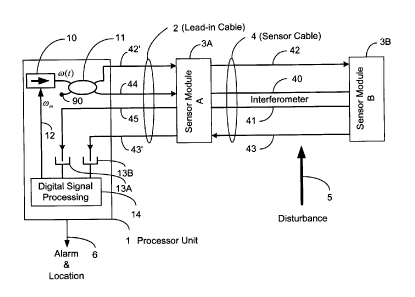
FIG. 1 is a schematic diagram showing an overview of the modules of a stereo
Michelson interferometric fiber optic perimeter security apparatus in
accordance with the
present invention.
8
CA 02780396 2012-06-13
FIG. 2 is a schematic diagram provided for reference to describe the basic
elements of
a Michelson-type interferometer with Faraday Rotational Mirrors as utilized in
the
present invention.
FIG. 3 is a graph on which the amplitude of the Bessel Functions of the First
Kind;
JO(C), J1 (C), and J2(C), are plotted as a function of the argument C along
with the
desired operating point.
FIG. 4 is a schematic diagram showing the modules of FIG. 1 in greater detail.
FIG. 5 is a diagram showing a conceptual illustration of the primary two
Michelson and
the undesired Mach Zehnder interferometers which are inherent to the stereo
Michelson
interferometric fiber optic perimeter apparatus of the present invention.
FIG. 6 is a functional block diagram showing the processing functions
performed by the
digital signal processing module of FIG. 1.
FIG. 7 is a schematic illustration showing the inputs and outputs of the basic
complex
fast Fourier transform (FFT) operation of the digital signal processing module
of FIG. 6.
FIG. 8 is a schematic illustration showing the bridge measurement of the
digital signal
processing module of FIG. 6.
9
CA 02780396 2012-06-13
DETAILED DESCRIPTION OF INVENTION
The basic modules of a stereo Michelson interferometric fiber optic perimeter
security
apparatus in accordance with the present invention are shown in FIG. 1. A
processor
unit 1 is typically housed indoors. The processor unit 1 includes a laser
source 10, a
splitter 11 (illustrated as an interferometric splitter/combiner with a
terminated/unused
port 90), optical detectors 13A and 13B and a digital signal processing module
14.
Lead-in cable 2 connects processor unit 1 to an optical interferometric sensor
module
3A. Lead-in cable 2 comprises optical fiber feeder lines 44 and 42' which
connect laser
source 10 to each of the stereo Michelson interferometers of optical
interferometric
sensor modules 3A and 3B. A fiber optic sensor cable 4 connects sensor 3A to
sensor
3B. Sensor cable 4 comprises fiber optic feeder lines 42 and 43 which send the
light
source input signal to, and return the output response signal from, the
Michelson
interferometer of sensor 3B. In addition, sensor cable 4 includes a fiber
optic sense line
40 and a fiber optic reference line 41 which provide the common arms of the
stereo
(alternately referred to herein as back-to-back) Michelson interferometers
provided by
the sensor modules 3A and 3B. Since the sense and reference lines 40, 41 are
shared
by the two Michelson interferometers they each see the same disturbance but
the
stereo signal responses to the disturbance, produced by them, are distorted
relative to
each other due to the inherent functioning of a Michelson interferometer.
A disturbance 5 caused by an intruder is applied to the sensor cable 4 which
is attached
to a fence (not illustrated) mounted around the perimeter of the area to be
secured (or,
alternatively for a different embodiment could be buried below the surface of
such
perimeter so that a seismic signature is produced in the sensor cable when an
intruder
walks over it). Lead-in cable 2 is insensitive to disturbances. All active
components of
the perimeter security apparatus are in processor unit 1 with only passive
components
outdoors thereby providing a perimeter security apparatus that is immune to
EMI and
RFI.
A characteristic of a Michelson interferometer is that it sees a disturbance
twice. This
manifests as a filter effect on the response of the interferometer and enables
the
CA 02780396 2012-06-13
response to be modeled or represented mathematically by a predetermined
function.
The two Michelson interferometers of sensors 3A and 3B produce a stereo signal
response. As demonstrated by the mathematical analysis set out in the
following, a
disturbance applied to sensor cable 4 produces a complex signal response.
Digital signal processing is used to implement a bridge. One half of the
bridge is formed
by the two sensor response signals, each component of which may be represented
by
the inherent RCF function, alternately referred to as the RCF filter and RCF
filter
function. The other half of the bridge is formed as inferred (i.e.
theoretical) responses
The range associated with each step of the iterative bridge measurement is
referred to
as a range bin. The range bin in which the bridge output is closest to zero is
the range
bin in which the disturbance is located and is referred to herein as the
disturbance
11
CA 02780396 2012-06-13
Frequency domain digital signal processing is used for the bridge measurement
in the
illustrated embodiment. However, it is to be understood that an alternate
embodiment
of the invention might instead use time domain digital signal processing to
implement a
bridge type measurement.
During an intrusion attempt the fiber optic sensor cable 4 is disturbed due to
an impact
to, or motion of, the fence to which it is attached. The two Michelson
interferometers of
sensors 3A and 3B share the same sense and reference fibers 40, 41 but are of
opposite orientations. The single laser source 10 and splitter 11 launch light
in one
direction along the sensor cable as part of the first Michelson interferometer
of sensor
3A and, simultaneously, in the opposite direction as part of the second
Michelson
interferometer of sensor 3B. The sense and reference fibers 40, 41 are
terminated in
Faraday rotational mirrors (FRMs) 30A, 31A and 30B, 31B for each of the two
Michelson interferometers. The use of FRMs in the terminations of the
Michelson
interferometers solves the problem of polarization induced fading that affects
other
interferometers.
The disturbance 5 of the sensor cable 4 caused by an intruder changes the
length of the
sense fiber 40 relative to the reference fiber 41 at the point of the
disturbance 5. This
change in relative length causes the two Michelson interferometers to produce
a wide
band signal frequency response on lead-in cable 2 feeder lines 45 and 43'
which are
connected to the outputs of the Michelson interferometers. Characteristics of
the
resulting two wide band signal frequency responses are used to determine that
a
disturbance 5 caused by an intrusion attempt is in progress and to identify
the location
along the sensor cable 4 where the disturbance/intrusion attempt is occurring.
The frequency (wavelength) of the laser source 10 that drives the Michelson
interferometers of the two sensors 3A, 3B is modulated. Relatively small
optical delay
lines 34A, 34B are strategically located in the sense and reference lines 40,
41 so that
the split modulated laser source signals produce symmetric output signal
responses
that are rich in harmonics on each of the Michelson interferometers. The
output signal
12
CA 02780396 2012-06-13
responses at the modulation frequency, and at twice the modulation frequency,
are
used to measure the complex frequency response associated with the disturbance
using two complex Fast Fourier Transforms (FFT).
s Even though the two Michelson interferometers respond to the same
disturbance the
complex frequency response seen by the two Michelson interferometers differ.
The
difference is described herein as the Range Cosine Filter (RCF) effect. The
location of
the disturbance relative to the FRMs of each of the Michelson interferometers
produces
a unique ROE effect. Digital signal processing is performed on the measured
complex
frequency responses to effect a bridge measurement of the disturbance seen by
each
interferometer and from this the location of the disturbance along the length
of the
sensor cable 4 is determined.
If desired, it is possible to use the same laser source to simultaneously
support a
second set of stereo fiber optic sensor responses, for purposes of redundancy
and
improve fault tolerance, whereby a second sensor cable and second set of
sensor
modules are installed parallel to the first. For such an embodiment, in normal
operation
the signal responses resulting from the two sets of sensor cables and modules
can be
integrated together to enhance the overall sensor performance. Further, when
used on
a fence such dual operation could be used to distinguish between different
types of
disturbances by determining signal response differences generated by, say, a
"cut" and
a "climb". In buried applications it could be used to determine the direction
and speed
of crossing. In any case, if either sensor cable is cut the interferometric
sensors would
continue to operate but with the performance characteristics of a single
sensor cable.
Still further, for other applications such a sensor cable redundancy could be
used to
divide the security perimeter into two independent lengths in order to better
suit the
particular site requirement.
Michelson interferometers with Faraday Rotational Mirror (FRM) terminations
are used
to provide a cost effective means to avoid polarization induced fading. In all
other types
of interferometers such as Sagnac, Mach Zehnder and Michelson with normal
mirror
13
CA 02780396 2012-06-13
termination polarization induced fading is a severe problem that typically is
resolved
through the use of relatively costly polarization controllers or polarization
scramblers. It
can also be solved by use of polarization maintaining fiber in the sensor
cable but such
a solution would add considerably to the cost of implementation.
The single modulated laser source 10 used to drive the stereo Michelson
sensors 3A,
3B advantageously separates the stereo signal responses of the two Michelson
interferometers while minimizing the effect of unwanted responses, to
effectively
suppress or reject those unwanted responses, as detailed more fully in the
following.
The modulation provides what is referred to hereinafter as a "pseudo-
intermediate
frequency (IF)" for each of the complex time domain responses from the stereo
Michelson interferometers. The meaning and reason for choosing to use the term
"pseudo-IF" here draws upon the readily apparent analogies between this
modulation/demodulation structure and those of a conventional heterodyne radio
receiver, as explained more fully below. In a demodulation process performed
by the
digital signal processor 18 the in-phase and quadrature-phase responses from
the two
Michelson interferometers are retrieved. The optical time delay elements 34A,
34B are
symmetrically located in the interferometric sensors 3A, 3B to create
symmetrical
responses, a positive frequency response in one Michelson interferometer and a
negative frequency response in the other. At the same time it suppresses an
undesired
response that is created from an undesired primary Mach Zehnder interferometer
that is
inherent to the design of sensors 3A and 3B in addition to the primary stereo
Michelson
interferometers. As will be appreciated by one skilled in the art, the
resulting phasor
response obtained from the sensor A and B responses (i.e. the combination of
sensor
modules 3A, 3B and sensor cable 4) may, to advantage, be represented by
alternative
complex components to suit particular processing requirements. More
specifically,
rectangular or polar co-ordinates, in either of the time and frequencies
domains, may be
used to represent and process the phasor response of the sensor.
The term "pseudo-IF" used herein refers to the higher frequency signal onto
which the
sensor response signal is superimposed. By way of explanation of the choice of
this
14
CA 02780396 2012-06-13
term, it is arbitrarily chosen for purposes of description and in view of
certain analogies
of the subject sensor response signal to the IF of a conventional heterodyne
receiver
which persons skilled in the art will readily recognize. Here, the information
of interest,
being the response to a disturbance on the sensor cable, is superimposed as
response
modulation on a higher frequency signal and is retrieved by beating that
higher
frequency down to base band. For convenience, that higher frequency signal on
which
the response signal of interest is superimposed is referred to as the "pseudo-
IF".
However, unlike a conventional heterodyne receiver, due to the nature of the
response
modulation process (see the following discussion using Bessel Functions) the
quadrature-phase component is at the first harmonic and the in-phase component
is at
the second harmonic.
Numerous additional multipath interferometers are also inherent to this design
but
responses from such higher order multipath Mach Zehnder and Michelson
interferometers are significantly attenuated by the design and the use of
modulation and
the multiple passes through the various splitter/combiner devices. As will be
readily
understood by one who is skilled in the art, residual responses from even
order
multipath Michelson interferometers produce the same range information as the
primary
Michelson interferometers and residual responses from odd order multipath
Michelson
interferometers, that could add noise to the ranging process, are
substantially
attenuated due the number of splitter/combiners involved and to the very long
optical
path length differences involved and through a selection of a laser source
with a
coherence length that is less than the length of the sensor cable 4.
The analog stereo output signal responses 45, 43' from the opposing Michelson
interferometers of sensors 3A, 3B are detected 13A,13B, low pass filtered 15A,
15B,
converted from analog to digital signals 16A, 16B and then digitally processed
by a field
programmable logic array (FPGA) 17 which applies two complex Fast Fourier
Transform (FFT) routines. Each of the stereo Michelson interferometer
frequency
domain signal responses includes a data sequence associated with the
disturbance 5
that is distorted by an inherent Range Cosine Filter (RCF). This disturbance-
associated
CA 02780396 2012-06-13
data sequence is alternately referred to herein as a sound bite of data
because it is a
1024 point (or as long as the FFT) sample segment of the signal and is,
roughly, in the
audio frequency band or high in the illustrated embodiment. The RCF effect
provides
information as to how the sound bite is distorted in the frequency domain as a
function
of the range of the disturbance to the FRMs of the interferometer in question.
The RCF
effect increases with the frequency content of the disturbance and with the
range to the
FRMs. The present invention exploits the differences in the stereo frequency
responses
of the two Michelson interferometers due to the RCF effect to locate the
disturbance 5
along the length of the sensor cable 4. Although it is common to find in some
textbooks
lo and technical papers a statement that one of the advantages of a
Michelson
interferometer over a Mach Zehnder interferometer is that it is twice as
sensitive. While
this is true it overlooks the RCF effect and hence the two times increase in
sensitivity is
only true for short Michelson sensors or for low frequencies and when the
disturbance is
in proximity to the FRMS.
Next, the stereo complex frequency domain signal produced by the FPGA 17 are
used
to form two arms of a measurement bridge used to determine the location of the
disturbance 5. Unlike the RCFs which are inherent in the design (i.e. in the
arms of
each Michelson interferometer), digital signal processing 18 is used to
establish the
bridge structure and perform the bridge measurement. By digitally creating
inferential
range cosine filters (RCFs) and range sine filters (RSFs) and using them as
two of the
arms of a bridge, with the complex signal produced by the FPGA 17 used for the
other
two arms, the inferentially created arms of the digital side of the bridge can
be adjusted
to balance the bridge and in doing so locate the disturbance 5 along the
length of the
sensor cable 4. The adjustments are performed iteratively until balancing is
effected.
The use of a Wheatstone Bridge to measure resistance is taught in most basic
measurement courses in Electrical Engineering. These courses typically
describe the
advantage of a bridge measurement as being that the balance point is valid
regardless
of the supply voltage. This is true of all types of bridges including radio
frequency
bridges. In the present invention the use of the bridge measurement means that
the
16
CA 02780396 2012-06-13
balance point is not significantly affected by amplitude or phase noise on the
laser
source. This means that one can use a less costly laser source than might be
used in
other types of interferometric sensors.
In order to understand the operation of the present invention it is necessary
to
appreciate the workings of a Michelson interferometer with Faraday Rotational
Mirrors
and the process of using modulation to generate complex responses (which may
be
represented in the frequency or time domain, as desired) to a disturbance
applied to
sense fiber of such Michelson interferometer. In the following a review of
these workings
is undertaken and an analysis of the modulation process from which several
important
equations describing the process result.
A basic Michelson interferometer is illustrated in FIG. 2. A laser source 10
sends a
frequency modulated light signal to a 2x2 splitter/combiner 35 where it splits
(50/50)
onto a sense line 40 and a reference line 41. With the exception of an optical
path
difference (OPD) produced from an optical time delay element 34 the sense line
40 and
the reference line 41, forming the arms of the interferometer, are of equal
optical path
length. The two light signals propagate along the two arms of the
interferometer to
Faraday rotational mirrors (FRMs) 30 and 31 at the ends of the lines 40, 41.
The light is
zo reflected by the mirrors back along the arms of the interferometer
returning to the 2x2
splitter/combiner 35 where they are summed together and exit the 2x2
splitter/combiner
35 to arrive at optical detector 13 which measures the intensity of the
combined
responses.
The interferometric action occurs in the summation process of the 2x2
splitter/combiner
35. When the light signals are "in-phase" they add and when they are "out-of-
phase"
they subtract. This means that the intensity of light measured by the detector
13, in
effect, measures the relative phase of the light returned on sense line 40 to
that
returned on reference line 41.
17
CA 02780396 2012-06-13
The basic interferometric action just described is common to all
interferometers
including Mach Zehnder, Sagnac and Michelson Interferometers. A problem of
"polarization induced fading" can occur in all such interferometers. The
summation
process occurring in the splitter/combiner depends on relative phase and
relative
polarization. Hence for the intensity output of the optical detector to
accurately measure
the relative phase of the two input signals they must have the same
polarization. If the
polarization of the two signals happens to be orthogonal then the output will
be zero
regardless of the phase. A problem is created by the fact that as light
propagates along
the fiber its polarization changes in a somewhat random manner and these
changes
vary with time and temperature. The effects of "polarization induced fading"
can be
minimized through the use of polarization controllers or polarization
scramblers but
these add cost and complexity to the interferometer. In addition it is often
necessary to
briefly interrupt the detection process while the polarization is adjusted.
While perhaps
unlikely, this could make the sensor vulnerable to not detecting a disturbance
caused by
an intruder. The FRMs provide an inexpensive alternative to polarization
controllers or
polarization scramblers for the Michelson interferometer and they allow the
sensor to
operate without interruption.
A person skilled in the art will understand how FRMs work and there are
numerous
papers and articles describing such workings. The end result is that the
Faraday
rotators in front of the mirrors ensure that the light reflected from the FRM
has a
polarization that is 90 degrees from that of the light entering the FRM. This
means that
the light arriving back at the 2x2 splitter/combiner always has the same
polarization as
when it left thereby overcoming the effects of "polarization induced fading".
Sense line 40 and reference line 41 are embedded in a sensor cable 4 which is
affixed
to the fence structure. When the fence fabric is cut by an intruder or when
the fence
fabric is deformed by an intruder climbing on the fence the sensor cable is
flexed and
the length of sense line 40 changes relative to the length of reference line
41 at the
point of the disturbance thereby generating a signal at the output of optical
detector 13.
18
CA 02780396 2012-06-13
This is the basic mechanism whereby a Michelson Interferometer with FRMs
detects
intruders.
In order to use modulation to measure the frequency response at the output of
optical
detector 13 an optical path difference (OPD) 34 is added to sense line 40 by
inserting a
time delay element 34. This insures that when the frequency of the light
source changes
the number of wavelengths in the total path length in sense line 40 plus OPD
34 is
different from that in reference line 41. This generates a pseudo-intermediate
frequency
(pseudo-IF) output at the modulation frequency and at twice the modulation
frequency
that allows one to usefully measure the in-phase and quadrature-phase of the
output of
the optical detector. As will be recognized by persons skilled in the art, it
is necessary
that the light source have a coherence length well in excess of the OPD.
In single mode fiber, light typically propagates at 68.13% the speed of light
in free
space. It is this velocity that determines the time taken to propagate to the
FRMs 30 and
31 and back from the 2x2 splitter/combiner 35. Let us refer to the propagation
time in
sense line 40 plus the OPD 34 as Ts and the time in reference line 41 as TR .
The momentary frequency at the input to splitter/combiner 35 is assumed to be:
Cd(t)= + AO)cos(0)mt)
where wo is the optical carrier frequency of the light, kis the modulation
frequency and
Am is the modulation depth. All frequencies expressed herein are in "radians /
second".
A fundamental characteristic of this classic frequency modulated wave is that
the
frequency deviation em is proportional to the peak amplitude of the modulating
signal,
and is independent of the modulation frequency. The phase angle of the signal
arriving
back at splitter/combiner 35 reflected from FRM 30 on sense line 40 can be
expressed
as:
19
CA 02780396 2012-06-13
r+7.5
(t)= Sw(t')de
and the phase angle of signal arriving back at splitter/combiner 35 reflected
from the
FRM 31 on the reference line 41 can be expressed as;
t+TR
OR (t) = 1(0(0 de
It follows that
Act) f
OS (0= coo(Ts)+¨isin[com (t +Ts)]--sin[Wnit]l
tom
and
r
(t) = (00(R) a- sin[ok (t + TR )1¨sin[conzt]
Vn I
These equations describe the phase of the signals that are summed together in
splitter/combiner 35 as a function of time. The summed signal can be expressed
as;
E(t)= ei[41-1-00)1 eikv+0R(191
where j = jiT (the imaginary operator). The intensity of light at the output
of optical
detector 13 is
In(t) =1E (Or = E(t) E(t)*
where (*) is the complex conjugate operator. It then follows that the
intensity of the light
at the output of optical detector 13 can be expressed as:
In(t)= 2+ 2 cos{ Os (t)-0R(t)
CA 02780396 2012-06-13
Using this equation and the phase terms previously defined along with some
trigonometric identities it follows that
In(t)= 2+ 2 cos[wo (Ts ¨TR)1COS{¨AW Sin{co,n[Ts ¨TR]}COS{COm(t +[Ts +TR])}}
2 2
Aw
¨ 2 sin [wo(Ts ¨TR) jsin{¨wm sin{w. [ Ts ¨2 TR1}COS{W t TS +TR
[
There are two Bessel function expansions on page 361 of the "Handbook of
Mathematical Functions" by Abramowitz and Stegun (being a reference text that
is well
known to, and commonly used by, persons skilled in the art) that are
particularly helpful
in interpreting this equation
9.1.44 cos[ z cos(9) ]= Jo (z)+ 2 Ec-ok .12k(Z)COS[2k
k=1
9.1.45 sin[ z cos(9) 1= 21 (¨ J2k,i (Z)COS[(2 k + 1) 0]
k=0
Equations (9.1.44) and (9.1.45) describe the generating functions of the
associated
series of Bessel Function of the First Kind.
After considerable manipulation of equations and low pass filtering to remove
the higher
harmonics it can be shown that the intensity of light at the output of optical
detector 13
is
In(t)= 2 + 2 Jo [ C]cos[woTA
¨ 4J, [ dcos[ con, + TA sin[cooTA
¨4 J2[C]cos[2 coni(t+T)] cos[cooTA
where the argument of the Bessel Functions is defined as
21
CA 02780396 2012-06-13
C= AC sinf wmT
co,õ L 2 j
and the time delay associated with OPD 34 is T.
J2(C)respectively. All three Bessel Functions share the same argument C.
From the equation for the intensity of light at the output of optical detector
13 it is clear
that the first term involving Jo(C) is at base band, the second term involving
J1(C)isthe
modulation of the harmonic at twice the modulation frequency, 2m
In order to understand the significance of the Bessel functions; Jo(C), J1(C),
.12 (C) and
FIG. 3. There are three important observations to make:
J(C)=J2(C)=O when C=0
J1(C)= J2 (C)= 0.46235 when C=2.630
J 2(C)=¨ 0.46235 when C=-2.630
C=0 when T=0
sign(C)=sign(TA)
TA then quadrature term of the optical phase output depends on the sign of TA
and has
the same amplitude as the in-phase term.
22
CA 02780396 2012-06-13
In the complex time domain the sign of the quadrature-phase component (Q)
defines
the direction of rotation of the time domain phasor. Hence when Tõ is positive
the phasor
rotates in a positive direction and when Tõ is negative the phasor rotates in
a negative
direction. In the complex frequency domain this relates to positive and
negative
frequencies.
One could repeat the same analysis for a Mach Zehnder interferometer. Similar
to the
Michelson case, it can be shown there are zero first and second harmonic term
outputs
lo if one selects C=0 which would relate to a zero OPD (Tõ =0) . In other
words a Mach
Zehnder interferometer with zero OPD does not produce any first or second
harmonics.
When the sensor cable is disturbed, sense line 40 changes in length relative
to
reference line 41 at the location of the disturbance 5. This relative change
in length
occurs over a short length (a few meters) of the sensor cable. In the complex
time
domain the relative change in length, d(t) , creates a complex time domain
response of
r(t)= I r(t)+ iQr(t)
where j=../ , /r(t)=C cos( 1 d(t)) and Q,.(t). c sin( 1 d(t))
2 Al) 2 a
the intensity of the light, C is not altered appreciably by the disturbance
the intensity of
the light but the phase of the light is changed in proportionality to
d(t)divided by the
wavelength of the light A).
In general r(r)is cyclical in nature and it tends to decay in magnitude with
time as the
sense and reference lines return to their static position following the
disturbance. The
peak change is typically many wavelengths (say 20 to 30 wavelengths) in
amplitude. It
is a very random function since it depends on the positioning of the fibers in
the cable,
the amplitude of the disturbance of and the coupling of the disturbance to the
fibers. In
practice no two disturbances will be the same.
23
CA 02780396 2012-06-13
Taking the Fourier Transform of the complex time domain function r(t)the
complex
frequency domain response is
R(6)= Er(t) dt
In the complex frequency domain a typical disturbance has a broad spectrum of
frequency components ranging from 10 kHz to 700 kHz. Complex frequency
response,
R(co), describes the disturbance 5 at the point of the disturbance. Since one
does not
measure the response at the point of the disturbance, R(co)may seem somewhat
academic but it is important since it forms the common point of reference
between the
two Michelson responses.
In the Michelson interferometer the disturbance affects the light first as it
propagates
towards the FRMs and then again as it propagates back from the FRMs. If one
selects
the time that the light reaches the FRMs as the time point of reference, the
first
disturbance occurs T e seconds before the light arrives at the FRMs and the
second
disturbance occurs Te seconds after the light arrives at the FRMs. Hence in
the
complex frequency domain the measured effect of the disturbance can be
expressed
as:
Re(co)=1eJ + R(0)) =2 coskoT1 R(co)=2cos(--a)t)R(co)
where v is the velocity of propagation in the fiber lines. The range cosine
filter (RCF)
defined herein as:
RCF(w1)=2 cos(---a)t)
distorts the true frequency response R(o) as shown by
Re (0= RCF(cot ) R(m)
and the distortion depends upon the distance between the disturbance 5 and
FRMs 30
and 31 defined as 1. The RCF only affects the amplitude of the frequency
components
and not the phase of these components.
24
CA 02780396 2012-06-13
The stereo fiber optic sensors 3A, 36 and sensor cable 4 of the illustrated
embodiment,
illustrated in FIG. 4, are described in the following in terms of three
primary
interferometers viz. Michelson A (formed by sensor A), Michelson B (formed by
sensor
B) and an inherent Mach Zehnder. The forgoing analysis provides the basis for
why the
Michelson A interferometer produces a positive response in the complex
frequency
domain, the Michelson B interferometer produces a negative response in the
complex
frequency domain and the Mach Zehnder interferometer's outputs at the first
and
second harmonics are suppressed. It also defined the RCF effects relating to
the
Michelson interferometers.
In FIG.1 and FIG.4 several splitter/combiner ports are not used. These unused
ports are
fitted with reflection-less terminations denoted by a "dot" on the device
lead.
In FIG. 4 laser source 10 is modulated at a) radians per second by FPGA 17
over line
12 about a carrier frequency of cao radians per second. The modulated output
of laser
10 is split 50:50 in splitter/combiner 11 to be sent to identical
interferometric sensors 3A
and 36, of which the A and B notation refers to Michelson interferometers A
and 13,
respectively. Interferometric splitter/combiner 35A associated with Michelson
A
interferometer is contained in sensor 3A and splitter/combiner 356 associated
with
Michelson B interferometer is contained in sensor 36. Likewise, time delay
element 34A
associated with Michelson A interferometer is contained in sensor 3A and time
delay
element 34B associated with Michelson B interferometer is contained in sensor
36.
Time delay elements 34A and 346 create OPDs of equal length. Time delay
element
34A adds to sense line 40 and time delay element 34B adds to reference line
41.
In the illustrated embodiment an OPD of 5 meters is used in order to ensure
that the
OPD relating to the inherent undesired Mach Zehnder interferometer 52 is
nominally of
zero length. As will be recognized by persons skilled in the art, in practice
the relative
length of the fibers 40 and 41 in cable 4 will vary over the wide range of
temperatures
that the sensor cable 4 may be subjected to and, in turn, it is difficult to
realize a perfect
zero OPD. Therefore, the OPDs produced by the time delay elements 34A, 346
need
CA 02780396 2012-06-13
to be significantly longer - about an order of magnitude greater, than the
worst case
variation in the Mach Zehnder OPD to ensure adequate suppression of the Mach
Zehnder response.
Splitter/combiner 32A splits the signal arriving on sense line 40 equally
(50:50) between
FRM 30A and splitter/combiner 35B. Likewise splitter/combiner 33A splits the
signal
arriving on reference line 41 equally (50:50) between FRM 31A and
splitter/combiner
35B. Splitter/combiner 32B splits the signal arriving on sense line 40 equally
(50:50)
between FRM 30B and splitter/combiner 35A. Likewise splitter/combiner 33A
splits the
lo signal arriving on reference line 41 equally (50:50) between FRM 31B and
splitter/combiner 35k Throughout, unused/terminated inputs and outputs of the
splitter/combiner components are identified by reference numeral 90. Feeder
lines 42
and 43 carry the light signals to and from sensor 3B and processor unit 1. The
feeder
lines 42, 43 simply pass through sensor 3A for convenience.
Sensor cable 4 comprises four fibers viz, feeder lines 42, 43, sense line 40
and
reference line 41. In practice, there may well be additional fibers included
in sensor
cable 4 for other purposes but only these four fibers are used by the stereo
sensors 3A,
3B.
Lead-in cable 2 similarly comprises four fibers viz, feeder lines 42 and 43,
carrying input
and output signals, respectively, to and from sensor 38 and feeder lines 44
and 45
carrying input and output signals, respectively, to and from sensor 3A.
Because lead-in
cable 2 does not include sense line 40 or reference line 41 it is not
sensitive to motion.
The response from Michelson A interferometer arrives at optical detector 13A
on feeder
line 45. The light being transmitted into Michelson A interferometer is sent
from
splitter/combiner 11 in processor 1 to splitter/combiner 35A in sensor 3A on
feeder line
44. The response from Michelson B interferometer arrives at optical detector
13B on
feeder line 43'. The light being transmitted into Michelson B interferometer
is sent from
26
CA 02780396 2012-06-13
splitter/combiner 11 in processor 1 to splitter/combiner 35B in sensor 3B on
feeder line
42.
While not shown in FIG.4 optical isolators are connected in front of optical
detectors
13A and 13B to prevent reflections from the optical detectors from re-entering
the
interferometers. Likewise laser source 11 must include an optical isolator to
prevent
reflections from the laser source from re-entering the interferometers.
The outputs of optical detectors 13A and 13B are passed through analog low
pass
lo filters 15A, 15B to remove the third and higher harmonics before the
signals are applied
to analog to digital converters (ADCs) 16A and 16B. The digital signals
produced by
ADCs 16A and 16B are passed to a field programmable logic array (FPGA) 17
where
the high speed digital signal processing (DSP) is performed. In addition,
modulation
frequency, co,,,, is generated by FPGA 17 and transmitted on line 12 to laser
source 10.
Digital lines connect FPGA 17 to a computer (PC) 18 where slower speed DSP is
performed. To further reduce the cost of the perimeter security apparatus the
signal
processing performed by PC 18 could be implemented in an embedded
microprocessor
inside FPGA 17 thereby avoiding the cost of PC 18.
In the end, disturbance 5 applied to the sensor cable 4 is detected and
located and
reported as an alarm with location coordinates as an output 6 of PC 18.
The three primary interferometers that share sense line 40 and reference line
41 are
illustrated in FIG. 5. While shown as three separate interferometers in FIG. 5
it will be
understood by the skilled reader that they are all inherently present in the
stereo fiber
optic sensors 3A, 3B with sense cable 4 as shown in FIG. 4. They are
illustrated
separately in FIG. 5 simply as a convenient means of explaining the operation
of the
stereo fiber optic sensors 3A, 3B and sense cable 4.
27
CA 02780396 2012-06-13
Referring to FIG. 5, Michelson A interferometer 50 includes splitter/combiner
35A, time
delay element 34A, sense line 40, reference line 41, FRM 30A and FRM 31A.
Michelson B interferometer 51 includes splitter/combiner 35B, time delay
element 34B,
sense line 40, reference line 41, FRM 30B and FRM 31B. The Mach Zehnder
interferometer 52 shown in FIG. 5 includes; splitter/combiner 35A, OPD 34A,
sense line
40, reference line 41, OPD 34B and splitter combiner 35B. Splitter/combiners
32A, 32B
and 33A, 32B have been omitted to explain the operation of the
interferometers. They
do not inhibit the operation of Michelson A or B interferometers, or Mach
Zehnder
interferometer, but they do add attenuation of the optical signals.
1.0
From FIG. 5 the back-to-back nature of the Michelson A and B interferometers,
50 and
51, is apparent. Each of the Michelson interferometers is similar to the basic
Michelson
interferometer shown in FIG. 2 and functions as previously described. With
time delay
element 34A in sense line 40 the Michelson A interferometer 50 produces a
positive
response in the complex frequency domain. With the time delay element 34B in
reference line 41 the Michelson B interferometer 51 produces a negative
response in
the complex frequency domain.
Because the OPDs created by time delay elements 34A, 34B are the same length
there
is effectively zero OPD in the Mach Zehnder interferometer 52. As described
previously
having a zero OPD means that the first and second harmonic response signals
that
would otherwise be produced by the inherent Mach Zehnder interferometer 52 are
suppressed leaving only the Michelson A and B first and second harmonic signal
responses.
From FIG. 4 one can envisage more than the three primary interferometers.
Multipath
interferometers are created when one considers multiple reflections between
FRM 30A
and FRM 30B interfering the normal operation of the primary interferometers.
Likewise
multipath interferometers are created when one considers multiple reflections
between
FRM 31A and FRM 31B interfering the normal operation of the primary
interferometers.
In addition the multiple reflections between FRM 30A and FRM 30B can interfere
with
28
CA 02780396 2012-06-13
the multiple reflections between FRM 31A and FRM 31B. It is important that the
responses from these multipath interferometers be relatively small compared to
those of
the desired primary Michelson interferometers 50 and 51.
Splitter/combiners 32A, 32B, 33A and 33B attenuate the optical signals passing
through
them by 3dB for each pass. This means that for Michelson A and B
interferometers 50
and 51 the signal is down by 12 dB. For the Mach Zehnder interferometer 52 it
is down
by 6 dB. This means that the null provided at the near zero OPD for the Mach
Zehnder
interferometer 52 must overcome 6 dB and, preferably, at least another 12 dB.
It is
anticipated that there will be some mismatch between the length of the sense
and
reference lines 40 and 41over time and temperature. As indicated above, the
time delay
elements 34A, 34B must be about an order of magnitude longer than the largest
difference between 40 and 41 to achieve the desired suppression of the Mach
Zehnder
response.
There are multipath Mach Zehnder interferometers. These are attenuated by
splitter/combiners 32A, 32B, 33A and 33B and they experience the same zero OPD
suppression as the primary Mach Zehnder and are of little concern.
Responses from higher order multipath Michelson interferometers are also
attenuated
by splitter/combiners 32A, 32B, 33A and 33B. As indicated above, the residual
responses from even order multipath Michelson interferometers produce the same
range information as the primary Michelson interferometers, and the residual
responses
from odd order multipath Michelson interferometers that could add noise to the
ranging
process are substantially attenuated due to the very long optical path length
differences
involved and through the selection of a laser source with a coherence length
that is less
than the length of the sensor cable.
Disturbance 5 affects all three primary interferometers. In the case of
Michelson A
interferometer 50 disturbance 5 is P meters from FRMs 30A and 31A and L-t
meters
from splitter/combiner 35A. In the case of Michelson B interferometer 51
disturbance 5
29
CA 02780396 2012-06-13
is L-t. meters from FRMs 30B and 31B and t meters from splitter/combiner 35B.
The
sensor cable 4 is L meters long.
The objective of the DSP 18 is to determine length which defines the location
of
disturbance 5 along the length of sensor cable 4. The key to achieving this
objective is
in recognizing that Michelson interferometers 50 and 51 respond to the same
disturbance and that the measured complex frequency domain responses from the
Michelson A interferometer 50 is RCF[cot]R(co) and from Michelson B
interferometer 51
is RCF[co(L-OJR(co).
1.0
While the present invention can be adapted to address numerous applications
the
specific embodiment described herein is particularly tailored to the outdoor
perimeter
security requirements associated with detecting intruders who attempt to cut
through, or
climb over, a chain link fence. The following design parameters are optimized
for this
specific application. A standard laser wavelength of 1310 nanometers with a
coherence
length in the order of 100 meters is selected. A modulation frequency of 2 MHz
(
tom =27t fõ,)and a digitization rate of 12 MHz are used. This is designed to
accommodate the harmonic at twice the modulation frequency (4 MHz) and the
response modulation carried on this harmonic. Anti-aliasing analog low pass
filters 13A
and 13B should have a corner frequency of approximately 5 MHz. The 12 MHz
sample
rate means that the outputs of ADCs 16A and 16B are updated every 83
nanoseconds.
The digital signal processing described herein is applied to the data stream
generated
by ADCs 16A and 16B .
The digital signal processing aspects of the present invention are illustrated
in FIG.6.
For purposes of explanation, it is convenient to use analog symbols to
describe the DSP
operation. The first digital processing step is to add a digital delay line to
the responses
from Michelson A interferometer 50. The purpose of this digital delay is to
effectively
match the analog delay in receiving the response for Michelson interferometer
51. In
particular an integer number of sample delay periods (a multiple of the 83
nanosecond
CA 02780396 2012-06-13
sample period) is selected to match the propagation time in feeder line 43
that brings
the Michelson B interferometer 51 response back to sensor 3B.
The Michelson A interferometer quadrature-phase (QA) response is derived by
performing mixing operation 60 of the optical detector output response with
the
modulation frequency, cen , as provided by FPGA 17 on line 12 and low pass
filtering the
output with a corner frequency of approximately 1.4 MHz to remove the upper
cross
products in digital low pass filter 66. Low pass filter 66 is also used to
decimate the
processing rate from 12 MHz to 1 MHz.
The Michelson B interferometer quadrature-phase (QB) response is derived by
performing mixing operation 61 of the optical detector output response with
the
modulation frequency, aim, as provided by FPGA 17 on line12 and low pass
filtering the
output with a corner frequency of approximately 1.4 MHz to remove the upper
cross
products in digital low pass filter 65. Low pass filter 65 is also used to
decimate the
processing rate from 12 MHz to 1 MHz.
The Michelson A interferometer in-phase (IA) response is derived by performing
mixing
operation 62 of the optical detector output response with twice the modulation
frequency, 20Jõõ as provided by FPGA 17 low pass filtering the output with a
corner
frequency of approximately 1.4 MHz to remove the upper cross products in
digital low
pass filter 64. Low pass filter 64 is also used to decimate the processing
rate from 12
MHz to 1 MHz.
The Michelson B interferometer in-phase (119 response is derived by performing
mixing
operation 63 of the optical detector output response with twice the modulation
frequency, 20Jn, as provided by FPGA 17 and low pass filtering the output with
a corner
frequency of approximately 1.4 MHz to remove the upper cross products in
digital low
pass filter 67. Low pass filter 67 is also used to decimate the processing
rate from 12
31
i
CA 02780396 2012-06-13
MHz to 1 MHz. Inverter 69 is included in the quadrature response to invert the
sign of
the complex frequency response from Michelson B interferometer.
The complex time response for Michelson A interferometer is passed to complex
FFT
70A and the complex time response for Michelson B interferometer is passed to
complex FFT 70B.
The operation of the complex FFT process performed by each complex FFT 70A,
70B is
illustrated in FIG.7. A radix-2 complex FFT is used for maximum computational
lo efficiency. In the specific illustrated embodiment of the invention a
1024 point complex
FFT is used (i.e. H =1024). With a 1 MHz input rate the sound bite processed
by the
complex FFT is 1.024 milliseconds long. Since it is a complex FFT the Nyquist
frequency associated with the FFT is 1 MHz which is adequate for the
anticipated 10
kHz to 700 kHz response spectrum. There are 1024 output frequency bins spaced
apart
at 976 Hz.
For notational purposes the sound bites are identified by the subscript "K'.
This
subscript is incremented every 1.024 milliseconds. The individual time and
frequency
samples associated with each complex FFT operation are denoted by the
subscript "h"
where h=0,1,2õH ¨1.
As shown in FIG. 7 the H real and imaginary input variables are labeled as the
conventional / and ()while the real and imaginary outputs of the complex FFT
are
labeled a and b. The H frequency bins describe frequencies from DC tofNyqutst
= The
Nyquist frequency, Livquist, is determined by the sampling rate. Complex FFTs
with real
and imaginary inputs have H inputs and H outputs unlike FFTs that have only
real
inputs and have only H/2 frequency outputs.
Having delayed the Michelson A interferometer input to arrive at the same time
as the
Michelson B interferometer the two complex frequency outputs are of exactly
the same
32
CA 02780396 2012-06-13
disturbance but with the responses distorted by the two inherent Range Cosine
Filters
as RCF[cot]R(co) and RCF[co(L-0]R(M.
The digital signal processing performed for a bridge measurement of the
location of the
disturbance is illustrated in FIG. 8. The left hand side of the bridge is
optical in nature
and it is inherent to the back-to-back Michelson interferometers. The top left
branch 80
of the bridge represents the measured output of the Michelson A
interferometer. The
lower branch 81 the bridge represents the measured output of the Michelson B
interferometer. The RCF is inherent in the measured outputs and the filter
functions
ic shown in 80 and 81 are included only as means of explaining the
operation of the
bridge.
The complex frequency components of these measurements can be interpreted as
aA(K+h) bA(K+h) = RCF[C0h ij [a Ki_h flic+1,1 h=
0,1,...,H ¨1
aB(K+h)+ jbAK,h)=RCFkoh(L¨)] [4K+h+ il3K+11] h =0,1,...,H ¨1
where [aK+h+./flki-h] h=0,1,...,H-1 are the complex frequency components
relating to
the disturbance R(co). The complex frequency domain response at the point of
the
disturbance, R(w)provides a common point of reference. In the above equations,
R(),
is represented by the H complex variables [alc+h +./fix+h] h=0,1,...,H ¨1
which would
be the complex frequency component outputs of a complex FFT had one been able
to
capture the response data at the point of the disturbance and perform a
similar complex
FFT on said data. This describes the inherent RFC responses 80 and 81 from the
two
Michelson interferometers.
The right hand side of the bridge is implemented digitally. There are two
parts to the
right hand side of the bridge; one based on inferential RCF computations and
the other
on inferential RSF computations. The bridge configuration and measurements
provide
the mechanism by which the perimeter security apparatus locates the
disturbance 5 on
the sensor cable 4. By digital signal processing, different bridge arms are
configured to
include specific RCFs for each of a number of pre-determined range bins and
each
such configuration is tested to determine whether the disturbance is in that
particular
33
CA 02780396 2012-06-13
range bin. This is determined when a particular set of bridge arms balance the
bridge
because such state of balance means that the disturbance is located in that
particular
range bin.
The length of the sensor cable 4 extended along the perimeter is partitioned
into a
predetermined number (N) of range bins. Thus, each range bin of the
predetermined
number of range bins corresponds to the distance along the length of the
sensor cable
of that range bin, with the end of the Nth range bin corresponding to the end
of the
sensor cable. The range bins are denoted by the subscript "n" where n=0,1,2õN-
1.
The number of range bins selected for use will depend on the length of sensor
cable 4
and the application of the sensor apparatus. A typical range bin length is 20
meters.
Hence, for a sensor cable 4 that is 2 km long, with 20 meter long range bins
the number
of range bins used for the digital bridge processing is 100 i.e.: N=100. The
range (i.e.:
distance) along the cable to each range bin is denoted by 7õ .
In classical radar, range is the line of sight distance from the transceiver
which together
with azimuth determines location. In this case the azimuth measure is replaced
by the
knowledge of where the sensor cable is installed and range is the linear
distance along
the sensor cable as it follows the perimeter of the site around corners and up
and down
hills. With this modified definition of range the concept of range bins has a
similar
meaning as they do in classical radar. In other words the distance along the
sensor
cable is measured in discrete elements called range bins. Since the
computational
burden on the signal processor increases significantly with the number of
range bins
one typically utilizes relatively large range bins such as the 20 meter range
bin length in
the preferred embodiment.
The first step in implementing the bridge measurement is to compute the
inferential
cosine parameters:
aCAK,õ,õ+ j bCAK.õ, = RCF[coh(L¨ 7)] [aAK,h+ j bkch] 82
34
CA 02780396 2012-06-13
and
aCB Kjoõ, + j bCBK,h,,,= RCFkoh rn] [aB 1 ch + j bB K ,h] 83
for h=0,1õH ¨land n=0,1õN-1. The "C' in the parameter name relates to the
multiplication by the cosine function and the "S" in the parameter name
relates to the
multiplication by the sine function. The length 7 is the distance from range
bin "n" to
FRM 30A and 31A.
Subtracting one result from the other in adder 86 and after some manipulation
it follows
that the "bridge sine function" is
S(õh),õ = (aCA(K,h),õ¨ aCB(K+0,n)+ j (bCA(K4.0,¨ bCB(K +0,n) = 'Ph sin av (yõ
¨0
[
where Th= 2sin[--1c L][ach + j filch]
V
A range sine filter (RCF) is defined as
RSF(o)t)=2 sin(PP)
v
and it is used to compute the inferential sine parameters:
aSAK A, + j bSAch, = RSF[coh(L¨ yn)] [aAlch+ j bAK A] 84
and
aSBK,h,+ j bSI3(K+h),n = RSFfroh yn] [aB 1 ch + j bBK,h1 85
for h=0,1õH ¨land n=0,1õN ¨1 .
,
CA 02780396 2012-06-13
Adding one result to the other in adder 87 and after some manipulation it
follows that
"bridge cosine function" is
C Kh,n --= (aSAK,h,õ +aS/3,,h,õ)+ j(bSAK +bSAK+0,n)=1Ph cos a'h (rn t)
,
Based on the bridge sine and cosine functions the "bridge tangent function" is
defined
as
TAN K õ SK,,, (aCAK h aCB, ch,õ) + (bCAK,h,õ - bCB K'h) = tan[oa
(y. -0]
. ='= ' '
" C chm (aSAKAõ+ aSBK.õ,õ)+ j (bSAK + bSBK.h,)
While the RCF and RSF filters change the amplitude of the various frequency
components they do not change the phase angle of the components hence the
phase
1.0 angles of the numerator equals that of the denominator. This enables
one to simplify the
computation
aCS K h n+bCSK nn
TAN K An= c _____ = tan --(rn-e)]
where
aCSKAn =(aCkch,n ¨ aCB K,h,õ)(aSAK,h,n aSBK,h,n)
bCSKhR = (bCAK,h.õ bCBK,h,n)(bSAK,hm bSBK An)
and
MS K,h,n= max{ LaSAKhfl + aSBK,h,õ)2 (bSAK,h,õ bASBK,h,n )2 I AlSnlin
for h=0,1õH¨land n=0,1õN-1.
A minimum bound MS,,õõ is imposed to avoid a division by zero. This does not
affect the
bridge measurement since when balanced the denominator term MS(K+h),n is
maximized.
36
CA 02780396 2012-06-13
The function TANK,,,, describes the tangent of the angle --Aa) (71õ for
each of the H
frequency outputs of the FFT and for each of the N range bins in terms of the
H outputs
of the complex FFT.
When the inferred range bin xi is close to the location of the disturbance, ,
the angle
¨t(yõ ¨ e) becomes small for all frequencies and the TANK,,,, function can be
approximated by the angle.
In order to locate the nearest range bin to the location of the disturbance
the parameter
NSK,õ is defined as
H ¨I
NS K,, = El aCSKhfl bCS K ,h,õ1
h=0
The disturbance is located in range bin nx where NSK,,,, is a minimum.
From this computation one knows where the disturbance is along the sensor
cable to
the nearest range bin. In many cases it is desirable to determine the range of
the
disturbance more accurately than to the nearest range bin. While one could do
so by
increasing the number of range bins and hence reducing the length of each
range bin
this comes at a significant computational burden. Even still the range
accuracy is limited
to the range bin size in this approach.
A more efficient means of determining the precise range associated with a
disturbance
involves the use of the TANK,,,, function and linear interpolation. The TAN K
,h,n function is
computed for range bins nx-2,nx-1, nx, nx+1 and nx-i-2 and the precise
location where
the TANK,,,, function goes to zero is determined using linear interpolation of
the data
37
CA 02780396 2012-06-13
about range bin nx . At this point the bridge is balanced and the disturbance
has been
precisely located.
In summary the inferential side of the bridge scans through all range bins to
find the
range bins that bring the bridge near to its balance point. The precise
location of the
disturbance is then determined using linear interpolation of the TAN K,h,n
data to find the
exact location where the bridge is balanced.
The denominator term MSch,h is a measure of the magnitude of the frequency
components for each of the H frequency bins at range bin nx. Once located to
the
nearest range bin, nx, it is useful to compute the weighted average energy
over all H
frequency bins.
H-I
EKja .EwhmsK,h,õõ
/7=-0
where weighting parameters wh h=0,1,....,H¨lare selected to roughly match
filter the
expected frequency response of the anticipated disturbance. While only one set
of
weighting function are presented in this description of the stereo Michelson
fiber optic
sensor it is anticipated that in some applications two or more weighting
functions may
be used to optimize the sensor performance. For example one set of weighting
functions may be used to filter the anticipated lower frequency components
associated
with a person climbing on a fence while another set of weighting functions may
be used
to filter the anticipated higher frequency components associated with a person
attempting to cut through a fence. Different weighting functions will be used
when the
sensor is buried in the ground and one is detecting walking or running
intruders.
The weighted average energy, Ef 0,õ is used to update a response range bin
high pass
filter. For range bin "me where the intruder has been located the range bin
high pass
filter equation is
38
CA 02780396 2012-06-13
= r{ - E(K¨I),nx
and for all other range bins
RK,n= F RK¨I,n
This represents a digital single pole low pass filter for each range bin
response that is
updated for every sound bite when Kis incremented. The filter constant F is
selected
1.0 to match the nature of the disturbance. For the detection of a person
cutting the fence
F is selected to accommodate a shorter duration disturbance than would be
selected for
the detection of a person climbing on a fence. Likewise different filter
constant F would
be used when the sensor cable is buried in the ground.
For a fence disturbance application the high pass filter should have a time
constant of
approximately 50 milliseconds. With the filter updated every millisecond a
filter constant
of F=0.0198 is appropriate.
The cycle of data collection, computation of the complex FFT and execution of
the
bridge measurement is repeated for every sound bite of data as window counter
Kis
incremented. In practice it is anticipated that K increments approximately
once every
millisecond.
Each time that the range buffer is updated the energy in each range bin buffer
is
compared to a threshold for that particular range bin. When the energy exceeds
the
threshold an "Event" is declared in the particular range bin. If desired the
precise
disturbance location derived with every bridge measurement and be averaged for
each
range bin to provide a more precise Event location.
39
CA 02780396 2012-06-13
As with many fence disturbance sensors an "Alarm" is only declared when there
have
been P Events detected at, or near, the same location within a given time
window.
Typically P is selected to be 2, 3, 4, or 5. A typical time window for the
Event count is 3
to 8 minutes.
While the embodiment used to describe the present invention is optimized for a
fence
mounted outdoor perimeter security apparatus, the various parameters described
herein
for the illustrated embodiment, such as laser wavelength, laser coherence
length,
modulation frequency, sampling rate, size of complex FFTs, number of range
bins and
1.0 the filter constants, can be adjusted appropriately by a person skilled
in the art to
accommodate many other applications.
Applications in which the sensor cable is buried is just one other example.
The
protection of oil and gas pipelines is another application. A further example
of an
15 application is for securing fiber optic communications lines. It is well
known that data
can be extracted from fiber optic cables buy a number of nefarious means. This
usually
requires some manipulation of the cable. By including stereo fiber optic
sensors
according to the present invention on the same cable this can be prevented.
The
present invention provides a very cost effective means of detecting and
locating such
20 attempts to steal valuable data.
The securing of data lines has an application in outdoor security. In many
high security
sites it is necessary to utilize a number of sensor technologies on the
perimeter as well
as video cameras for assessment purposes. These additional devices require the
use of
25 a secure data network around the perimeter. Including the stereo fiber
optic sensors
described herein on the data network cable, with data network fibers in the
sensor
cable, provides a cost effective solution to this requirement.
In the case of perimeter security it may be desirable in high security
applications to
30 install redundant sensors. Having parallel but spaced apart stereo fiber
optic sensors
CA 02780396 2012-06-13
provides redundant operation as well as improved performance through
integration of
sensor data.
The invention has been described in a specific embodiment that should be
considered
as illustrative only and not limiting of the invention. Reference should be
made to the
claims to determine the scope of the invention.
41