Note: Descriptions are shown in the official language in which they were submitted.
CA 02780610 2012 05 11
WO 2011/058322 PCT/GB2010/002087
1
IMPROVEMENTS IN DISTRIBUTED FIBRE OPTIC SENSING
The present invention relates to fibre optic distributed sensing, and
especially to fibre
optic distributed acoustic sensing and to method and apparatus for improving
the
functionality of distributed fibre optic sensors.
Various sensors utilizing optical fibres are known. Many such sensors rely on
fibre
optic point sensors or discrete reflection sites such as fibre Bragg gratings
or the like
being arranged along the length of an optical fibre. The returns from the
discrete point
sensors or reflection sites can be analysed to provide an indication of the
temperature,
strain and/or vibration in the vicinity of the discrete sensors or reflection
sites.
Such sensors using discrete reflection sites or fibre optic point sensors
require the
optical fibre including the sensor portions to be specially fabricated.
Further the
distribution of the sensors within the optical fibre is fixed.
Fully distributed fibre optic sensors are also known in which the intrinsic
scattering from
a continuous length of optical fibre is used. Such sensors allow use of
standard fibre
optic cable without deliberately introduced reflection sites such fibre Bragg
gratings or
the like. The entire optical fibre from which a backscatter signal can be
detected can
be used as part of the sensor. Time division techniques are typically used to
divide the
signal returns into a number of time bins, with the returns in each time bin
corresponding to a different portion of the optical fibre. Such fibre optic
sensors are
referred to as distributed fibre optic sensors as the sensor options are fully
distributed
throughout the entire optical fibre. As used in this specification the term
distributed
fibre optic sensor will be taken to mean a sensor in which the optical fibre
itself
constitutes the sensor and which does not rely on the presence of specific
point
sensors or deliberately introduced reflection or interference sites, that is
an intrinsic
fibre optic sensor.
Various types of distributed fibre optic sensor are known and have been
proposed for
use in various applications.
US patent No. 5,194,847 describes a distributed acoustic fibre optic sensor
for intrusion
sensing. A continuous optical fibre without any point sensors or specific
reflection sites
is used. Coherent light is launched into the optical fibre and any light which
is Rayleigh
CA 02780610 2012 05 11
WO 2011/058322 PCT/GB2010/002087
2
backscattered within the optical fibre is detected and analysed. A change in
the
backscattered light in a time bin is indicative of an acoustic or pressure
wave incident
on the relevant portion of optical fibre. In this way acoustic disturbances at
any portion
of the fibre can be detected.
GB patent application publication No. 2,442,745 describes a distributed
acoustic fibre
optic sensor system wherein acoustic vibrations are sensed by launching a
plurality of
groups of pulse modulated electromagnetic waves into a standard optical fibre.
The
frequency of one pulse within a group differs from the frequency of another
pulse in the
group. The Rayleigh backscattering of light from intrinsic reflection sites
within the fibre
is sampled and demodulated at the frequency difference between the pulses in a
group.
Distributed fibre optic sensing therefore provides useful and convenient
sensing
solutions that can monitor long lengths of optical fibre with good spatial
resolution. For
instance a distributed fibre optic acoustic sensor, for instance as may be
used for
monitoring a pipeline, can be implement with sensing portions 10m long in up
to 40km
or more of optical fibre.
It is an aim of the present invention to provide a distributed fibre optic
sensing system
with increased flexibility and/or utility.
Thus according to the present invention there is provided a distributed fibre
optic
sensor comprising an optical source configured to interrogate an optical fibre
with
optical radiation, a detector configured to detect optical radiation back-
scattered from
within the fibre and a processor configured to process the detected back-
scatter
radiation to provide a plurality of longitudinal sensing portions of fibre
wherein the
optical source and processor are adapted to provide a first spatial resolution
and at
least a second, different spatial resolution.
The distributed fibre optic sensor of the present invention transmits optical
radiation
into a sensing optical fibre, detects radiation back-scattered from within the
fibre and
processes the radiation so as to define and to generate measurement signals
from
each of a plurality of longitudinal sensing portions of the fibre as is
conventional in
distributed fibre optic sensing. Each longitudinal sensing portion of fibre
can therefore
be considered as a separate sensor or data channel and the optical fibre can
CA 02780610 2012-05-11
WO 2011/058322 PCT/GB2010/002087
3
effectively be seen as a series of independent sensors (which may or may not
be
contiguous). However, in embodiments of the present invention a sensor is
afforded
which exhibits a first spatial resolution and/or a second different spatial
resolution. In
other words the size of the longitudinal sensing portions of the fibre are
configurable
such that each sensing portion of fibre may be either a first length or at
least a second
length, different to the first. Different embodiments of the invention control
the variation
in spatial resolution in different ways. Techniques such as temporal
variation, adaptive
variation in response to a detected event, simultaneous provision of multiple
reolutions,
eg by wavelength multiplexing are described below in more detail. In
conventional
distributed fibre optic sensing the spatial resolution, i.e. the basic length
of the sensing
portions of fibre, is fixed.
The optical source may be arranged to interrogate the optical fibre with one
or more
pulses of optical radiation. Each pulse effectively illuminates a section of
the fibre and
back-scatter from that section of the fibre can be detected by the detector.
In certain
embodiments the lengths of the longitudinal sensing portions of the fibre are
determined by the duration, or width of the optical pulse or pulses being used
to
interrogate the fibre. In essence scattering caused by light in the middle of
the pulse
will reach the detector at the same time as light from other parts of the
fibre illuminated
by earlier or later bits of the pulse.
Thus the optical source may be configured to interrogate the optical fibre
with pulses of
optical radiation of a first duration and also to interrogate the optical
fibre with pulses of
optical radiation of second duration. By changing the duration of the pulse of
optical
radiation the spatial resolution of the sensor, i.e. the length of the sensing
portions of
fibre, can be varied.
In a distributed acoustic sensor such as described in GB2,442,745 pairs of
pulses are
used for each interrogation, with a frequency difference between each pulse in
a pair.
In certain distributed sensing arrangements then, pairs of pulses are used,
and the
relative phases of backscattered light from each one of a pair of pulses can
be used to
provide sensed data. In such embodiments the length of the longitudinal
sensing
portions of the fibre is related to the separation between pulses in an
interrogating pair.
Therefore in embodiments of the invention the optical source is configured to
interrogate the optical fibre with pairs of pulses of optical radiation having
a defined
CA 02780610 2012-05-11
WO 2011/058322 PCT/GB2010/002087
4
temporal separation, and wherein interrogation is performed with pairs of
pulses of a
first temporal separation and also with pairs of pulses of a second temporal
separation.
In such embodiments the variation in temporal separation effects a variation
in spatial
resolution.
A frequency difference is typically imposed on the pulses in each pair to
facilitate
detection and processing of signal returns. The pulses in the pair will be of
finite
duration, and the temporal separation is preferably defined as the separation
between
leading edges, or alternatively between the centre of the pulses for example.
Designing
an appropriate waveform for an interrogating pulse pair involves consideration
of a
number of factors, such as mark space ratio, total energy, extinction ratio,
and
frequency overlap for example. Therefore, in varying the pulse separation,
other factors
such as the pulse width may also be varied.
The optical source may be arranged to launch one or more pulses of a first
duration
and/or separation into the optical fibre to perform one or more interrogations
of the fibre
and then subsequently launch one or more pulses of a second duration and/or
separation into the fibre to perform one or more subsequent interrogations of
the fibre.
In other words the sensor may perform a first measurement or series of
measurements
at a first spatial resolution, and then subsequently perform a second
measurement or
series of measurements at a second spatial resolution. Thus the sensor
provides a
first spatial resolution at a first time and a second spatial resolution at a
later time. The
apparatus may be arranged to change the duration of the pulses periodically,
for
instance the sensor may be configured to use a first spatial resolution for a
certain
number of measurements or a certain length of time and then use a second
spatial
resolution for another number of measurements or amount of time. Additionally
or
alternatively the sensor may be configured to change the spatial resolution in
response
to a detected event. For instance the sensor may have a default spatial
resolution, or a
default routine for changing the spatial resolution, which is used in normal
operation. If
a particular event is detected (which could simply be any detection above a
certain
threshold or could involve detecting a particular characteristic signal) the
spatial
resolution may be changed to a new spatial resolution or new pattern of
varying spatial
resolution.
CA 02780610 2012-05-11
WO 2011/058322
PCT/GB2010/002087
For example a distributed acoustic sensor, may be used with a default spatial
resolution of say 10m. If an acoustic signal is detected in one of the
longitudinal
sensing portions, which are 10m in length, the sensor may change to a spatial
resolution which is shorter than 10m in order to get a better spatial
sensitivity, which
5 may allow the source of the acoustic signals to be more accurately
identified and
located. Alternatively the sensor may quickly take a series of measurements at
a
range of different spatial resolutions. An acoustic source may produce a
characteristic
signal that is apparent at one spatial resolution but not at another and/or
the
comparison of the response at a range of spatial resolutions may allow the
source to
be more classified more accurately. If the sensor were to change the spatial
resolution
in response to a detected event the sensor may be arranged to only process the
returns from longitudinal sensing portions of the fibre in the vicinity of the
detected
event. Moving to a spatial resolution which is much shorter than the default
spatial
resolution could increase the amount of processing required is returns from
the whole
sensing fibre are to be analysed. The increased processing overhead may be
avoided
by concentrating only on a section of the optical fibre of interest.
In some embodiments the optical source may interrogate the optical fibre using
one or
more pulses of optical radiation having a first duration and/or separation and
one or
more pulses of optical radiation having a second duration and/or separation
wherein
the pulses of optical radiation having the first duration and/or separation
have a
different optical characteristic to the pulses of the second duration and/or
separation.
The optical characteristic may be a frequency difference between pulses in a
group of
interrogating pulses and/or the wavelength of the pulses. The optical
characteristic
allows the interrogation signals which give rise to the different spatial
resolutions to
exist in the fibre simultaneously, but for their outputs to be distinguished
and separated
at the processor.
Were a single interrogating pulse to be used the optical source may therefore
be
configured to provide pulses of a first wavelength having a first duration and
pulses of a
second duration having a second wavelength. In this way the Rayleigh
backscattered
radiation from each of the pulses could be separated by wavelength division.
Thus the
fibre can be interrogated at one spatial resolution at the same time that the
fibre is also
being interrogated at a different spatial resolution.
_
CA 02780610 2012-05-11
WO 2011/058322 PCT/GB2010/002087
6
Where pairs of pulses are used, such as described in GB 2,442,745, the
frequency
difference between pairs of pulses may be varied between successive pairs of
pulses
such that each pulse pair results in a unique carrier frequency. As described
in GB
2,442,745 this allows more than one pulse pair to be propagating within the
fibre at the
same time to provide separate interrogations. GB 2,442,745 however does not
teach
that the separation or duration of the pulses in separate pulse pairs may be
varied to
provide different spatial resolutions. Again wavelength division techniques
may also be
used to separate the returns from different pulse pairs.
In this way the sensor fibre may be simultaneously interrogated at a first
spatial
resolution and a second spatial resolution.
Again there may be a default spatial resolution used for general monitoring.
For
instance a single spatial resolution may be used unless and until an event of
interest is
detected, at which point the sensor may begin interrogating simultaneously at
one or
more other spatial frequencies, or with a particular pattern of varying
spatial frequency,
in order to classify and/or locate the source of the disturbance. Again it is
noted that
the processing overhead involved in analysing the signals from many
longitudinal
sensing portions may be significant. Thus although it may be possible to
monitor a
length of fibre at a lm resolution, say, it may be preferred to monitor at a
default 10m to
detect any disturbance and, if a disturbance is detected, uses pulses of a
shorter
duration but only analyse the relevant section of interest. In one embodiment
the
optical source may, in normal operation, transmit pulses of different duration
to allow
simultaneous use of different spatial resolutions. However the processor may
be
arranged to only process the returns corresponding to the longer spatial
resolution until
an event of interest is detected. At this point the relevant returns from the
pulses
corresponding to the shorter spatial resolution may also be processed. This
avoids any
delay in instructing the optical source to output pulses at a shorter
wavelength and any
time of flight delay. Indeed the data corresponding to the returns from the
pulses
providing the shorter spatial resolution may be stored, at least for a short
time, such
that if an event is detected at the longer spatial resolution the stored
contemporaneous
returns for the shorter spatial resolution can be processed.
Whilst the optical radiation transmitted by the optical source may therefore
physically
define the achievable spatial resolution of the sensor, the processor should
also be
configured to process the signal returns into appropriate analysis bins.
Therefore the
CA 02780610 2012-05-11
WO 2011/058322 PCT/GB2010/002087
7
processor is preferably configured to effect a plurality of longitudinal
sensing portions of
fibre of an appropriate length, that is they correspond to the spatial
resolution, or at
least one of the possible spatial resolutions, defined by the interrogating
radiation. The
processor may be arranged to alter the time analysis bins used in processing
the data
in response to changes in the interrogating optical radiation.
The processor may be arranged to average data from a section of the fibre
which is
longer than the minimum achievable longitudinal sensing portions of the
optical fibre.
For example if the optical radiation used to interrogate the optical fibre is
such that the
fibre could be resolved into discrete 5m sections of fibre, the processor may
nevertheless be arranged to only provide measurements which correspond to 15m
lengths of fibre. In effect the processor is just summing or averaging the
data from
three adjacent longitudinal sensing portions of fibre. The processor could
also be
configured to provide measurements purporting to correspond to lengths of
fibre
shorter than the achievable spatial resolution although it will be appreciated
that this
simply corresponds to displaying the data in a different way and doesn't
actually
increase the precision of the sensor. Whilst a change in the resolution of the
data
reporting may therefore be implemented by the processor without any change to
the
interrogating radiation, the present invention relates to methods and
apparatus
operable with at least two different spatial resolutions of the sensor, i.e.
the minimum
achievable lengths of each discrete sensing portion.
The processor (or another processor) may be arranged to analyse the signal
returns
from each of the longitudinal sensing portions to detect events of interest.
Detecting an
event of interest may comprise indentifying a pre-determined characteristic of
the event
in the measurement signals from one or more longitudinal sensing portions of
the
optical fibre. For example a distributed fibre optic acoustic sensor may
compare the
measurement signals, i.e. the detected acoustic signals, from each
longitudinal sensing
portion, or groups of adjacent longitudinal sensing portions, with an acoustic
signature
of an event of interest. If the measured signal matches or is sufficiently
similar to the
acoustic signature of the particular event of interest this may be taken as a
detection of
the particular event of interest.
This analysis may vary depending upon the spatial resolution of the sensor.
For
example a characteristic which is detected in a single longitudinal sensing
portion at a
longer spatial resolution may be detectable in more than one adjacent
longitudinal
CA 02780610 2012-05-11
WO 2011/058322 PCT/GB2010/002087
8
sensing portion at a shorter spatial resolution. Therefore the pre-determined
characteristic of an event of interest may have a spatial element to it.
Preferably the sensor is a distributed acoustic sensor (DAS). The detector may
therefore be configured to detect radiation which is Rayleigh back-scattered
from within
the optical fibre. Preferably the processor is adapted to process the detected
back-
scatter radiation to derive an acoustic measurement from each of the
longitudinal
sensing portions. The processor may be adapted to perform a method such as
described in GB 2,442,745.
The present invention also applies to a method of distributed fibre optic
sensing. Thus
according to another aspect of the invention there is provided a method of
distributed
fibre optic sensing comprising the steps of interrogating an optical fibre
with optical
radiation, detecting optical radiation which is back-scattered from the
optical fibre and
processing data corresponding to said detected back-scattered radiation to
provide a
measurement signal from each of a plurality of longitudinal sensing portions
of said
optical fibre wherein the method comprises providing said measurements at a
first
spatial resolution and a second, different spatial resolution.
The method of this aspect of the present invention offers all of the same
advantages
and can be used in all of the same embodiments as described above in relation
to the
first aspect of the invention.
In particular the step of interrogating the optical fibre with optical
radiation may
comprise launching one or more pulses of optical radiation having a first
duration
and/or separation into said optical fibre and launching one or more pulses of
optical
radiation having a second, different duration and/or separation into said
optical fibre. As
explained above, the different waveforms described by the duration and/or
separation
of the respective interrogation signals gives rise to the different spatial
resolutions.
The method may comprise launching a first interrogating waveform giving rise
to a first
spatial resolution and launching a second interrogating waveform giving rise
to a
second spatial resolution wherein said first and second waveforms have a
different
optical characteristics. The optical characteristic may be wavelength and/or a
frequency difference between the pulses in the pair.
CA 02780610 2016-12-21
28817-15
9
The method may comprise providing measurements at the first spatial resolution
and then
subsequently providing measurements at the second spatial resolution.
The method may comprise changing the spatial resolution of the sensor in a
predetermined
pattern. Additionally or alternatively the method may involve changing the
spatial resolution in
response to detection of an event.
The method may comprise providing said measurements at the second spatial
resolution
only for a portion of the fibre in the vicinity of a detected event.
The method may comprise providing measurements at the first spatial resolution
simultaneously with measurements at the second spatial resolution.
The method may comprise varying the size of analysis bins used by the
processor to match
the spatial resolution of the interrogating radiation.
The invention extends to methods, apparatus and/or use substantially as herein
described
with reference to the accompanying drawings.
Any feature in one aspect of the invention may be applied to other aspects of
the invention, in
any appropriate combination. In particular, method aspects may be applied to
apparatus
aspects, and vice versa.
According to one aspect of the present invention, there is provided a
distributed fibre optic
sensor comprising an optical source configured to interrogate an optical fibre
with optical
radiation, a detector configured to detect optical radiation back-scattered
from within the fibre
and a processor configured to process the detected back-scatter radiation to
provide a
plurality of longitudinal sensing portions of fibre wherein the optical source
is configured to
launch one or more pulses effecting a first spatial resolution into the
optical fibre to perform
one or more interrogations of the fibre and to launch one or more pulses
effecting a second
different spatial resolution into the fibre to perform one or more different
interrogations of the
fibre and wherein the processor is configured to provide process said detected
backscatter
radiation at the first spatial resolution and at the second, different spatial
resolution
respectively.
CA 02780610 2016-12-21
28817-15
9a
According to another aspect of the present invention, there is provided a
method of
distributed fibre optic sensing comprising the steps of interrogating an
optical fibre with
optical radiation, detecting optical radiation which is back-scattered from
the optical fibre and
processing data corresponding to said detected back-scattered radiation to
provide a
measurement signal from each of a plurality of longitudinal sensing portions
of said optical
fibre wherein the method comprises launching one or more pulses of optical
radiation
effecting a first spatial resolution into the optical fibre to perform one or
more interrogations of
the fibre and launching one or more pulses of optical radiation effecting a
second different
spatial resolution into the fibre to perform one or more different
interrogations and said
processing step comprises processing data at the first spatial resolution or
second spatial
resolution respectively.
Furthermore, features implemented in hardware may generally be implemented in
software,
and vice versa. Any reference to software and hardware features herein should
be construed
accordingly.
Preferred features of the present invention will now be described, purely by
way of example,
with reference to the accompanying drawings, in which:
Figure 1 illustrates the basic components of a distributed fibre optic sensor;
Figure 2 illustrates a series of interrogating pulses according to one
embodiment of the
invention;
CA 02780610 2012-05-11
WO 2011/058322 PCT/GB2010/002087
Figure 3 illustrates a series of interrogating pulses according to another
embodiment of
the invention;
Figure 4 illustrates a section of sensing fibre and the division of the fibre
into
5 longitudinal sensing portions at two different spatial resolutions; and
Figure 5 illustrates a series of interrogating pulses according to another
embodiment of
the invention.
10 Figure 1 shows a schematic of a distributed fibre optic sensing
arrangement. A length
of sensing fibre 104 is connected at one end to an interrogator 106. The
output from
interrogator 106 is passed to a signal processor 108, which may be co-located
with the
interrogator or may be remote therefrom, and optionally a user
interface/graphical
display 110, which in practice may be realised by an appropriately specified
PC. The
user interface may be co-located with the signal processor or may be remote
therefrom.
The sensing fibre 104 can be many kilometres in length, and in this example is
approximately 40km long. The sensing fibre is a standard, unmodified single
mode
optic fibre such as is routinely used in telecommunications applications. In
conventional applications of optical fibre distributed sensors the sensing
fibre is at least
partly contained within a medium which it is wished to monitor. For example,
the fibre
104 may be buried in the ground to provide monitoring of a perimeter or
monitoring of a
buried asset such as a pipeline or the like.
The invention will be described in relation to a distributed acoustic sensor,
although the
skilled person will appreciate that the teaching may be generally applicable
to any type
of distributed fibre optic sensor.
In operation the interrogator 106 launches interrogating electromagnetic
radiation,
which may for example comprise a series of optical pulses having a selected
frequency
pattern, into the sensing fibre. The optical pulses may have a frequency
pattern as
described in GB patent publication GB 2,442,745 the contents of which are
hereby
incorporated by reference thereto. As described in GB 2,442,745 the phenomenon
of
Rayleigh backscattering results in some fraction of the light input into the
fibre being
reflected back to the interrogator, where it is detected to provide an output
signal which
CA 02780610 2012 05 11
WO 2011/058322 PCT/GB2010/002087
11
is representative of acoustic disturbances in the vicinity of the fibre. The
interrogator
therefore conveniently comprises at least one laser 112 and at least one
optical
modulator 114 for producing a plurality of optical pulse separated by a known
optical
frequency difference. The interrogator also comprises at least one
photodetector 116
arranged to detect radiation which is backscattered from the intrinsic
scattering sites
within the fibre 104.
The signal from the photodetector is processed by signal processor 108. The
signal
processor conveniently demodulates the returned signal based on the frequency
difference between the optical pulses such as described in GB 2,442,745. The
signal
processor may also apply a phase unwrap algorithm as described in GB
2,442,745.
The form of the optical input and the method of detection allow a single
continuous
fibre to be spatially resolved into discrete longitudinal sensing portions.
That is, the
acoustic signal sensed at one sensing portion can be provided substantially
independently of the sensed signal at an adjacent portion.
The spatial resolution of the sensing portions of optical fibre depends
largely on the
waveform of radiation used to interrogate the optical fibre. Here waveform
typically
refers to shape and timing of input pulses. As the skilled person will
appreciate any
illuminating pulse of optical radiation of finite duration will mean that a
certain spatial
length of the fibre is simultaneously illuminated at any one time. Thus,
considering
certain embodiments, radiation which is received at the detector at any one
time will
comprise radiation which has been back-scattered from slightly different parts
of the
fibre by different parts of the interrogating pulse. Clearly the speed of
response and
sampling speed of the detector may effect the spatial resolution but, in a
well adjusted
system the spatial resolution is effectively based on the pulse duration in
such
embodiments.
In some arrangements as described above, temporally spaced pairs of pulses are
used
to interrogate a fibre under test. In this approach, detection and processing
is typically
performed by interfering light which has passed through a given section of
fibre ¨ which
section is defined by the pulse separation - with light which has not.
Detected phase
changes between the interfered light provides information concerning
disturbaces of
the given section of fibre. Therefore the spatial resolution of the sensor,
i.e. the length
of each longitudinal sensing portion, depends on the separation of the optical
pulses.
CA 02780610 2012-05-11
WO 2011/058322 PCT/GB2010/002087
12
The choice of interrogating waveform, and hence spatial resolution of the
fibre, may
depend on a number of factors. Clearly the intended application may influence
the
choice of spatial resolution. If the application is for detecting very large
scale events a
relatively large spatial sensing length may be acceptable. However for other
applications there may be a range of useful spatial resolutions. Distributed
acoustic
sensors may be used as intrusion detection systems, for instance for
protecting
borders or perimeters or detecting potential interference with a pipeline say.
Distributed acoustic sensors may also be used for flow monitoring and/or
condition
monitoring in relation to pipeline or other flow lines or for in condition
monitoring for
various buildings or structures.
Choice of spatial resolution also represents a trade off between sensitivity
and noise
and also the length of fibre that can be used as a sensing fibre. Use of
longer sensing
portions of fibre means that each sensing portion may be more sensitive ¨ as
there is
more fibre to detect an incident acoustic disturbance. However the longer the
sensing
portion of fibre the greater the amount of noise. If the spatial size of the
longitudinal
sensing portions is too great, the additional sensitivity gains may be offset
as the
acoustic signal may be attenuated towards the end of the sensing portion and
the
additional noise may dominate. Whereas a sensing portion too small may exhibit
only
a relatively small signal. Further the use of small sensing portions may
increase the
overall number of effective sensor. This may significantly increase the
processing
overhead in determining the acoustic characteristics of some signals of
interest.
The range of the sensor, or length of fibre that can be interrogated, is also
related to
the duration of the interrogating pulses. As will be appreciated the radiation
which is
back-scattered from any portion of the optical fibre must make it to the
detector in order
for the sensor to be able to detect the influence of acoustic disturbances on
that portion
of fibre. Clearly the optical fibre will exhibit some attenuation (some of the
attenuation
is due to the Rayleigh scattering processes from inhomogenities in the fibre)
and thus
the back-scattered radiation will be attenuated as it travels through the
fibre. The
greater the range into the fibre for a given sensing portion, the greater
amount of
optical fibre to be traversed to reach the detector and hence the greater the
attenuation
of the back-scatter. For a given degree of back-scatter there will be a range
beyond
which the attenuation on the return trip to the detector is too great and no
useable
signal can be achieved. The total back-scattered radiation from a sensing
portion is
CA 02780610 2012-05-11
WO 2011/058322 PCT/GB2010/002087
13
related to the intensity of the interrogating radiation and the duration of
the pulse (a
longer pulse gives more opportunity for back-scatter).
As the skilled person will appreciate, for a distributed acoustic sensor
relying on
Rayleigh back-scatter the interrogating radiation should be below a non-linear
threshold for the optical fibre and thus there is a limit to the optical power
that can be
transmitted into the fibre. Therefore, for a fixed intensity of illuminating
radiation the
degree of back-scatter is related to the duration of the illuminating pulse.
Weighing all these factors it has been found that a spatial resolution of the
order of 8 ¨
12m is particularly suitable for many applications of distributed acoustic
sensors. This
spatial resolution allows up to 50km or more of standard telecoms fibre to be
used as a
sensing fibre and provides a good balance of noise and sensitivity. Further
for many
intrusion detection events and/or condition monitoring events a spatial
resolution of 8 ¨
12m is suited to the expected signals of interest and does not represent an
undue
processing overhead. That a range of 8 ¨ 12m represents a particularly
suitable spatial
resolution is a novel recognition.
In some application however, such as in down-well applications, a shorter
spatial
resolution may be appropriate. For instance in down-well application a spatial
resolution of the order of a few tens of centimetres may be preferable. Over
length
scales of the order of a few kilometres, i.e. the depth of bore-holes, such a
spatial
resolution may be acceptable.
The present invention relates to a distributed fibre optic sensor, especially
a distributed
acoustic sensor, operable at at least two different spatial resolutions. This
can allow
additional information about a source of acoustic disturbances to be detected
and or
can allow different parts of a fibre to be monitored using different spatial
resolutions.
In a first embodiment of the present invention therefore the optical source of
the
interrogator, i.e. laser 116 and modulator 114 may be arranged to produce
either a
series of pulses of a first duration or a series of pulses of a second
duration. Referring
to Figure 2 the output of the laser and modulator is shown.
CA 02780610 2012-05-11
WO 2011/058322 PCT/GB2010/002087
14
The output of the modulator 114 is a series of pulses 201 each having a first
duration
tl. The time between pulses may be arranged such that all back-scatter from
one pulse
is detected before the next pulse is launched into the fibre.
The detector receives the back-scattered radiation from the fibre and in
processing the
data the processor divides the data into n analysis bins, each of which has a
spatial
extent which is appropriate for the pulses of first duration tl. The processor
therefore
provide an acoustic measurement signal from each of a plurality of sensing
portions of
fibre, with a first spatial resolution, say 10m.
After producing one or more pulses 201 with the first duration however the
laser 112
and modulator 114 output one or more pulses 202 with a different duration t2.
Apart
from the duration of each pulse, all other features of the pulse may be
unchanged. The
duration of the pulses may be controlled by controlling the laser 112 to
output pulses of
a different duration, or modulator 114 or an additional optical modulator (not
shown)
could be used as would be understood by one skilled in the art.
As illustrated the pulses of the second duration have a shorter duration for
each pulse
and thus enable a shorter spatial resolution.
At the time that the laser and modulator start producing the pulses of the
second
duration the processor changes the size of the analysis bins and thus produces
a
series of measurement signals from each of a plurality of measurement portions
of the
fibre with a different, shorter spatial resolution, say 2m for example.
Referring to Figure 3, waveforms for an embodiment in which pulse pairs are
generated are illustrated. The output of the modulator 114 is a pair of pulses
301
having a separation SI. Each pulse of the pair is of the same duration but
each pulse is
a different frequency to provide a known frequency difference. This is
followed by
another pulse pair a short time later
The time between pulse pairs may be arranged such that all back-scatter from
the first
pulse pair is detected before the next pulse pair is launched into the fibre,
in which
case each pulse pair may be identical to the previous pulse pair.
Alternatively, as
described in GB2,442,745 the pulse pairs may be launched such that more than
one
CA 02780610 2012-05-11
WO 2011/058322 PCT/GB2010/002087
pulse pair is propagating in the fibre at any time, in which each case pulse
pair is
arranged to have a different frequency difference.
The detector receives the back-scattered radiation from the fibre and the
processor
5 demodulates the detected radiation at the frequency difference of the
pulse pair as
described in GB2,442,745. In processing the data the processor divides the
data into n
analysis bins, each of which has a spatial extent which is appropriate for the
pulse
pairs of first separation E. The processor therefore provide an acoustic
measurement
signal from each of a plurality of sensing portions of fibre, with a first
spatial resolution,
10 say 10m.
After producing a series of pulse pairs 301 with the first separation however
the laser
112 and modulator 114 output one or more pulse pairs 302 with a different
separation
.52. The duration of individual pulses in each of pairs 302 may be the same as
that in
15 pairs 301, however, in balancing various factors such as total energy,
and frequency
separation, the duration of individual pulses may also be different. As
illustrated in
Figure 3, the pulse pairs 302 of the second separation have a shorter duration
for each
pulse.
At the time that the laser and modulator start producing the pulse pairs of
the second
separation the processor changes the size of the analysis bins and thus
produces a
series of measurement signals from each of a plurality of measurement portions
of the
fibre with a different, shorter spatial resolution, say 2m for example.
In this way the sensor can swap between a first spatial resolution and a
second spatial
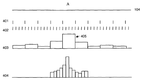
resolution. Figure 4 illustrates an optical fibre 104 and indicates how the
fibre is
divided into sensing portions in the first spatial resolution 401 and the
division of the
fibre at the second spatial resolution.
The sensor may be arranged to swap between different spatial resolutions in a
pre-
determined pattern. For example the sensor may interrogate the fibre with a
certain
number of pulse pairs of the first duration followed by a certain number of
pulse pairs of
a second duration. Alternatively the sensor may operate at the first spatial
resolution
as a default spatial resolution. If an acoustic event above a certain
threshold, and/or
matching a certain characteristic is detected in the signals from any one or
more of the
sensing portions of the fibre, the sensor may swap to the second spatial
resolution.
CA 02780610 2012 05 11
WO 2011/058322 PCT/GB2010/002087
16
As will be clear from the foregoing the second spatial resolution provides
potentially
many more discrete sensing portions of fibre and thus may result in a
significant
processing overhead. In some embodiments therefore the processor may be
arranged
to provide measurement signals from only the longitudinal sensing portions in
the
vicinity of the detected event.
Figure 4 illustrates an acoustic event occurring at position A. The acoustic
waves will
be detected by the fibre 104. Plot 403 shows a histogram representing the
average
acoustic signal intensity for each of the sensing portions of fibre at the
first spatial
resolution. It can be seen that a relatively large disturbance is detected in
the relevant
sensing portion 405. The processor may then switch to the second spatial
resolution
but only process the signals which correspond to the sensing portions of the
second
spatial resolution in the vicinity of section 405 of fibre. Plot 404 shows a
histogram of
the acoustic signal for each of the processed sensing portions at the second
spatial
resolution.
It can be seen that at the second spatial resolution the location of the
acoustic event
along the fibre can be more clearly determined. Further the analysis of the
evolution of
the acoustic signal over one or more of these sensing portions may reveal a
characteristic signature that can be used to classify the event, i.e. identify
the type of
event which would produce such an acoustic response. This may enable the
processor to determine whether the acoustic event is one of interest, for
example
indicative of an intruder or a fault conditions and thus an automated alarm
should be
generated.
As shown in Figure 2 the interrogator may swap between different interrogating
waveforms, and hence between spatial resolutions either in response to event
or as
part of a standard pattern. In another embodiment however two spatial
resolutions
may be simultaneously realised in the same fibre.
Figure 5 shows the output of an interrogator according to this embodiment of
the
invention. A first pulse pair 501 having a first duration is transmitted into
the fibre as
described above. The pulses in the first pulse pair have frequencies fl and f2
respectively. Immediately after the first pulse pair is transmitted a second
pulse pair
502 is transmitted. The pulse in the second pulse pair have a different
separation, and
CA 02780610 2012-05-11
WO 2011/058322 PCT/GB2010/002087
17
optionally different duration also and have frequencies f3 and LI
respectively. The
frequencies are chosen such that f2 ¨ ft does not equal any of fl, f2, f3 or
fa or fa ¨f3.
Similarly f4 ¨f3 does not equal ft, f2, f3 or fit. As described in GB
2,442,745 this
arrangement can allow the two pulse pairs to be almost simultaneously
transmitted into
the fibre (indeed in a different apparatus they could be simultaneous) but the
response
from each to be demodulated separately. In this way signal returns at a first
spatial
resolution may be processed and also signals returns at a second spatial
resolution
may be processed to provide two simultaneous spatial resolutions.
The processor may provide measurement signals at both spatial resolutions for
the
whole of the fibre and may use the signals at both spatial resolutions to
detect events
of interest. Alternatively measurement signals at one of the spatial
resolutions may be
produced for only part of the optical fibre. For instance imagine that the
optical fibre is
deployed along the length of a buried pipeline for detecting interference with
the
pipeline and/or condition monitoring. For most of the pipeline a spatial
resolution of
10m or so may be acceptable and provide optimal monitoring. For some areas
however, there may be other machinery or parts of the pipeline prone to
particular
stress, it may be desired to have a sensor with a spatial resolution of the
order of 1m.
In this embodiment of the present invention the optical fibre can be
interrogated with
lm pulses and 10m pulses. The returns from the 10m pulses would be used for
most
of the pipeline but the 1m pulses would be used for the sensitive portions.
Additionally or alternatively the shorter resolution pulses could be
transmitted but the
returns not processed for at least a section of the fibre until an event is
detected. At
which point the appropriate sensing portions could be analysed in a similar
fashion to
that described above in relation to Figure 3.
In all instances the different spatial resolutions provided by the sensor may
be
predetermined, e.g. there may be a default resolution of10m say and a fine
resolution
of lm say. In some embodiments however the spatial resolution may be
determined I
response the signals detected. For instance the processor may analyse the
signals at
a first spatial resolution and, based on that analysis, choose a spatial
resolution to
apply in future.
It will of course be appreciated from the discussion above that, depending on
where the
event occurs in the optical fibre, and the overall length of fibre, changing
the spatial
CA 02780610 2012 05 11
WO 2011/058322
PCT/GB2010/002087
18
resolution may vary the overall range of the sensor. Therefore for parts of
the optical
fibre which are towards the maximum range of the sensor at the particular
spatial
resolution it might not be possible to reduce the spatial resolution to a
shorter length
and still receive useable signals. However the use of two or more different
spatial
resolution may still be beneficial for the parts of the fibre which are within
the effective
range at both resolutions. The processor may be programmed with a series of
cutoff
ranges for varying the spatial resolution of certain parts of the fibre, i.e.
a list of the
shortest spatial resolution usable if an event occurs of interest occurs in a
certain
range.
Each feature disclosed in the description, and (where appropriate) the claims
and
drawings may be provided independently or in any appropriate combination.