Note: Descriptions are shown in the official language in which they were submitted.
CA 02780668 2012-08-15
50777-301
1
SELF-CLEANING HOUSEHOLD APPLIANCE HAVING A RANGE DOOR
WITH A FULL GLASS INNER SURFACE
[0001]
FIELD OF THE INVENTION
=
[0002] The present invention is directed to a self-cleaning household
appliance having a
door, and more particularly, to a self-cleaning household appliance having a
door with a full
glass inner panel.
BACKGROUND OF THE INVENTION
[0003] Conventional self-cleaning ovens and ranges commonly may include an
oven
door with a traditional metal "plunger" on the inside surface of the door. The
plunger may
CA 02780668 2012-06-22
Attorney Docket No. 2011P04472US
2
include a plurality of glass panels to permit viewing an interior of the over
chamber. Ovens
having self-cleaning features have become popular among consumers and commonly
are offered
by manufacturers on many oven models. In a self-cleaning process, the oven
door commonly is
closed and locked by a mechanical latch to prevent opening during the self-
cleaning process and
then the oven chamber is heated to a high temperature, such as 900 - 1000 F,
to reduce food
pieces or other contaminants in the oven chamber to ash. In this way, the oven
"self-cleans" the
oven chamber, for example, without a user needing to apply a cleaning solution
or solvent to the
surface and/or to scrub the surface.
SUMMARY OF THE INVENTION
[0004] The present invention is directed to a self-clean household cooking
appliance
including a housing having an oven chamber accessible through an opening, the
opening having
a seal surrounding a perimeter of the opening; and a door covering the opening
and moveable
about a hinge between an open position and a closed position. The door
includes a full glass
inner panel that abuts the seal when the door is in a closed position. The
full glass inner panel
includes an inner surface having a first portion and a second portion. The
first portion is adjacent
to a first area within the perimeter of the seal surrounding the opening and
directly exposed to
heating of the oven chamber, and the second portion is adjacent to a second
area outside of the
perimeter of the seal and not being exposed to heating of the oven chamber.
The full glass inner
panel extends substantially from edge-to-edge of the door.
[0005] In this way, the present invention can provide a door for a self-
cleaning oven
having a full inner glass panel that can withstand the high temperatures and
extreme temperature
CA 02780668 2012-06-22
Attorney Docket No. 2011P04472US
=
3
differentials associated with a self-cleaning oven, is easy to wipe and clean,
increases an amount
of space in the cooking chamber, reduces a number of glass panels needed to a
suitable surface
temperature of the door skin, and provides an aesthetically pleasing
appearance for marketing
purposes.
[0006] To provide a better understanding of the invention, a summary of
the problems
with the conventional designs recognized by the present invention along with
the reasons for
improving the arrangement of the conventional self-cleaning oven door and the
corresponding
advantages provided by the present invention will be explained in greater
detail.
[0007] Some conventional appliances, without self-cleaning features, may
include a door
in which the inside surface comprises a solid sheet of glass instead of a
traditional metal
"plunger". The implementation of such glass inner surfaces primarily has been
driven by
marketing objectives and commonly for cosmetic purposes. Such glass inner
surfaces also can
provide practical advantages such as making wiping and cleaning of the inside
surface of an
oven door easier and simpler for a user. However, the known appliances have
not provided an
oven door with a solid sheet of glass for appliances with self-cleaning
features for at least the
following reasons.
[0008] Conventional doors with a traditional metal "plunger" may include
an inner glass
panel that is supported by the plunger and inset from the edges of the plunger
such that the entire
glass panel is disposed inside the opening of the oven chamber. During a self-
cleaning process,
the entire inner glass panel is subjected to heating to the self-cleaning
temperature (e.g., such as
900 - 1000 F). Thus, the entire inner glass is heated to the same temperature
and little or no
temperature differential exists between different areas of the glass.
CA 02780668 2012-06-22
Attorney Docket No. 2011P04472US
4
[0009] An oven door having a solid sheet of glass extending from edge to
edge (i.e., side-
to-side and top-to-bottom) of the inner side of the door has a first, inner
portion of glass covering
the opening to the oven chamber and disposed within a perimeter of a gasket
surrounding the
opening of the oven chamber. However, in stark contrast to a conventional door
with a metal
plunger, the solid sheet of glass also has a second, outer or perimeter
portion of glass that
extends past the gasket surrounding the opening of the oven chamber and to the
edge of the door.
In a self-cleaning process, the inner portion of the full glass inner surface
within the gasket of the
oven chamber opening is subjected to heating along with the rest of the
interior of the oven
chamber up to the self-cleaning temperature (e.g., such as 900 - 1000 F). At
the same time, the
outer portion of the full glass inner surface that extends past the gasket may
remain at or near
room temperature. As a result, an extreme temperature differential may exist
between the heated
inner portion and the room temperature outer portion of the full glass inner
surface during a self-
cleaning process. These extreme temperature differentials can be problematic
for conventional
soda-lime inner glass panels, which commonly have a relatively high
coefficient of thermal
expansion, which ordinarily is defined as the percent change of the original
length (i.e., the
amount of expansion or contraction per unit length) of the material from one
degree change in
temperature (e.g., per degree Kelvin or Celsius). The conventional oven glass
materials having a
relatively high coefficient of thermal expansion may fracture, break, or even
shatter/explode into
pieces when exposed to extreme temperature differentials across the surface of
the glass.
[0010] For example, conventional inner glass panels commonly may be formed
from
glass, such as soda-lime glass, that is capable of withstanding a
predetermined amount of force
(e.g., impact force, for example, resulting from a user dropping a pot or pan
on the door when the
CA 02780668 2012-06-22
Attorney Docket No. 2011P04472US
door is in an open position in order) that may be exerted on the inner glass
in order to comply
with industry and government standards. However, the commonly used glass
materials
ordinarily have a relatively high coefficient of thermal expansion. For
example, soda-lime glass
may have a coefficient of thermal expansion of approximately 9 e-6 with units
of 1/degree K.
During testing, the conventional soda lime glass panels shattered when exposed
to large
temperature differentials across the surface of the glass, which are
associated with heating only a
portion of the glass to a temperature of a self-cleaning cycle of an oven
while another portion
remains at or near room temperature. Therefore, if a full glass inner surface
of a self-cleaning
oven door is formed using the conventional soda-lime inner glass panels, the
inner glass panel
may break, fracture, or even shatter/explode into pieces when subjected to the
extreme
temperature differentials associated with a self-cleaning process. Therefore,
the conventional
soda-lime glass panels are not suitable for a full glass inner surface of an
oven with a self-
cleaning feature.
[00111 The present invention addresses these problems by forming the inner
glass panel
from a transparent ceramic material with a low coefficient of thermal
expansion. For example, a
ceramic material, which can withstand large temperature differentials across
an entire surface
without breaking, can be used for the inner glass. More particularly, the door
can include a full
glass inner panel formed by a transparent ceramic material commonly used, for
example, for
fireplace glass (e.g., Robax or ResistanTM, manufactured by SCHOTT North
America, Inc.),
which can withstand large temperature differentials across its surface without
breaking. In
testing, the present invention recognized that forming the full inner glass
panel from a
transparent ceramic material having, for example, a coefficient of thermal
expansion of
CA 02780668 2012-06-22
Attorney Docket No. 2011P04472US
6
approximately 0 + 0.15 e-6 with units of 1/degree K, was sufficiently low to
prevent the full
inner glass panel from fracturing, breaking, or shattering when exposed to the
temperature
differentials across the surface of the glass associated with a self-cleaning
cycle of an oven. One
of ordinary skill in the art will recognize that the invention is not limited
to the example
materials described herein and can include other suitable materials having low
or very low
coefficients of thermal expansion and that are resistant to large temperature
differentials across
the surface of the glass or thermal shock. In this way, the present invention
can provide a full
glass inner panel that can withstand the inner portion of the full glass inner
surface within the
gasket of the oven chamber opening being subjected to heating to the self-
cleaning temperature
while the outer or perimeter portion of the full glass inner surface that
extends past the gasket
remains at or near room temperature.
100121 An exemplary embodiment is directed to a self-clean household
cooking
appliance including a housing having an oven chamber accessible through an
opening, the
opening having a seal surrounding a perimeter of the opening; and a door
covering the opening
and moveable about a hinge between an open position and a closed position. The
door includes a
full glass inner panel that abuts the seal when the door is in a closed
position. The full glass
inner panel includes an inner surface having a first portion and a second
portion. The first
portion is adjacent to a first area within the perimeter of the seal
surrounding the opening and
directly exposed to heating of the oven chamber, and the second portion is
adjacent to a second
area outside of the perimeter of the seal and not being exposed to heating of
the oven chamber.
The full glass inner panel extends substantially from edge-to-edge of the
door.
81614074
6a
[0012a] According to one aspect of the present invention, there is provided a
household
cooking appliance comprising: a housing having an oven chamber accessible
through an
opening, the opening having a seal surrounding a perimeter of the opening,
wherein the
household cooking appliance includes a self-cleaning cycle for cleaning the
oven chamber; a
door covering the opening and moveable about a hinge between an open position
and a closed
position, the door including a full transparent ceramic inner panel having a
low coefficient of
thermal expansion capable of withstanding temperature differentials across the
full transparent
ceramic inner panel during the self-cleaning cycle, the full transparent
ceramic inner panel
having an inner surface that abuts the seal when the door is in a closed
position, the inner
surface including a first portion and a second portion, the first portion
being adjacent to a first
area within the perimeter of the seal surrounding the opening and directly
exposed to heating
of the oven chamber, and the second portion being adjacent to a second area
outside of the
perimeter of the seal and being insulated from the heating of the oven chamber
by the seal; an
outer door skin having an outer glass panel, wherein the full transparent
ceramic inner panel is
configured to float with respect to the outer door skin such that the door is
capable of
distributing impact forces exerted on the full transparent ceramic inner panel
to thereby
prevent breakage of the full transparent ceramic inner panel; and shock-
absorbing means for
absorbing and distributing shocks and impacts on the full transparent ceramic
inner panel with
respect to the outer door skin.
10012b] According to another aspect of the present invention, there is
provided a
household cooking appliance comprising: a housing having an oven chamber
accessible
through an opening, the opening having a seal surrounding a perimeter of the
opening,
wherein the household cooking appliance includes a self-cleaning cycle for
cleaning the oven
chamber; a door covering the opening and moveable about a hinge between an
open position
and a closed position, the door including a full transparent ceramic inner
panel having a low
coefficient of thermal expansion capable of withstanding temperature
differentials across the
full transparent ceramic inner panel during the self-cleaning cycle, the full
transparent ceramic
inner panel having an inner surface that abuts the seal when the door is in a
closed position,
the inner surface including a first portion and a second portion, the first
portion being adjacent
to a first area within the perimeter of the seal surrounding the opening and
directly exposed to
CA 2780668 2019-01-11
81614074
6b
heating of the oven chamber, and the second portion being adjacent to a second
area outside
of the perimeter of the seal and being insulated from the heating of the oven
chamber by the
seal; an outer door skin having an outer glass panel, wherein the full
transparent ceramic inner
panel is configured to float with respect to the outer door skin such that the
door is capable of
distributing impact forces exerted on the full transparent ceramic inner panel
to thereby
prevent breakage of the full transparent ceramic inner panel; and means for
movably
supporting the full transparent ceramic inner panel with respect to the outer
door skin without
penetrating through the inner surface of the full transparent ceramic inner
panel.
[0012c] According to still another aspect of the present invention, there is
provided a
household cooking appliance comprising: a housing having an oven chamber
accessible
through an opening, the opening having a seal surrounding a perimeter of the
opening,
wherein the household cooking appliance includes a self-cleaning cycle for
cleaning the oven
chamber; and a door covering the opening and moveable about a hinge between an
open
position and a closed position, wherein the door comprises: an outer door
skin; a full
transparent ceramic inner panel having a low coefficient of thermal expansion
capable of
withstanding temperature differentials across the full transparent ceramic
inner panel during
the self-cleaning cycle, the full transparent ceramic inner panel having an
inner surface that
abuts the seal when the door is in a closed position, the inner surface
including a first portion
and a second portion, the first portion being adjacent to a first area within
the perimeter of the
seal surrounding the opening and directly exposed to heating of the oven
chamber, and the
second portion being adjacent to a second area outside of the perimeter of the
seal and being
insulated from the heating of the oven chamber by the seal; means for movably
supporting the
full transparent ceramic inner panel with respect to the outer door skin
without penetrating
through the inner surface of the full transparent ceramic inner panel; and
shock-absorbing
means for absorbing and distributing shocks and impacts on the full
transparent ceramic inner
panel with respect to the outer door skin, wherein the full transparent
ceramic inner panel is
configured to float with respect to the outer door skin such that the door is
capable of
distributing impact forces exerted on the full transparent ceramic inner panel
to thereby
prevent breakage of the full transparent ceramic inner panel.
CA 2780668 2019-01-11
CA 02780668 2012-06-22
Attorney Docket No. 2011P04472US
7
[0013] The exemplary embodiments can provide a self-cleaning oven door for
a self-
cleaning oven having a full glass inner panel that is capable of withstanding
the high
temperatures and extreme temperature differentials associated with a self-
cleaning oven across
its surface without breaking, while also being capable of fixing and
supporting the full glass
inner panel and absorbing shocks or impacts on the glass to comply with
ratings agencies and
industry/government standards. The exemplary embodiments can provide a self-
cleaning oven
door with a full inner glass surface that is glass and that is easy to wipe
clean, thereby providing
a clean aesthetic appearance. The exemplary self-cleaning oven door can
include a suspension
system that absorbs impact to the full glass inner panel to resist breakage of
the ceramic panel.
The exemplary self-cleaning oven door can increase an amount of space in the
cooking chamber
by eliminating the door "plunger," and thus, eliminating an intrusion of the
door into the space
within the oven chamber. The exemplary self-cleaning oven door also can reduce
a number of
glass panels needed to a suitable surface temperature of the door skin. The
full glass inner panel
of the exemplary self-cleaning oven door also can provide a clean cosmetic
appearance that is
desirable to many users.
[0014] The present invention further recognizes, however, that forming the
inner glass
panel of a door for a self-cleaning oven from a transparent ceramic material
with a low
coefficient of thermal expansion presents a unique set of difficulties and
problems, which may
not be present in ovens without self-cleaning features.
[0015] For example, the present invention recognizes that a transparent
ceramic material
with a low coefficient of thermal expansion commonly may be brittle compared
to conventional
glass panels. As a result, a glass panel formed from transparent ceramic
material with a low
CA 02780668 2012-06-22
Attorney Docket No. 2011P04472US
8
coefficient of thermal expansion may not be capable of withstanding the forces
(e.g., impact
forces) that may be exerted on an inner glass panel of an oven, for example,
by a user dropping a
pot or pan on the door when the door is in an open position, and thus, may not
comply with
ratings agencies and industry/government standards. The present invention has
found that a
glass panel formed by simply replacing the conventional glass with a glass
panel formed from
transparent ceramic material commonly may fail to comply with the applicable
ratings agency
and industry/government standards for oven doors, such as one or more drop
tests in which a
mass is dropped on the glass panel of an open door from a predetermined
height. Moreover, the
present invention recognizes that conventional devices for mounting hinges, a
door latch, or one
or more of the glass panels of the door may not be suitable for a door having
a full transparent
ceramic inner panel extending from edge to edge of the door.
[0016] The present invention addresses these problems by supporting the
full glass inner
panel, which is formed from a transparent ceramic material with a low
coefficient of thermal
expansion, with a shock absorbing fixation or support means for distributing
forces exerted on
the glass to prevent breakage and comply with ratings agencies and
industry/government
standards.
[0017] An exemplary embodiment is directed to means for fixing and
supporting the full
glass inner panel and for absorbing shocks or impacts on the glass such that
an impact to the
glass can be distributed over the glass without breaking the glass, and such
that the glass can be
configured to "float" or move with respect to other components of the door to
minimize or avoid
the glass contacting firm surfaces of the door assembly. The exemplary means
for fixing and
supporting the full glass inner panel and for absorbing shocks or impacts on
the glass can include
CA 02780668 2012-06-22
Attorney Docket No. 2011P04472US
9
one or more insulation components and flexible metal parts that permit the
glass to "float" or
move with respect to the components of the door.
[0018] For purposes of this disclosure, the term "float" means that the
full transparent
ceramic inner glass is configured to move by one or more predetermined
distances in one or
more directions with respect to the door, such as a side-to-side direction
with respect to the door,
a top-to-bottom direction with respect to the door, and a front-to-back
direction with respect to
the door (i.e., approximately normal to a planar surface of the glass) or a
combination thereof.
[0019] For purposes of this disclosure, the term "inner glass" is defined
as the glass panel
of the door that is disposed on an inner side of the door that is closest to
an opening of the oven
chamber. The term "outer glass" is defined as the cosmetic glass panel of the
door skin that is
furthest from the opening of the oven chamber. The term "middle glass" is
defined as a glass
panel that is disposed between the inner glass and the outer glass.
[0020] In another embodiment, a coating (e.g., an energy+ coating) that
commonly may
be used on fireplaces may be provided on the inner glass to minimize or reduce
external door
surface temperatures to an acceptable level. Additionally, the door can
include a middle glass
that is supported between the full glass inner panel and the door skin (outer)
glass panel. The
middle glass can include a tin oxide coating on both sides and can serve as a
part of the flexible
mounting/suspension system for the inner glass panel. In this embodiment, the
door skin glass
may not have a heat reflective coating.
100211 Moreover, according to the present invention, an embodiment may
control a
temperature on the exterior of the self-cleaning oven door to be within
acceptable limits such that
a predetermined safe temperature can be maintained on the exterior surfaces of
the door (e.g.,
CA 02780668 2012-08-15
50777-301
door skin, outer glass, etc.), even at high self-cleaning temperatures
associated with a self-
cleaning process.
[0021a] In accordance with an another embodiment of the invention,
there is provided a
household cooking appliance comprising: a housing having an oven chamber
accessible
5 through an opening, the opening having a seal surrounding a perimeter of
the opening; and a
door covering the opening and moveable about a hinge between an open position
and a closed
position, the door including a full glass inner panel having a low coefficient
of thermal
expansion, the full glass inner panel having an inner surface that abuts the
seal when the door
is in a closed position, the inner surface including a first portion and a
second portion, the first
10 portion being adjacent to a first area within the perimeter of the seal
surrounding the opening
and directly exposed to heating of the oven chamber, and the second portion
being adjacent to
a second area outside of the perimeter of the seal and being insulated from
the heating of the
oven chamber by the seal.
[0022] Other features and advantages of the present invention will
become apparent to
those skilled in the art upon review of the following detailed description and
drawings.
BRIEF DESCRIPTION OF THE DRAWINGS
[0023] These and other aspects and features of embodiments of the
present invention
will be better understood after a reading of the following detailed
description, together with
the attached drawings, wherein:
Figures lA - 1C are a front view, a side view, and a perspective view,
respectively, of a household appliance according to an exemplary embodiment of
the
invention.
Figure 2 is an exploded view of the exemplary household appliance of
FIGS. lA - 1C.
CA 02780668 2012-08-15
50777-301
1 Oa
Figure 3 is a front perspective view of a household appliance according to
another
exemplary embodiment of the invention.
Figure 4 is a front perspective view of a household appliance according to
another
exemplary embodiment of the invention.
Figure 5 is a front perspective view of a self-cleaning oven door according to
an
=
exemplary embodiment of the invention.
Figures 6A - 6D are a rear perspective view of a self-cleaning oven door, a
partial
perspective view of an edge lip of the self-cleaning oven door of Figure 6A, a
partial
perspective view of a hinge cover of the self-cleaning oven door taken at VI-B
of Figure 6A,
CA 02780668 2012-06-22
= Attorney Docket No. 2011P04472US
11
and another partial perspective view of the hinge cover of the self-cleaning
oven door taken at
VI-C of Figure 6A, respectively, according to an exemplary embodiment of the
invention.
Figure 7 is a rear perspective view of a transparent ceramic inner panel of a
self-
cleaning oven door according to an exemplary embodiment of the invention.
Figure 8 is a rear perspective view of a partially assembled self-cleaning
oven
door having an inner glass shock absorbing support system according to an
exemplary
embodiment of the invention.
Figures 9A - 9C are a front plan view, a side view, and a partial perspective
view
of elements of an inner glass shock absorbing support system, respectively,
and Figure 9D is a
partial cross-sectional view taken at section IX-D - IX-D of Figure 9C,
according to an
exemplary embodiment of the invention.
Figures 10A - 10C are a partial perspective view of a door hinge assembly and
hinge retainer, a perspective view of a hinge retainer, and a front view of a
hinge retainer of an
inner glass shock absorbing support system, respectively, according to an
exemplary
embodiment of the invention.
Figure 11 is another rear perspective view of a partially assembled self-
cleaning
oven door having elements of an inner glass inner glass shock absorbing
support system
according to an exemplary embodiment of the invention.
Figure 12 is a rear perspective view of a partially assembled self-cleaning
oven
door having elements of an inner glass shock absorbing support system and
elements of a
middle glass mounting system according to exemplary embodiments of the
invention.
CA 02780668 2012-06-22
Attorney Docket No. 2011P04472US
12
Figure 13 is a perspective view of a lower retainer of a middle glass mounting
system according to an exemplary embodiment of the invention.
Figure 14 is a rear plan view of a partially assembled self-cleaning oven door
having elements of a middle glass mounting system and elements of an outer
glass mounting
system according to exemplary embodiments of the invention.
Figures 15A - 15D are a side perspective view of a left-hand side bracket, a
side
view of a left-hand side bracket, a side perspective view of a right-hand side
bracket, and an end
view of a left-hand side bracket, respectively, of a middle glass mounting
system and an outer
glass mounting system according to exemplary embodiments of the invention.
Figure 16 is a rear perspective view of a partially assembled self-cleaning
oven
door having upper and lower air ramps/guides according to an exemplary
embodiment of the
invention.
Figures 17A and 17B are rear perspective views of an upper and a lower air
ramp/guide, respectively, according to an exemplary embodiment of the
invention.
Figure 18 is a rear perspective view of a partially assembled self-cleaning
oven
door having an outer glass mounting system according to an exemplary
embodiment of the
invention.
Figures 19A and 19B are a perspective view and an end view of an outer glass
bracket, respectively, according to an exemplary embodiment of the invention,
and Figure 19C
is a perspective partial assembly view of an outer glass mounting system
according to an
exemplary embodiment of the invention.
CA 02780668 2012-06-22
= Attorney Docket No. 2011P04472US
13
Figure 20 is a rear perspective view of a partially assembled self-cleaning
oven
door having elements of an outer glass mounting system according to an
exemplary
embodiment of the invention.
Figure 21 is another rear perspective view of a partially assembled self-
cleaning
oven door having elements of an outer glass mounting system according to an
exemplary
embodiment of the invention.
Figures 22A and 22B are a perspective view and an end view, respectively, of
an
element of an outer glass mounting system according to an exemplary embodiment
of the
invention.
Figure 23A is a perspective view of a door latch, and Figures 23B and 23C are
partial perspective views of a latch system of a self-cleaning oven door
according to an
exemplary embodiment of the invention.
Figures 24A and 24B are partial perspective views of a latch system of a self-
cleaning oven door according to an exemplary embodiment of the invention.
Figure 25A is partial perspective view of a door having a hinge retainer
assembly
according to an exemplary embodiment of the invention, Figure 25B is a partial
perspective
view of a door having a hinge retainer assembly according to another exemplary
embodiment of
the invention, and Figure 25C is a cut-away, partial side view of a door
having the hinge
retainer assembly of Figure 25A.
CA 02780668 2012-06-22
Attorney Docket No. 2011P04472US
=
14
DETAILED DESCRIPTION OF THE EXEMPLARY EMBODIMENTS OF THE
INVENTION
[0024] The present invention now is described more fully hereinafter with
reference to
the accompanying drawings, in which embodiments of the invention are shown..
This invention
may, however, be embodied in many different forms and should not be construed
as limited to
the embodiments set forth herein; rather, these embodiments are provided so
that this disclosure
will be thorough and complete, and will fully convey the scope of the
invention to those skilled
in the art.
[0025] Referring now to the drawings, Figures lA - 25C illustrate
exemplary
embodiments of a self-cleaning household appliance having an oven door with a
full glass inner
surface. Prior to describing the exemplary embodiments of a full glass inner
panel in greater
detail, and to provide a better understanding of the invention, this
disclosure will first describe
examples a self-cleaning household appliance and an exemplary oven door of a
self-cleaning
household appliance. Other features and components of the oven door, including
examples of an
inner glass suspension system, middle mounting system, and outer glass
mounting system, also
will be described following the description of the full glass inner panel to
provide a better
understanding of the overall arrangement and features of the exemplary oven
door. To provide a
better understanding of the invention, the description will start with the
components of an
innermost side of the door and progress toward the front door skin of the
door.
[0026] With reference to FIGS. lA - 1C, a household cooking appliance can
include, for
example, a gas cooking range 100 having a housing 102 including one or more
cooking or
warming devices, such as a cooktop, gas oven, electric oven, steam oven,
convection oven,
81614074
and/or warming drawer. In other embodiments, the appliance 100 can include one
or more oven
cooking chambers without a cooktop. In other embodiments, the appliance 100
can include a
standalone appliance, wall mounted appliance, such as a stand-alone oven or
wall mounted oven.
For example, the appliance housing 102 can include a cooktop 104 and control
panel 106. The
cooktop 104 can include, for example, a gas cooktop having a plurality of gas
burners, or other
types of coolctops, such as an electric cooktop, an induction cooktop, or the
like. The exemplary
household appliance 100 can include one or more doors, such as a baking oven
door 200, a steam
oven door 300, and/or a warming drawer door 400 for providing access to one or
more chambers
of the housing 102. The housing 102 can include pedestal feet 108 for example
for supporting
the stand alone appliance and a kick panel 110.
[00271 Referring to FIG. 2, an exploded view of the appliance 100 of
FIGS. lA - IC
includes housing parts 102A, 102B, 102C, 10213, the cooktop 104,
sealing arrangement 101, and control panel 106, a
baking oven door 200, a steam oven door 300, and a warming drawer door 400,
and kick panel
110. For example, the housing of the exemplary household appliance 100 shown
in FIG. 2 can
include left-hand and right-hand sidewalls 102A, 102B and one or more rear
panels 102D on a
frame 103. The exemplary appliance 100 can include other devices and features,
such as, for
example, a backsplash or venting device 102C, hideaway label plate 105, etc.
The frame 103 can
include one or more chambers for cooking or warming devices, such as a baking
oven chamber
112, steam oven chamber 113, and/or warming drawer chamber 114, each covered
by the baking
oven door 200, steam oven door 300, and warming drawer door 400, respectively.
[0028j The exemplary embodiments are not limited to the oven 100 of
FIGS. IA - IC
having the baking oven door 200, steam oven door 300, and warming drawer door
400, and can
CA 2780668 2019-01-11
CA 02780668 2012-06-22
Attorney Docket No. 2011P04472US
= 16
be applied to other appliances, such as the appliance 100 illustrated in FIGS.
3 and 4. Like
reference numerals are used to identify the features of the embodiments of the
appliance 100 in
FIGS. IA -4. The features shown in FIGS. 3 and 4 are similar to, or the same
as, the features of
FIGS. IA - 1C, and therefore, are not repeated.
100291 With reference to FIG. 5, an exemplary embodiment of a self-
cleaning oven door
200 (as illustrated in the examples of FIGS. 1A - 4) will now be described.
[0030] The self-cleaning oven door 200 can include a door skin 202
having a front
surface 202a that faces away from the oven chamber, side surfaces 202b, a
lower surface (not
shown), and a top surface 202c. The top surface 202c can include a plurality
of vents 203 for
permitting air flow through the door. The door skin glass may be provided with
or without a
heat reflective coating. The door 200 can include a handle 204 supported from
the door skin 202
by handle mounts 206. The door 200 can include an outer glass panel 298 and a
plurality of
interior glasses panels (e.g., middle glass, inner glass; not shown in FIG. 5)
for viewing an
interior of the oven chamber through the door 200 while keeping a temperature
of the outer glass
panel 298 at an acceptable temperature. The door 200 can include hinge claws
212 to facilitate
pivoting of the door 200 with respect to the appliance housing for opening and
closing the oven
chamber.
[0031] With reference to FIG. 6A, an exemplary embodiment of the door
200 of FIG. 5
can include a full glass panel formed by a transparent ceramic inner panel 220
(e.g., a full glass
ceramic inner panel, which is shown in greater detail in FIG. 7). The door 200
can include a lip
205 extending for example along an inner edge of the top surface 202c. The lip
205 can be
integrally formed with the top surface 202c or formed as a separate component
coupled to the top
CA 02780668 2012-06-22
Attorney Docket No. 2011P04472US
17
surface 202c. The top surface 202c can include a latch cover 216 having a
guide opening 219 for
receiving and guiding a door lock to a latch plate (not shown), which may be
disposed under the
latch cover 216. The latch cover 216 can be integrally formed with the top
surface 202c or
formed as a separate part. As shown in FIG. 6A, the door 200 can include hinge
covers 214 that
are adjacent to or surround the hinge claws 212, which facilitate pivoting of
the door 200 with
respect to the appliance housing for opening and closing the oven chamber. The
hinge cover 214
can include an opening for accommodating the hinge claw 212 and also covering
portions of a
hinge assembly within the door 200 from view. The hinge cover 214 can be
formed, for
example, from metal such as stainless steel. The hinge cover 214 also can be
part of a system
that retains the ceramic transparent panel 220 in the door 200 by restraining
the panel 200 at the
bottom of the door 200 while at the same time covering the hinge assembly, as
described in more
detail with reference to FIGS. 6B - 6D.
[0032] With
reference again to FIG. 6A, an example of a transparent ceramic inner panel
220 includes a first inner portion 222 that is disposed adjacent to an area
within a gasket (not
shown) surrounding the opening of the oven chamber opening (e.g., 112 in FIG.
2) and sealing
the door 200 to the opening. The area of the transparent ceramic inner panel
220 that contacts
and seals against the gasket (not shown) when the door 200 is closed is
exemplarily illustrated by
the dashed line 223. The transparent ceramic inner panel 220 includes a
second, outer or
perimeter portion 224 that is disposed adjacent to an area of the oven outside
of the gasket (not
shown) that surrounds the opening to the oven chamber, or in other words,
outside the area
illustrated by the dashed line 223. As a result of this arrangement, during a
self-cleaning
operation, the first inner portion 222 is subjected to heating to the self-
cleaning temperature
CA 02780668 2012-06-22
Attorney Docket No. 2011P04472US
18
along with the oven chamber, while the second, outer or perimeter portion 224
remains at or near
room temperature, thereby subjecting the transparent ceramic inner panel 220
to a large
temperature differential between portions 222 and 224. As shown in FIG. 6A,
the transparent
ceramic inner panel 220 can extend substantially from edge to edge of the door
200 in both the
width direction and the height direction of the door 200 (i.e., from side 202b
to side 202b in the
width direction and from the top surface 202c to the bottom surface (202d in
FIG. 6D) in the
height direction). In other embodiments, the transparent ceramic inner panel
220 may be
configured to extend to an area adjacent to one or more of the sides, top, and
bottom of the door
that is outside of the area illustrated by the dashed line 223.
[0033] With reference to the enlargements VI-B and VI-C of FIG. 6A, which
are
illustrated in FIGS. 6B - 6D, the exemplary door 200 can be assembled by
inserting a top edge of
the transparent ceramic inner panel 220 under the lip 205 of the top surface
202e and then resting
the transparent ceramic inner panel 220 into position, as shown in FIG. 6B.
Each of the hinge
covers 214 then can be installed over at least a portion of each lower corner
of the transparent
ceramic inner panel 220 and coupled to the lower surface 202d of the door 200
using fasteners,
such as one or more screws, as shown in FIGS. 6C and 6D. The hinge cover 214
can include, for
example, a side portion that is disposed adjacent to the side 202b and secures
the transparent
ceramic inner panel 220 in a dimension extending in a direction of a width of
the door (i.e., from
side 202b to side 202b). The hinge cover 214 also can include, for example, a
bottom portion
that is disposed adjacent to the bottom 202d and secures the transparent
ceramic inner panel 220
in a first vertical direction of a height of the door extending from the top
202c toward the bottom
202d. The lip 205 can secure the transparent ceramic inner panel 220 in a
second vertical
CA 02780668 2012-06-22
Attorney Docket No. 2011P04472US
19
direction of the height of the door extending from the bottom 202d toward the
top 202c. In this
way, the transparent ceramic inner panel 220 can be secured in all three
dimensions by the
combination of the lip 205 and the hinge cover 214, for example, without
openings or fasteners
extending through the transparent ceramic inner panel 220. In an embodiment, a
suitable amount
of clearance can be provided between the transparent ceramic inner panel 220
and the lip 205
and/or the hinge cover 214 such that the transparent ceramic inner panel 220
can "float" in the
mounted position to allow for some movement for impact absorption and/or
growth/expansion of
the panel 220 during heating.
[0034] With reference to FIG. 7 an exemplary embodiment of the transparent
ceramic
inner panel 220 will now be described.
[0035] The transparent ceramic inner panel 220 can include a first inner
portion 222 that
is disposed adjacent to an area within a gasket (not shown) surrounding the
opening of the oven
chamber opening (e.g., 112 in FIG. 2) and sealing the door 200 to the opening.
The area of the
transparent ceramic inner panel 220 that contacts and seals against the gasket
(not shown) when
the door 200 is closed is exemplarily illustrated by the dashed line 223. The
transparent ceramic
inner panel 220 can include a second, outer or perimeter portion 224 that is
disposed adjacent to
an area of the oven outside the area illustrated by the dashed line 223. In
this example, the
transparent ceramic inner panel 220 can include a hinge cutout 226 at each
lower corner for
accommodating or providing clearance for the door hinges, for example, without
having
openings or components, such as a hinge or screw, penetrating the transparent
ceramic inner
panel 220. The hinge cutout 226 at each corner also can provide a surface for
engaging the hinge
covers (shown in FIGS. 6A - 6D) to secure the transparent ceramic inner panel
220 in two
CA 02780668 2012-06-22
Attorney Docket No. 2011P04472US
dimensions. The transparent ceramic inner panel 220 can include a latch cutout
228 formed in a
top edge of the panel 220 for accommodating or providing clearance for a door
latch (not shown
in FIG. 7), for example, without having openings or components, such as a
latch or screw,
penetrating the transparent ceramic inner panel 220.
[0036] The transparent ceramic inner panel 220 can have a low coefficient
of thermal
expansion capable of withstanding large temperature differentials across an
entire surface
without breaking. More particularly, the transparent ceramic inner panel 220
can be formed by a
transparent ceramic material commonly used, for example, for fireplace glass
(e.g., Robax or
ResistanTM, manufactured by SCHOTT North America, Inc.), which can withstand
large
temperature differentials across its surface without breaking, and thus, may
withstand the first
inner portion 222 of the full glass inner surface being subjected to heating
to the self-cleaning
temperature while the second, outer or perimeter portion 224 of the full glass
inner surface
remains at or near room temperature. In another embodiments, the transparent
ceramic inner
panel 220 may include a coating such as a heat reflective coating (e.g.,
Energy Plus coating),
which commonly may be used on fireplace glass, to assist with minimizing or
reducing an
external surface temperature of the door to an acceptable level.
[0037] With reference to FIGS. 8 - 11, an exemplary embodiment of an inner
glass shock
absorbing support system will now be described.
[0038] FIG. 8 illustrates the door 200 with the transparent ceramic inner
panel 220
removed. As shown in FIG. 8, the door 200 can include an inner glass shock
absorbing support
system having an energy absorbing support means (e.g., shock absorbing support
means, such as
230 or 230 in combination with 234 and/or 242, 244) for evenly, flexibly, and
resiliently
CA 02780668 2012-06-22
Attorney Docket No. 2011P04472US
21
supporting the transparent ceramic inner panel 220 in a manner that permits
the transparent
ceramic inner panel 220 to "float" in the mounted position to allow for some
movement for
shock/impact absorption. In this way, the shock absorbing support means can
absorb and
distribute forces (e.g., shock or impact forces from a dropped pot or pan,
etc.) exerted on the
transparent ceramic inner panel 220 to prevent the panel 220 from breaking or
fracturing and to
enable the panel 220 to comply with ratings agencies and industry/government
standards.
[0039] More particularly, the shock absorbing support means can include,
for example,
one or more flexible, compressible, or resilient parts or mounts configured to
absorb and
distribute forces exerted on the transparent ceramic inner panel 220, such as
forces exerted by a
user dropping a pot or pan on the open door while loading or unloading the
cooking appliance.
In the example illustrated in FIG. 8, the shock absorbing support means can
include a flexible,
deflectable, or resilient metal support 230 or the like for suspending the
transparent ceramic
inner panel 220 within the door 200 in a manner that flexibly supports a
surface of the
transparent ceramic inner panel 220 and that permits the transparent ceramic
inner panel 220 to
"float" in the mounted position to allow for some movement for impact
absorption. An example
of a deflectable metal support 230 will be described in greater detail with
reference to FIGS. 9A -
9D.
100401 The shock absorbing support means further can include a first
insulation layer 234
surrounding the deflectable metal support 230. The first insulation layer 234
can be secured
using one or more hangers (not shown) that suspend the first insulation layer
234 in position
from one or more components of the door 200. A portion of the first insulation
layer 234 can
flexibly and resiliently support an interior surface of the transparent
ceramic inner panel 220. A
CA 02780668 2012-06-22
Attorney Docket No. 2011P04472US
= 22
portion of the first insulation layer 234 optionally can extend under at least
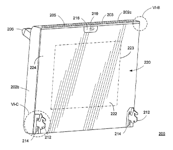
a portion of the
deflectable support 230. The first insulation layer 234 also can assist with
reducing heat transfer
from the transparent ceramic inner panel 220 to the other components of the
door, such as the
middle glass panel or outer glass panel, thereby assisting with reducing the
temperature of the
outer glass panel. The first insulation layer 234 can function alone or in
cooperation with the
deflectable metal support 230. An example of a shock absorbing support means
including a
deflectable metal support 230 and insulation layer 234 will be described in
greater detail with
reference to FIGS. 9A, 9B, and 9D.
100411 With reference again to FIG. 8, the door 200 can include a
hinge assembly 240 on
each side, such as an off-the-shelf hinge assembly. The shock absorbing
support means further
can include a second insulation layer 242 disposed on a surface of each hinge
assembly 240 that
flexibly supports an interior surface of the transparent ceramic inner panel
220. The second
insulation layer 242 can be secured to the hinge assembly 240 using, for
example, one or more
movable or resilient insulation retainers 244, which will be described in
greater detail with
reference to FIGS. 10A - 10C.
10042] As shown in FIG. 8, the transparent ceramic inner panel 220
can be supported at a
plurality of locations by one or more of a deflectable metal support 230, a
first insulation layer
234, a second insulation layer 242, and/or an insulation retainer 244. One of
ordinary skill in the
art will recognize that all of the support means are not necessary and various
combinations of
these elements can support the transparent ceramic inner panel 220 in a
"floating" manner (i.e.,
movable manner) to provide impact absorption. The door 200 also can include
additional or
alternative flexible support means in combination with the illustrated
examples. The present
CA 02780668 2012-06-22
Attorney Docket No. 2011P04472US
23
invention is not limited to the illustrated examples and other flexible
support means are
contemplated by the present invention. According to the exemplary embodiment,
the shock
absorbing support means can provide controlled movement (e.g., limited
controlled movement)
to absorb energy exerted on the transparent ceramic inner panel 220 and
prevent breakage of the
transparent ceramic inner panel 220.
[0043] An exemplary embodiment of a deflectable metal support 230, which
may form a
part of the inner glass shock absorbing support system, will now be described
with reference to
FIGS. 9A - 9D.
[0044] As shown in FIGS. 9A - 9D, the inner glass shock absorbing support
system can
include a support 230 formed for example by a thin, flexible metal support
frame disposed
around a perimeter of a viewing area through the glass panels of the door 220.
In the example,
the support 230 includes a rectangular frame having a plurality of sides 230a,
230b, 230c, and
230d. The sides of the support 230 can be integrally formed or coupled
together to form a frame.
The exemplary embodiment is illustrated with a rectangular-shaped frame.
However, the frame
can have other shapes, such as a circular-shaped frame. In other embodiments,
the support 230
can be formed from separate elements that are not linked together. For
example, the sides 230a,
230b, 230c, and 230d can be individually mounted or suspended within the door
to flexibly
support areas or regions of the panel 220.
[0045] With reference again to the example support 230 illustrated in
FIGS. 9A - 9D, the
sides 230a, 230b, 230e, and 230d can be shaped such that a portion of the
sides 230a, 230b,
230c, and 230d is capable of flexing, deflecting, or otherwise moving when a
force or impact
CA 02780668 2012-06-22
Attorney Docket No. 2011P04472US
24
force is exerted on the support 230 to absorb or distribute the forces and
prevent breakage of the
transparent ceramic inner panel 220.
[0046] As shown in FIGS. 9A - 9D, a first insulation layer 234 optionally
can extend
around a perimeter of the support 230. The first insulation layer 234 can
include an opening that
corresponds to a perimeter size and shape of the support 230 such that the
first insulation layer
234 fits snugly around the support 230. The first insulation layer 234 can
have a uniform
thickness to evenly support the underside of the transparent ceramic inner
panel 220. In other
embodiments, the insulation layer 234 can have an uneven thickness, for
example, to provide
additional support or impact absorption in particular areas, such as areas
that are more highly
prone to impact forces or areas that are directly supported by other shock
absorbing support
means such as the support 230. As shown in FIGS. 9A and 9B, the sides 230a,
230b, 230c, and
230d can have a size and shape such that at least a portion of the first
insulation layer 234 is
disposed under a portion of one or more of the sides 230a, 230b, 230c, and
230d. The portion of
the first insulation layer 234 can provide additional support and/or
resiliency for the portion of
the sides 230a, 230b, 230c, and 230d.
100471 As shown in the example illustrated in FIGS. 9A - 9D, each of the
sides 230a,
230b, 230c, and 230d can include a wall (e.g., a vertical or angled wall) on a
side facing an
interior of the support 230, with the first insulation layer 234 being
disposed on an outside of the
vertical wall. In this way, the sides 230a, 230b, 230c, and 230d of the
support 230 can be
configured to block the interior edges of the first insulation layer 234 from
view through the
viewing area of the glass panels (see e.g., V1 in FIG. 8), thereby improving
the cosmetic
appearance of the door.
CA 02780668 2012-06-22
Attorney Docket No. 2011P04472US
[0048] As shown in FIG. 9C, the support 230 can be formed from a thin
metal part or
thin, perforated metal part such that the support 230 can flex at one or more
locations to absorb
impact energy. For example, the support 230 can formed or bent in a way that
permits the
support to flex at one or more locations. In other examples, the support 230
can include a
plurality of perforations or slots 231 disposed between connecting portions
232. In this example,
the perforations are oriented in a lengthwise direction of the support,
thereby enabling the
support 230 to be flexible along the entire length of the support to evenly
support the transparent
ceramic inner panel 220. The perforations or slots 231 and connecting portions
232 can be
disposed, for example, along a bend in the support 230 such that the support
230 can easily flex
or fold along the bend. By providing a thin support or a support with
perforations or slots 231,
the embodiments can provide an additional advantage of reducing an amount of
material of the
support 230, which may minimize or reduce an amount of heat absorbed by the
support 230, for
example, when the oven is at high temperatures such as self-cleaning
temperatures. In this way,
the exemplary support 230 can minimize an effect of the support 230 acting
like a heat sink, and
thereby assist with keeping the exterior surface of the door cool.
[0049] As schematically illustrated in FIG. 9D, the support 230 can
include a plurality of
portions configured to be flexible or movable to absorb a force exerted on the
transparent
ceramic inner panel 220. The support 230 can be disposed between the
transparent ceramic inner
panel 220 and a middle glass panel 250 of the door. The insulation layer 234
can be disposed
such that at least a part of the layer 234 is disposed under a portion of the
support 230. In
operation, when a force F is exerted on the transparent ceramic inner panel
220, for example in a
direction shown by the arrows in FIG. 9D, the support 230 can flex or move in
the direction of
CA 02780668 2012-06-22
Attorney Docket No. 2011P04472US
26
the force F, thereby permitting the transparent ceramic inner panel 220 to
move downward in the
direction of the force F and absorbing the impact on the transparent ceramic
inner panel 220 to
prevent breaking of the transparent ceramic inner panel 220. The support 230
and/or the surface
of the transparent ceramic inner panel 220 can push against the first
insulation layer 234 to
compress the first insulation layer 234, thereby further absorbing the impact
energy on the
transparent ceramic inner panel 220. The support 230 and/or the first
insulation layer 234 can
function as a spring system or a spring/damper system for absorbing the impact
forces on the
transparent ceramic inner panel 220.
100501 One of ordinary skill in the art will recognize that the support
230 can be
configured in a variety of ways and can have a variety of sizes and shapes
configured to provide
impact absorption and/or to cooperate with the insulation layer 234. The
support 230 can include
linear portions or curved portions that permit the support 230 to flex. The
support can include a
plurality of portions configured to flex or deflect under the influence of one
or more
predetermined amounts of force. For example, an outer portion of the support
230 may be
configured to flex under less force than an inner or middle portion of the
support. In other
embodiments, an outer portion of the support 230 may be configured to flex
under greater force
than an inner or middle portion of the support. The support 230 can include a
plurality of
different portions or flexible areas and is not limited to the example
arrangement illustrated in
FIGS. 9A - 9D. The support 230 can have a uniform thickness or a plurality of
portions having a
different thickness, for example, to facilitate flexing or deflecting upon the
application of
different amounts of force. The support 230 can include a plurality of
perforations, slots, or
cutouts to reduce an amount of material, and thereby, minimize or reduce an
effect of the support
CA 02780668 2012-06-22
Attorney Docket No. 2011P04472US
27
230 acting as a heat sink. In other embodiments, the support 230 can be formed
of a thin metal
to minimize a heat sink effect such that perforations, slots, or cutouts are
not necessary. The
support 230 can be coated with a reflective material or have a reflective
color that minimizes or
prevents the support 230 from absorbing heat, thereby assisting with keeping
the external surface
of the door cool. The support 230 can be formed from a metal, such as 300
annealed stainless
steel. The support 230 can include one or more corresponding slots or other
features for
engaging one or more hangers or other components of the door to suspend the
support 230 in
position. The support 230 can be configured to have a portion that blocks the
interior edges of
the first insulation layer 234 from view through the viewing area of the glass
panels (see e.g., V1
in FIG. 8), thereby improving the aesthetic appearance of the door. The
support 230 can be
selected from a material that discolors evenly when heated, thereby improving
the cosmetic
appearance of the door, for example, during a self-cleaning process when the
elements of the
door are subjected to heating. In other embodiments, the insulation can be
disposed on an
opposite side of the support 230. In this case, a separate part may be
provided to block the
insulation 234 from view through the viewing area of the glass panels.
[00511 An exemplary embodiment of a second insulation layer and an
insulation retainer
244, which may form a part of the inner glass shock absorbing support system,
will now be
described with reference to FIGS. 10A - 10C.
[0052] In the exemplary embodiments, the transparent ceramic inner panel
220 extends
from edge to edge of the door. Therefore, a part of the transparent ceramic
inner panel 220 on
each side will be disposed over each hinge assembly 240 (compare FIGS. 6A and
8). As shown
in FIG. 10A, the inner glass shock absorbing support system can include a
second insulation
CA 02780668 2012-06-22
Attorney Docket No. 2011P04472US
28
layer 242 disposed between a surface of the hinge assembly 240 and the
transparent ceramic
inner panel 220 to provide impact absorption and also to prevent or minimize a
likelihood of the
transparent ceramic inner panel 220 contacting the firm or rigid surface of
the hinge assembly
240 when the transparent ceramic inner panel 220 is subjected to impact
forces. The second
insulation layer 242 can have a uniform thickness along the length of the
hinge assembly 240
such that it evenly supports the panel 220 and can be configured to compress
under the force of
the transparent ceramic inner panel 220.
[0053] The second insulation layer 242 can be secured to the surface of
the hinge
assembly 240 to prevent the layer 242 from moving, sliding, or being displaced
by the motion of
the door during opening or closing or by the force of the transparent ceramic
inner panel 220
pressing against the layer 242. In one embodiment, the second insulation layer
242 can be glued
to the surface of the hinge assembly 240. One of ordinary skill in the art
will recognize that
adhesives or glue may emit undesirable or unpleasant odors during heating to
high temperature,
such as a temperature associated with a self-cleaning process. As shown in
FIG. 10A, another
embodiment eliminates the need to use adhesives or glue by providing one or
more insulation
retainers 244 disposed on the hinge assembly 240 to secure the second
insulation layer 242 in
place. The second insulation layer 242 can be secured between the insulation
retainer 244 and a
surface of the hinge assembly 240. The insulation retainers 244 can be
configured to flex or
deflect, or to be movable or slidable, in the direction shown by the arrows in
FIG. 10A such that
the transparent ceramic inner panel 220 does not contact a firm surface that
may cause the panel
220 to break. The second insulation layer 242 correspondingly can compress
upon the exertion
CA 02780668 2012-06-22
Attorney Docket No. 2011P04472US
29
of forces by the transparent ceramic inner panel 220 on the insulation layer
242 and/or the
insulation retainer 244.
[0054] As shown in FIGS. 10B and 10C, the insulation retainer 244 can
include a body
having a top portion 502 that is flush with an underside of the transparent
ceramic inner panel
220 and an upper surface of the insulation layer 242 and the hinge assembly
240. The insulation
retainer 244 can include a pair of opposing leg portions 504 that extend along
the sides of the
hinge assembly 240. A length of each of the leg portions 504 can be greater
than a height of the
side of the hinge assembly 240 such that an end of each leg portion 504
extends past a bottom of
the hinge assembly 240. The end of each leg portion 504 can include a free end
506 that wraps
around at least a portion of the wall of the hinge assembly 240 to prevent the
retainer 244 from
dislodging from the hinge assembly 240. For example, the free end 506
illustrated in FIGS. 10B
and 10C can have a substantially U-shaped portion that extends up along an
interior of the side
of the hinge assembly 240. In other embodiments, the free end 506 can be an L-
shaped portion,
V-shaped portion, etc. Alternatively, the free end 506 can be pressure fit on
an outside surface of
the hinge assembly 240 or engage a slot or groove in the hinge assembly 240,
for example, if the
retainer 244 is configured to move up or down upon impact by the transparent
ceramic inner
panel 220. The retainer 244 can include one or more perforations, cutouts, or
slots (e.g., 503,
505) for providing areas of the retainer 244 that easily flex or move when a
force is applied to
the retainer 244. The perforations, cutouts, or slots (e.g., 503, 505) also
can reduce an amount of
material of the retainer 244, thereby reducing an effect of the retainer 244
acting as a heat sink
during heating of the oven chamber, such as during a self-cleaning process. In
yet another
embodiment, the retainer 244 can be configured to be fixed with respect to the
hinge assembly
CA 02780668 2012-06-22
Attorney Docket No. 2011P04472US
240 and include a flexible or deflectable top portion 502 to absorb an impact
or force exerted by
the transparent ceramic inner panel 220 and to prevent the transparent ceramic
inner panel 220
from contacting a firm surface.
[0055] As shown in FIG. 10C, the second insulation layer 242 can be
disposed between
the top portion 502 of the hinge retainer 244 and the upper surface of the
hinge assembly 240. In
operation, when a force F is applied, the transparent ceramic inner panel 220
moves downward
against the retainer 244 and the second insulation layer 242. The retainer 244
can be configured
to move downward along with the transparent ceramic inner panel 220 and
compress the second
insulation layer 242 toward the surface of the hinge assembly 240, thereby
absorbing the force F
exerted on the panel 220 and preventing the panel 220 from contacting the
rigid surface of the
hinge assembly 240. As shown in FIG. 10C, the free ends 506 of the retainer
244 can be
configured to extend past the ends of the hinge assembly 240 such that a space
Si is present.
The space Si can provide sufficient clearance for the retainer 244 to move in
the direction of the
force F toward the hinge assembly 240 and back to an original position due to
the resiliency of
the second insulation layer 242. The space Si also can permit the retainer 244
to be easily and
simply installed over the second insulation layer 242 during assembly, thereby
reducing
manufacturing costs and time.
[0056] With reference to FIGS. 11 and 12, an exemplary embodiment of a top
reflector
270 and a lower retainer 252, each of which may form a part of the inner glass
shock absorbing
support system and/or a part of the middle glass mounting system, will now be
described.
[0057] FIG. 11 shows the partial door assembly without the first
insulation layer, the
second insulation layer, and the insulation retainers such that the middle
glass panel 250 is
CA 02780668 2012-06-22
Attorney Docket No. 2011P04472US
31
visible. FIG. 12 further shows the partial door assembly without the flexible
support 230. As
shown in FIG. 11, the door 200 can include a top reflector 270 that extends
across a top portion
of the door and may reflect heat, couple the hinge assemblies 240 to each
other, and hide the first
insulation layer (234 in FIG. 8). The top reflector 270 can include one or
more hooks, tabs, or
hangers 272 (e.g., "wreath hangers") for engaging one or more corresponding
slots (e.g., 231 in
FIG. 9C) formed in the deflectable metal support 230. The hooks 272 can be
integrally formed
with the top reflector 270 or separate from the top reflector 270. As shown in
FIG. 11, the hooks
272 of the top reflector 270 can be used to suspend the deflectable metal
support 230 in the door
assembly. The top reflector 270 can reflect heat (e.g., infrared (IR) heat) at
the top of the door
(which generally is the part of the door that is exposed to the most oven
heat) back towards the
oven cavity. As show in FIGS. 11 and 12, the top reflector 270 can include
fixation points that
can be coupled to a top end of each hinge assembly 240 to stabilize and fix a
position and
spacing of the hinge assemblies 240. The top reflector 270 can include a
flange 274 or other part
that blocks a view of the first insulation layer (234 in FIG. 8) from being
visible when viewed
through the vents (203 in FIG. 6A) the top surface 202c of the door 200. The
top reflector 270
also can serve as an upper stop for the first insulation layer (234 in FIG. 8)
to prevent the
insulation layer from drifting upward out of place. The top reflector 270 can
include one or more
openings or slots 275 for engaging a wing, tab, clip or other fastening means
on the left-hand and
right-hand brackets (280 shown in FIGS. 14 - 15D) for coupling the left-hand
and right-hand
brackets to the top reflector 270.
100581 With reference again to FIGS. 11 and 12, the door 200 can include a
lower
retainer 252. The lower retainer 252 can be coupled to left-hand and right-
hand brackets (280
CA 02780668 2012-06-22
.
Attorney Docket No. 2011P04472US
32
shown in FIGS. 14 - 15D) to stabilize and fix the left-hand and right-hand
brackets with respect
to each other. The lower retainer 252 can include one or more integral or
separately formed
hangers 236 (e.g., "wreath hangers") having hooks 236a for engaging one or
more corresponding
slots (e.g., 231 in FIG. 9C) formed in a lower side of the deflectable metal
support 230. As
shown in FIG. 11, the hooks 236a can be used to suspend the deflectable metal
support 230 in
position in the door assembly. In this way, the lower retainer 252 may form a
part of the inner
glass shock absorbing support system.
[0059] The lower retainer 252 can secure the middle glass in two
dimensions, such as up-
down and forward- back. The lower retainer 252 can serve as a lower stop for
the first insulation
layer (234 in FIG. 8) to prevent the middle glass panel 250 and the insulation
layer from drifting
downward out of place. The lower retainer 252 also can include a flange, wall,
or other part that
blocks a view of the first insulation layer (234 in FIG. 8) from being visible
when viewed
through the bottom surface of the door 200.
[0060] With reference to FIG. 13, an exemplary embodiment of a lower
retainer 252 can
include a generally Z-shaped retainer having a base portion 520 having a
plurality of first
fastening means for coupling the lower retainer 252 to the door assembly. In
the example, the
first fastening means can include openings 529 for receiving threaded studs or
the like for
coupling the lower retainer 252 to the door assembly. The base portion 520
also can include a
plurality of second fastening means, such as openings 527, for receiving one
or more screws or
the like for coupling the lower retainer 252 to the left-hand and right-hand
brackets (280 shown
in FIGS. 14 - 15D), thereby stabilizing and fixing the left-hand and right-
hand brackets with
respect to each other. The lower retainer 252 can include a Z-shaped portion
formed by walls
CA 02780668 2012-06-22
Attorney Docket No. 2011P04472US
33
522, 524, and 526. The Z-shaped portion can serve to fix a lower end of the
middle glass panel
250 in place and prevent the middle glass panel 250 and the insulation layer
from drifting
downward out of place.
[0061] With reference again to FIG. 13, the lower retainer 252 can include
one or more
slots 525 or other means for coupling one or more hangers 236 (e.g., "wreath
hangers") having
hooks 236a for engaging one or more corresponding slots (e.g., 231 in FIG. 9C)
formed in a
lower side of the deflectable metal support 230. The hooks 236a can be used to
suspend the
deflectable metal support 230 in position in the door assembly. In this way,
the lower retainer
252 may form a part of the inner glass shock absorbing support system.
[0062] With reference again to FIGS. 12 and 13, and with further reference
to FIGS. 14 -
15D, an exemplary embodiment of a middle glass mounting system will now be
described. The
middle glass mounting system can be configured to secure the middle door glass
panel with a
predetermined spacing from the inner glass panel to provide an air gap that
ensures sufficient
thermal insulation between the inner glass panel and the middle glass panel.
The middle glass
mounting system can be configured to prevent the middle glass panel, the
insulation, and the
hinge assemblies from shifting or moving relative to each other and relative
to the door skin.
The middle glass mounting system can be configured to minimize a thermal mass
in the retention
system in order to assist with reducing external door surface temperatures.
The middle glass
mounting system can reflect heat at the top of the door away from the top of
the door and back
towards the oven cavity. The middle glass mounting system also can secure the
insulation-
hiding flexible frame for supporting the inner glass panel and provide
additional means for
blocking the insulation from view from above or below the door.
CA 02780668 2012-06-22
Attorney Docket No. 2011P04472US
34
[0063] FIG. 12 shows the middle glass panel 250 supported by a middle
glass mounting
system. The middle glass panel 250 can include, for example, soda lime glass
with a tin oxide
coating or the like. The middle glass mounting system can include the lower
retainer 252
(shown in detail in FIG. 13), which can secure the middle glass in two
dimensions. As
explained, the lower retainer 252 can prevent a lower end of the middle glass
panel 250 from
drifting downward out of place and from moving in a rearward direction away
from the door
skin. The top reflector 270 extends across a top portion of the door and can
prevent an upper end
of the middle glass panel 250 from drifting out of place and moving in a
rearward direction away
from the door skin.
[0064] With reference to Figure 14, the door assembly is illustrated
without the middle
glass panel 250 such that the components of the middle glass mounting system
are visible. The
middle glass mounting system further can include left-hand and right-hand
brackets 280 that
support the middle glass panel 250 from a front side of the door. The left-
hand and right-hand
brackets 280 can secure the middle glass panel 250 in two dimensions, such as
in a side-to-side
direction and in the upward direction. As explained, the left-hand and right-
hand brackets 280
can cooperate with the lower retainer 252 and the upper reflector 270. The
left-hand and right-
hand brackets 280 can be secured in position and spacing with respect to each
other at a lower
end by the lower retainer 252, which may be coupled (for example, at 527) to a
lower end of
each of the brackets 280, and at a top end by a top reflector 270, which may
be coupled (for
example at 275) to each of the brackets 280.
[0065] With reference to FIGS. 15A - 15D, an exemplary embodiment of left-
hand and
right-hand brackets 280 will now be described. The left-hand and right-hand
brackets 280 can be
CA 02780668 2012-06-22
Attorney Docket No. 2011P04472US
mirror images of each other and extend along each side of the middle glass
panel. The bracket
280 can include a base portion formed, for example, by a Z-shaped portion
550a, 550b, 550c,
and 550d. A base portion 550a of the Z-shaped portion can include a plurality
of openings 553
for engaging, for example, a plurality of threaded studs or the like for
coupling the base portion
to the door assembly, such as to the door skin (202a in FIG. 14). The Z-shaped
portion 550a,
550b, 550e, and 550d can be configured to cooperate with corresponding Z-
shaped mounting
brackets of the outer glass panel, which will be described with reference to
FIG. 18.
[0066] With reference again to FIGS. 15A - 15D, the bracket 280 can
include support
surfaces 552 and 554 that support the middle glass panel 250 (shown by dashed
lines in FIG.
15B) from a front side of the door. The bracket 280 can include a clip, tab,
or projection 556 or
the like at an upper end and that engages an end of the middle glass panel 250
which keep the
glass from moving rearward towards the inner glass panel and upwards toward a
top of the door.
The bracket 280 can include one or more "fingers" or tabs/projections 558, 560
disposed on a
side of the bracket 280 for controlling side-to-side movement of the middle
glass panel 250. As
shown in FIG. 15A, the left-hand bracket 280 has the tabs 558, 560 on the left-
hand side to
engage a left-hand edge of the middle glass panel 250. As shown in FIG. 15C,
the right-hand
bracket 280 has the tabs 558, 560 on the right-hand side to engage a right-
hand edge of the
middle glass panel 250. In this manner, the left-hand and right-hand brackets
280 can cooperate
to secure the middle glass panel 250 from moving in a side-to-side direction.
The bracket 280
can include a cutout 551 or the like, such as perforations, slots, notches,
etc., that reduce or
minimize a thermal mass of the bracket 280, thereby reducing or minimizing an
effect of the
bracket 280 acting as a heat sink and helping to reduce external door surface
temperatures. The
CA 02780668 2012-06-22
Attorney Docket No. 2011P04472US
36
brackets 280 can be formed from light-weight materials to minimize or reduce
the sprung weight
of door. The light-weight materials, which also may have a reflective or semi-
reflective surface,
also may reduce heat absorption, thereby further minimizing or reducing
external door skin
surface temperatures.
[0067] As explained above, the left-hand and right-hand brackets 280 can
cooperate with
the lower retainer 252 and the upper reflector 270 to increase the stiffness
of the door assembly.
More particularly, the left-hand and right-hand brackets 280 can be secured in
position and
spacing with respect to each other at a lower end by the lower retainer 252,
which may be
coupled (for example, at 527) to an opening 555 of each of the brackets 280,
and at a top end by
a top reflector 270, which may be coupled (for example at 275) to each of the
brackets 280 by
the wing/tab 556.
[0068] With reference to FIGS. 16 - 22B, an exemplary embodiment of an
outer glass
mounting system will now be described. The mounting system for the outer glass
panel can
secure the cosmetic outer glass panel tightly against the stainless steel door
skin such that no
gaps are visible between the outer glass panel and the door skin at a top,
bottom, left, or right of
the glass panel 298. The mounting system for the outer glass panel can ensure
laminar air flow
through the door from bottom to top to ensure proper cooling of the door
components during
high temperature baking or self-cleaning cycles. The mounting system for the
outer glass panel
can be configured to minimize or eliminate any visible marks or fasteners on
the exterior of the
door skin. The outer glass panel can be formed, for example, from soda lime
glass with low iron
content.
CA 02780668 2012-06-22
Attorney Docket No. 2011P04472US
37
[0069] With reference to FIG. 16, an exemplary embodiment of the oven door
can
include one or more air guides or ramps, such as an upper air guide or ramp
260 and a lower air
guide or ramp 262, which may promote laminar air flow between the middle glass
panel (250,
not shown in FIG. 16) and the outer glass panel 298. The upper air guide 260
and lower air
guide 262 can be disposed between the brackets 280, as shown in FIG. 16, and
may cooperate
with the fastening means of the outer glass panel 298.
[0070] FIGS. 17A and 17B illustrate exemplary embodiments of an upper air
guide or
ramp 260 and a lower air guide or ramp 262, respectively. With reference to
FIG. 17A, the
upper air guide or ramp 260 can include a planar airflow surface 570 that is
positioned at an
angle with respect to the outer glass panel and the middle glass panel when
the ramp 260 is
installed by a riser portion 572. The ramp 260 can include another angled
portion or lip 574 for
guiding or deflecting heated air flowing upward from the surface of the outer
glass panel to the
planar airflow surface 570. The ramp 260 can include a plurality of openings
575 for engaging,
for example, the fastening means of the outer glass panel 298, such as one or
more threaded
studs (described with reference to FIG. 19C).
[0071] With reference to FIG. 17B, the lower air guide or ramp 262 can
include a planar
airflow surface 580 that is positioned at an angle with respect to the outer
glass panel and the
middle glass panel when the ramp 262 is installed by a riser portion 582. The
ramp 262 can
include a plurality of openings 583 for engaging, for example, the fastening
means of the outer
glass panel 298, such as one or more threaded studs (described with reference
to FIG. 19C). The
upper air guide 260 and the lower air guide 262 can ensure laminar air flow
through the door
from bottom to top to ensure proper cooling of the door components during high
temperature
CA 02780668 2012-06-22
Attorney Docket No. 2011P04472US
38
baking or self-cleaning cycles. In this way, the outer glass panel mounting
system can minimize
or eliminate turbulent air flow through door.
[0072] With reference again to FIG. 18, the outer glass panel 298 can be
secured to the
door skin by brackets. FIG. 18 shows upper and lower brackets 282. The outer
glass mounting
system also can include left-hand and right-hand side brackets (Z-brackets),
which are not visible
in FIG. 18. With reference to FIGS. 19A - 19C, the brackets 282 may be Z-
brackets including
with designed-in interference to press the outer glass panel 298 firmly
against the door skin by
holding the panel 298 at the edges, for example, in a manner similar to a
"rabbet" on a back of a
picture frame. The bracket 282 can include a Z-shaped cross-section formed by
portions 590,
592, 594, and 596. The portion 590 can be a base portion having a plurality of
openings 591 for
engaging one or more fasteners, such as threaded studs 604 in FIG. 19C (and
described with
reference to FIGS. 22A and 22B) to secure the bracket 282 to the door skin.
[00731 As shown in FIG. 19C, the openings 575 in the air ramp 260 can be
configured to
align with the openings 591 of the bracket 282 such that the bracket 282 and
the air ramp 260
engage the same threaded studs 604. A nut (not shown in FIG. 19C) can be
threaded onto the
stud 604 to secure the ramp 260 and the bracket 282 in place and providing a
tight, gap-free fit of
outer glass panel 298 to door skin.
[0074] With reference to FIGS. 20 - 22B, a plurality of strips 284 (e.g.,
metal pin strips)
can be coupled to the door skin 202a for coupling the brackets (282 in FIGS.
18 - 19C) to the
door skin 202a without marking an exterior side of the door skin 202a. FIG. 20
shows the outer
glass panel 298 in place, and FIG. 21 shows the door skin 202a without the
outer glass panel
298. With reference to FIGS. 22A and 22B, an exemplary strip 284 can include a
plate portion
CA 02780668 2012-06-22
Attorney Docket No. 2011P04472US
39
602 having a plurality of studs 604, such as threaded studs for receiving a
nut in threaded
engagement. In other embodiments, the studs 604 can include other fastening
means, such as an
internal bore for receiving a screw or bolt, a notch or groove for receiving a
retainer clip or o-
ring, etc.
[0075] As shown in FIG. 22B, an exemplary embodiment of the strip 284 can
be formed
by inserting a plurality of threaded studs 604 having heads 606 through
openings formed in the
plate portion 602. The studs 604 can be coupled to the plate portion 602 by
means, such as
welding, or formed by stamping a shape into the plate portion 602.
[0076] With reference again to FIGS. 19C and 20, in operation, the
cosmetic glass outer
panel 298 ("skin" or "outer" glass) can be placed centered inside the door
skin 202a at a correct
position. The strips 284 having the threaded studs 604 can be secured to the
inside of the door
skin 202a, around a perimeter of the outer glass panel 298 using, for example,
adhesive tape. In
other embodiments, the strips 284 can be secured to the door skin 202a using
other coupling
means, such as adhesive paste, welding, soldering, etc. If an adhesive is
used, then the door can
be configured such that a temperature at the door skin where the tape is
attached to the door skin
202a does not exceed an allowable temperature for the adhesive. In this way,
the strips 284 can
be coupled to the interior surface of the door skin 202a without penetrating
or marking an
exterior of the door skin 202a, thereby maintaining a desired cosmetic
appearance of the door
skin 202a.
[00771 According to the exemplary embodiments, the outer glass panel
mounting system
can minimize or eliminate turbulent air flow through door and cosmetic
blemishes on the exterior
of the door skin, while providing a tight, gap-free fit of outer glass panel
to door skin that
CA 02780668 2012-06-22
Attorney Docket No. 2011P04472US
remains securely attached to the door skin through a full operating
temperature range of the
appliance, including a self-cleaning process. The outer glass panel mounting
system also can
provide the ability to remove the outer glass panel for service without
breaking/reapplying
adhesive.
[0078] As explained, the full transparent ceramic inner panel 220 extends
across the
width and height of the inner surface of the door, and therefore, the door
does not include a
porcelain liner or plunger having cutouts for the oven latch to engage in
order to lock the range
door during a self-cleaning process. With reference to FIGS. 23A - 248, an
exemplary
embodiment of a latch system, which can be coupled to a door having a full
glass inner panel,
will now be described.
[0079] As shown in FIG. 23A, a latch retainer 620 can include a body/plate
portion 622
having an opening 623 for receiving and engaging a corresponding a oven lock
(not shown in
FIG. 23A). The latch retainer 620 can include a mounting portion for coupling
the latch retainer
620 to an inner surface of the door skin. In this example, the latch retainer
620 can include a
plurality of flanges for stabilizing the latch retainer 620 against the door
skin surface (202c in
FIG. 23B) and coupling the latch retainer 620 to the door skin surface (202c
in FIG. 23B). For
example, the latch retainer 620 can include one or more flanges 624 projecting
substantially
perpendicularly from one or both sides of the plate portion 622, each flange
624 having an
opening 625 for fastening the latch retainer 620 to a part of the door skin
surface (202c in FIG.
23B) such that the latch retainer 620 projects substantially perpendicularly
from the door skin
surface (202c in FIG. 23B). In other embodiments, the latch retainer 620 can
be configured to
project at an angle from the door skin surface (202c in FIG. 23B). The latch
retainer 620 can
CA 02780668 2012-06-22
Attorney Docket No. 2011P04472US
41
include a flange 626 projecting substantially perpendicularly from one or both
sides of the plate
portion 622 for stabilizing the latch retainer 620 against the door skin
surface (202c in FIG.
23B). In other embodiments, the flange 626 can be configured to position the
latch retainer 620
at an angle from the door skin surface (202c in FIG. 238). The flanges 624 and
flange 626 can
be disposed in a same plane and on opposite sides of the plate portion 622.
[00801 With reference to FIGS. 23B - 24B, the latch retainer 620 can be
coupled to an
inner surface of the door skin surface (e.g., top surface 202c) using
fasteners, such as threaded
screws 628. The top surface 202c can include one or more mounting surfaces 630
(shown in
FIGS. 23B and 23C) formed between the slots 203 to provide a stable location
for mounting the
latch retainer 620. As shown in FIG. 24B, the door skin can include a latch
cover 216 projecting
downward from the upper surface 202c of the door and disposed in a plane of
the inner glass
panel 220 (e.g. corresponding to the latch opening 228 of the inner glass
panel 220 in FIG. 7).
The latch cover 216 can include a lock guide opening 219 for receiving and
guiding a door lock
to the opening 623 of the latch retainer 620, which may be disposed in an
interior of the door and
adjacent to the latch cover 216. The latch cover 216 can be integrally formed
with the door skin
or a separate element attached to the door skin. The latch retainer 620 can be
coupled to an inner
surface of the door skin (e.g., top surface 202c) using fasteners, such as
threaded screws 628 or
the like. As shown in FIGS. 24A and 24B, the guide opening 219 of the latch
cover 216 can
receive and guide a latch/lock 702 of a lock assembly 700 to the opening 623
of the latch retainer
620. The latch 702 then can engage the latch retainer 620 through the opening
623 to secure the
door in a locked position, for example, for performing a self-cleaning
process.
CA 02780668 2012-06-22
Attorney Docket No. 2011P04472US
42
[0081] The exemplary latch retainer 620 can provide means for locking a
door having a
full glass inner panel and for maintaining a spacing between the door latch
702 and the door skin
while also providing a sufficient amount of strength needed to securely
latch/lock the door in a
closed position for a self-cleaning cycle. In this way, the exemplary
embodiments can provide a
latch system for a door without a conventional plunger or frame and instead
having an inner
surface formed by a non-structural full glass inner panel. The exemplary latch
system can be
formed easily and with minimal expense and can also be easily repaired or
replaced.
[0082] As explained, the full transparent ceramic inner panel 220 extends
across the
width and height of the inner surface of the door, and therefore, the door
does not include a
porcelain liner or plunger, which conventionally may be used to mount the door
hinge
assemblies. With reference to FIGS. 25A - 25C, an exemplary embodiment of a
hinge retainer
system, which can be used to couple a hinge assembly to a door skin of a door
having a full glass
inner panel, will now be described.
[0083] A lower end of a hinge assembly (240 in FIG. 8) can be coupled to
the bottom end
of the door skin (as shown in FIG. 6D). With reference to FIGS. 25A - 25C, an
upper end of a
hinge assembly (240 in FIG. 25C) can be coupled to the door skin 202a with a
hinge retainer
800. As shown in FIGS. 25A and 25B, exemplary embodiments of a hinge retainer
800 can
include a body/plate portion 802 having one or more openings 803 for receiving
and engaging
one or more fasteners (e.g., 804, 808). The hinge retainer 800 can include a
side wall 806
extending from the plate portion 802. The side wall 806 can extend
perpendicular to the plate
portion 802, as shown in FIG. 25A, or at an angle to the plate portion 802, as
shown in FIG. 25B.
The hinge retainer 800 can include a mounting flange 810 having, for example,
an opening 811
CA 02780668 2012-06-22
Attorney Docket No. 2011P04472US
43
for receiving a fastener (not shown in FIGS. 25A and 25B; 812 in FIG, 25C) to
couple an upper
end of a hinge assembly (240 in FIG. 25C) to the hinge retainer 800. The side
wall 806 can
include one or more cutouts, slots, or perforations 807 for minimizing a
thermal mass of the
hinge retainer 800 in order to assist with reducing external door surface
temperatures. As shown
in FIGS. 25A and 25B, the hinge retainer 800 can be coupled to the door skin
202a in a corner
region of the door, for example, adjacent to the side surface 202b and the top
surface 202c,
which includes the lip 205.
[0084] FIG. 25C shows a partial cutaway view of an upper region of the
door showing an
exemplary arrangement of the door handle 206, door skin 202a, and top surface
202c. The lip
205 and the latch cover 216 of the top surface 202c are visible in FIG. 25C,
along with the latch
retainer 620 and the fastener (threaded screw 628) coupling the latch retainer
620 to the top
surface 202c. FIG. 25C also shows the arrangement of an upper end of each of
the metal strip
284, the bracket 280, and the hinge assembly 240. The upper air guide 260 also
is visible in FIG.
25C.
10085] As shown in FIG. 25C, the hinge retainer 800 can couple an upper
end of the
hinge assembly 240 to the door skin 202a in a corner region of the door, for
example, adjacent to
the top surface 202c. The fastener 804 can be configured to engage an opening
(803 in FIGS.
25A and 25B) in the body/plate portion 802 of the hinge retainer 800 and
extend through a
corresponding opening in the door skin 202a that is disposed adjacent to the
door endcaps 206
such that the fastener 804 couples the body/plate portion 802 of the hinge
retainer 800 and the
door endcap 206 to the door skin 202a, also piercing the door handle 204 and
thus locking the
door handle 204 into place between the two door endcaps 206. The fastener 804
can be
CA 02780668 2012-06-22
Attorney Docket No. 2011P04472US
44
concealed from view by the door endcap 206 when installed. The fastener 808
also can be
configured to engage another opening (803 in FIGS. 25A and 25B) in the
body/plate portion 802
of the hinge retainer 800 and extend through a corresponding opening in the
door skin 202a that
is concealed from view by the door endcap 206 when installed. The side wall
806 extends from
the body/plate portion 802, on one end, to the mounting flange 810, on the
other end. The
mounting flange 810 can be coupled to the upper portion of the hinge assembly
240 by one or
more fasteners 812. According to the exemplary embodiments illustrated in
FIGS. 25A - 25C,
the hinge retainer 800 can be used to couple the upper end of the hinge
assembly 240 to the door
skin 202a of a door having a full glass inner panel (i.e., without a
"plunger") without any
markings, fasteners, etc. being visible from an outside of the door.
100861 The present invention has been described herein in terms of several
preferred
embodiments. However, modifications and additions to these embodiments will
become
apparent to those of ordinary skill in the art upon a reading of the foregoing
description. It is
intended that all such modifications and additions comprise a part of the
present invention to the
extent that they fall within the scope of the several claims appended hereto.