Note: Descriptions are shown in the official language in which they were submitted.
1
DESCRIPTION
Compact selective cutting machine
The invention relates to a selective cutting machine for use in mining, with a
machine frame, which has a cutting device arranged on a swivel arm at its end
pointing towards to the breast, wherein there is a control station, an
electric unit
and/or a drilling/anchoring unit designed as a compact station viewed in a
longitudinal axis direction all arranged side by side on the machine frame of
the
selective cutting machine.
Such selective cutting machines with a cutting device positioned on a swivel
arm, for example in the form of a milling head, with which the rock can be
processed piece by piece, are very well known. The stripped stone is collected
and transported away by such machines via a loading device with a ramp and a
conveyor. In this connection it is also known to fit out selective cutting
machines
with drilling/anchoring units to be in a position to rapidly perform drilling
or to place
anchors as required for appropriate ground conditions without having to
perform
complex re-tooling of the machine or even relocation of the machine. These
drilling/anchoring units are positioned above on the actual machine frame and
therefore contribute significantly to increasing the height or the cross-
section of the
selective machine including the drilling/anchoring unit. This significantly
limits the
areas of application of previously known selective cutting machines. Only
selective
cutting machines in a lightweight construction have been known until now for
use
also in small semi-circular or rectangular cross-sections. These are, however,
not
capable of delivering the pressing forces required for rock heading, so it is
not
possible to achieve an adequate rate of advance for harder types of rock.
AMENDED SHEET
2
For this reason the task of the present invention is to create a selective
cutting machine for use in mining, which is characterized by a particular
compactness in order also to be used in small cross-sections.
This task is achieved in such a way that the electric unit, which includes the
power module like the control section, is designed to be operated from the
control
station, that the sub-assemblies of the electric unit is modular, wherein the
module
is arranged on movable mounted assembly panels and that the upper side of the
machine frame is formed as a walkable platform connecting both ends of the
machine frame.
A particularly high compactness of the selective cutting machine according
to the invention, but one which still delivers a high performance, is achieved
in that
the selective cutting machine is fitted with the aggregates control station,
electric
unit and drilling/anchoring unit side by side on its machine frame.
Arrangement of
these aggregates side by side at the same or, where necessary, a slightly
different
height, imparts the selective cutting machine with an advantageous compactness
for an ideal floor plan and assignment of the operating levels. In this
process, the
electric unit, which is designed as a compact station is integrated into the
center of
the machine frame, while the drilling/anchoring unit and also the control
station, if
necessary, are positioned at the side. The total height of the machine can
therefore be less than 2.5 m.
Arrangement of the control station with the fully integrated valve systems at
the side of the electric unit positioned in the middle on the selective
cutting
machine means that these can be operated from the control station. It is
therefore
possible to achieve very simple and direct handling and, at the same time,
control
of the electric unit from within the control station, which is easily
accessible from
the side. Quite simple access to the whole control system, hydraulics and
pneumatics is therefore possible.
The compact station is fitted with one or more monitors already set up on
the control station as well as other equipment and is controlled from the
control
AMENDED SHEET
3
station using a mouse or a joystick. Optional remote control as an alternative
to
controlling from the control station is conceivable, both for the whole
selective
cutting machine and also for the drilling/anchoring unit.
It furthermore provided for that the sub-assemblies of the electric unit are
modular. All sub-assemblies are of a modular configuration in order to also
fulfill
this requirement for a particularly low compact station which is therefore
also well
integrated into the machine frame.
As a complementary measure it is considered to arrange the modules on
movably mounted assembly panels. These assembly panels can be moved in and
out of the compact unit over a rail system. In this way it is possible to
achieve rapid
exchange of the modules such as a control computer, a safety controller,
circuit
breaker and main contactors etc.
A particularly suitable variant for such an electric unit provides for the
compact station to include both the power module and the control section of
the
electric unit. The compact station not only contains the circuit breakers for
five or
more drives but also the whole control section. The compact station includes
equipment for lighting and control voltages, control computer, safety
controller and
ten intrinsically safe power supplies.
One further safety measure provides for the electric unit for the control
sections of the selective cutting machine and the drilling/anchoring unit to
have
one joint receiver. There is therefore only one receiver installed in the
compact
station for both controls sections for the selective cutting machine and the
drilling/anchoring unit. This is a way to ensure that the two control sections
cannot
be operated at the same time.
A major contribution to the compactness of the selective cutting machine
according to the invention is made when the control station, the electric unit
and/or
the drilling/anchoring unit are integrated into the machine frame of the
selective
cutting machine. These aggregates are integrated into the machine frame in
that
AMENDED SHEET
4
they lie within its contours, so that they are not noticeable or hardly
noticeable, for
dimensions of the selective cutting machine with a total height of 2.5 m.
Rather, a
particularly compact selective cutting machine is realized with a
drilling/anchoring
unit which is positioned within the dimensions of the machine frame or just
slightly
exceeds these.
It is particularly considered to arrange the control station and/or the
drilling/anchoring unit on a console along the longitudinal side of the
machine
frame and/or above the chassis, which preferably extends in the longitudinal
direction of the machine frame. In this way, space is reserved quasi on the
machine frame, which corresponds with these aggregates at which they can be
housed in a particularly suitable way according to their form. Both the
control
station and the drilling/anchoring unit are oriented on the side on the
machine
frame and are therefore easily accessible, for example also for inserting and
removing the drill pipes.
The selective cutting machine according to the invention consists of a
superstructure to which, for example, a swivel arm and cutting device and
various
other aggregates are assigned as well as a substructure which, for example,
accommodates the crawler travel gear and the loading device along with the
ramps and the conveyor. Regarding this, there is provision for the console to
be
integrated into the substructure of the machine frame which has the chassis
and/or
the loading device or is assigned to this. This therefore allows a common
height
level of the various aggregates, which now make up the machine frame.
The compactness of the selective cutting machine according to the
invention, which has already been mentioned a number of times, provides one
further advantage in that a platform is formed on the upper side of the
machine
frame. Thus, the suggestion is made that the upper side of the machine frame
is
formed as a walkable platform connecting both ends of the machine frame.
Therefore a working area is created for the transport which can prove
beneficial in
several respects. If materials which are necessary for the construction were
AMENDED SHEET
5
previously passed by or carried down the side of the machine, this can now
take
place over the platform. Therefore also bulky construction segments can now be
pre-mounted and then be carried over the walkable platform from the rear to
the
front end of the machine and thus beyond it. Thanks to the compactness of the
machine, the construction segments can also be transported over it and away by
means of an overhead monorail conveyor, which was not possible before with
machines which were, in principle, equally strong but significantly higher.
This is
also to be seen as advantageous for this effect in that the pre-assembly of
such
extension devices can now take place in a secure area behind the machine and
not, as before, in a still unsecured area between the machine and the breast.
Reference has already been made to the fact that the selective cutting
machine according to the invention is also characterized in that it can be
advantageously used if there is danger of coal and/or gas eruptions. In this
connection it is considered to have the selective cutting machine fitted out
with a
remote control, wherein by remote control in this case one understands both
controlling from outside the selective cutting machine or outside the machine
frame and also, as necessary, from the surface. Thanks to a remote control
panel,
it is also possible particularly for the functions of the drilling/anchoring
unit to be
controlled from a secure distance. In connection with the danger of coal
and/or gas
eruptions the machine according to the invention is also capable of performing
exploration and pressure release drillings using the drilling/anchoring units
integrated in the compact construction.
It is also expedient when the selective cutting machine is fitted out with a
device for water-mist-sprinkling. Through use of such sprinkling the selective
cutting machine fulfills all conditions for preventing methane ignitions
during
cutting of surrounding rock with simultaneous reduction in the sprinkling
water
needed by at least 60% thanks to particularly targeted and effective
sprinkling.
AMENDED SHEET
6
A preferred embodiment of the invention provides that the machine frame of the
selective cutting machine can be optionally equipped with an exploration
and/or
pressure release drilling device which can, if necessary, be supplied from the
hydraulics of the selective cutting machine and which can be operated over the
remote control for the drilling/anchoring unit. This exploration and/or
pressure
release drilling device is, in particular, extremely advantageous for
applications for
which there a danger of coal or gas eruptions. Geological faults can also be
investigated using the drilling/anchoring equipment and pierced through in
drilling/blasting operations. In this way every conceivable anchor and blast
hole
configuration can be drilled, also from a position located on the side. To do
this the
selective cutting machine should be supplemented, as needed, at the end of the
machine frame facing the breast by a machine-based solution designed for this
purpose. To do this the swivel arm with cutting device is swiveled out of the
longitudinal axis of the machine frame so that space is created for the
exploration
and/or pressure release drilling device between the ramps of the loading
device.
As a complementary measure it is considered to arrange for the exploration
and/or
pressure release drilling device to be made in such a way that it can be
mounted
on the machine frame by means of a quick-change device.
The invention is characterized, in particular, in that a particularly compact
selective cutting machine is created for use in mining which, above all, can
be
particularly advantageously used for underground mining of coal, salt and
ores. A
major contribution to the compactness is that there is a control station, an
electric
unit and/or a drilling/anchoring unit, as viewed in a longitudinal axis
direction, side
by side on the machine frame of the selective cutting machine. The electric
unit is
designed here as a particularly small compact station installed in the middle
on the
machine frame so that it can be operated and monitored from the control
station
arranged directly above the chassis on the right or the left. Further measures
considered to achieve the required compactness include, amongst other things,
that the hose and cable routing for the drilling/anchoring unit is housed in
space
saving way on the side in a special guide rail. The drilling arm kinematics
fulfill all
AMENDED SHEET
7
requirements for drilling and setting of anchors, in particular also those for
drilling
and blasting, whereby also faults can be pierced through.
Further details and advantages of the subject of the invention emerge from
the following description of the relevant drawing, which shows a preferred
exemplary embodiment with the necessary details and single parts. The figures
show as follows:
Figure 1 a selective cutting machine in a perspective view from the left,
Figure 2 a selective cutting machine in a perspective view from the right,
Figure 3 a side view of the control station and electric unit and
Figure 4 an electric unit.
Figure 1 displays a selective cutting machine 1 in a perspective view. It is
fitted with a cutting device 5 at its front end, in this case a cutting head
41. Two
drill bits are shown as examples with the reference numerals 37 and 38. The
cutting head 41 is swivellably mounted in a swivel arm 4 on the machine frame
3
of the selective cutting machine 1. A sprinkling device 28 is provided in
order to
achieve the water-mist-sprinkling for the cutting head 41. This is a pipe 27
with a
plurality of nozzles in it, one of which is provided by way of example with
the
reference numeral 29. There is also a loading device 15 with a ramp 21 at the
front
end of the selective cutting machine onto which the loosened stone is pushed
by
means of the loading panel 22 and is then transported away through the machine
frame 3 in the direction of its rear end. It is also possible to recognize the
chassis
13 on the longitudinal side 8 of the machine frame 3 designed as a crawler
travel
gear 23. There is a console 7 arranged above the chassis 13 which is
integrated in
the underbody 11 of the machine frame 3 fitted with a chassis 13. This creates
a
supporting structure 14 which, amongst other things, is formed by both support
plates 39 and 40.
One main emphasis of the invention lies in the arrangement of the
drilling/anchoring unit 2, the electric unit 9 designed as a compact station
10 and
AMENDED SHEET
8
also the control station, which is covered in this view because it is on the
right-
hand longitudinal side 8' of the machine frame 3. The very easily accessible
drilling/anchoring unit 2 comprises a movabe turning/impact mechanism 26 on
the
drilling carriage 24, the front guide 36 and the drill pipes used here 25. The
platform 17, which extends in the area of the longitudinal axis of the machine
frame 3 on the upper side 16 of the machine frame 3, is recognizable behind
the
drilling/anchoring unit 2. This runs from the rear end 19 to the front end 18
of the
machine frame 3 in such a way that the superstructure 12 or the upper side 16
of
the machine frame 3 can be comparably comfortably walked along. Under tight
space conditions this platform 17 offers an ideal option, for example, to
bring
components for construction from the rear end 19 of the machine frame 3 to its
front end 18 without being exposed to any risks and, in particular, allows
even
bulky enlargements behind the machine, which are therefore in a safe area, to
be
assembled together and then transported as a unit or at least as comparably
large
assemblies over the machine frame 3 in the direction of the breast. The
electric
unit 9 which is designed as a compact station 10 can be seen roughly in the
middle of the machine frame 3 below the platform 17, which can be easily and
safely operated from the control station, which is covered in this view.
The selective cutting machine 1 according to the invention is shown from
the other perspective in Figure 2, wherein the view on the right-hand side of
the
machine for controlling, operating as well as maintenance and therefore the
control station 6 is cleared. The control station 6 is integrated into the
machine
frame and is additionally secured there by a protective cage 34. The
operator/driver 30 does, on the one side, have an overview of his operating
equipment while, on the other side, he is sitting in the immediate vicinity of
the
monitor 31 and all other relevant equipment which is necessary for controlling
and
monitoring the selective cutting machine 1. The compact station 10 is
partially
covered by the control station 6 behind which, or just a little displaced to
the front,
is the drilling/anchoring unit 2.
AMENDED SHEET
9
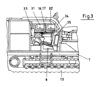
Figure 3 again illustrates how well the the electric unit 9 designed as a
compact station 10 can be operated from the control station 6. From the
driver's
seat 33 it is not only possible to control and operate the operating equipment
with
the reference numeral 35, but also, in particular, the two monitors 31, 32
here as
well as all other devices required for controlling the selective cutting
machine and
for its safety. To this effect the control station 6 is integrated into the
machine
frame 3 of the selective cutting machine 1 in that it is arranged on a console
7 on
the longitudinal side of the machine frame 3 immediately above the chassis 13.
Finally Figure 4 shows a compact station 10 according to the invention for
receiving the relevant electrical equipment. All modules are arranged in the
housing 42 on an assembly panel, which cannot be seen here. These can be slid
in over a rail system into the compact station 10 in order to achieve rapid
exchange of the modules. The compact station includes a power module,
equipment for lighting and control voltages, control computer, safety
controller and
a power supply. With its dimensions of, for example, 40 cm in height, 100 cm
in
width and 200 cm in depth, such a compact station 10 is particularly small and
low
so it can be integrated well into the machine frame of a selective cutting
machine.
AMENDED SHEET