Note: Descriptions are shown in the official language in which they were submitted.
CA 02780762 2012-06-11
- 1 -
SETTING TOOL FOR EXPANDABLE LINER HANGER AND
ASSOCIATED malums
TECHNICAL FIELD
The present invention relates generally to equipment
utilized and operations performed in conjunction with a
subterranean well and, in an embodiment described herein,
more particularly provides a setting tool for an expandable
liner hanger and associated methods.
BACKGROUND
Expandable liner hangers are generally used to secure
a liner within a previously set casing or liner string.
These types of liner hangers are typically set by expanding
the liner hangers radially outward into gripping and
sealing contact with the previous casing or liner string.
,
Many such liner hangers are expanded by use of hydraulic
pressure to drive an expanding cone or wedge through the
liner hanger, but other methods may be used (such as
mechanical swaging, explosive expansion, memory metal
expansion, swellable material expansion, electromagnetic
force-driven expansion, etc.).
The expansion process is typically performed by means
of a setting tool used to convey the liner hanger and
attached liner into a wellbore. The setting tool is
interconnected between a work string (e.g., a tubular
string made up of drill pipe or other segmented or
continuous tubular elements) and the liner hanger.
If the liner hanger is expanded using hydraulic
pressure, then the setting tool is generally used to
control the communication of fluid pressure, and flow to
CA 02780762 2012-06-11
- 2 -
and from various portions of the liner hanger expansion
mechanism, and between the work string and the liner. The
setting tool may also be used to control when and how the
work string is released from the liner hanger, for example,
after expansion of the liner hanger, in emergency
situations, or after an unsuccessful setting of the liner
hanger.
It is desirable to minimize a wall thickness of the
setting tool and liner hanger assembly, so that equivalent
circulating density (ECD) is reduced, and so that the
assembly can be conveyed rapidly into the well.
It will, therefore, be appreciated that improvements
are needed in the art of expandable liner hanger setting
tools and associated methods of installing expandable liner
hangers. These improvements can include improvements to
reduce ECD during running in, to increase operational
efficiency, convenience of assembly and operation, improved
functionality, etc. whether or not discussed above.
SUMMARY
In carrying out the principles of the present
invention, a setting tool and associated methods are
provided which solve at least one problem in the art. One
example is described below in which the setting tool uses a
pressure balanced expansion cone to expand the liner
hanger. Another example is described below in which there
is no polished bore receptacle (PBR) of the liner hanger
which extends upwardly from the expansion cone.
In one aspect, a method of setting an expandable liner
hanger in a subterranean well is provided. The method
includes the steps of: releasably securing a liner hanger
setting tool to the liner hanger, the setting tool
CA 02780762 2012-06-11
- 3 -
including an expansion cone for displacing through the
liner hanger; and conveying the setting tool and liner
hanger into the well on a generally tubular work string.
No portion of the liner hanger extends longitudinally
between the expansion cone and the work string in the
conveying step.
In another aspect, a liner hanger setting tool for
setting an expandable liner hanger in a subterranean well
is provided. The setting tool includes an expansion cone,
which is displaceable through the liner hanger to expand
the liner hanger; at least one piston positioned on one
side of the expansion cone; and an anchoring device for
releasably securing the setting tool to the liner hanger,
the anchoring device being positioned on an opposite side
of the expansion cone from the piston. The expansion cone
is pressure balanced between its two sides when the
expansion cone is displaced through the liner hanger.
These and other features, advantages, benefits and
objects of the present invention will become apparent to
one of ordinary skill in the art upon careful consideration
of the detailed description of representative embodiments
of the invention hereinbelow and the accompanying drawings,
in which similar elements are indicated in the various
figures using the same reference numbers.
BRIEF DESCRIPTION OF THE DRAWINGS
FIG. 1 is a schematic partially cross-sectional view
of a liner hanger setting system and associated methods
which embody principles of the present invention;
FIGS. 2A-K are cross-sectional views of successive
axial sections of a liner hanger setting tool and
expandable liner hanger which may be used in the system and
CA 02780762 2012-06-11
- 4 -
method of FIG. 1, the setting tool and liner hanger being
illustrated in a run-in configuration;
FIGS. 3A & B are cross-sectional views of a portion of
the setting tool after a compressive force has been applied
from a work string to the setting tool in a release
procedure; and
FIGS. 4A-K are cross-sectional views of the setting
tool at the conclusion of a liner hanger expansion
procedure.
DETAILED DESCRIPTION
It is to be understood that the various embodiments of
the present invention described herein may be utilized in
various orientations, such as inclined, inverted,
horizontal, vertical, etc., and in various configurations,
without departing from the principles of the present
invention. The embodiments are described merely as
examples of useful applications of the principles of the
invention, which is not limited to any specific details of
these embodiments.
In the following description of the representative
embodiments of the invention, directional terms, such as
"above", "below", "upper", "lower", etc., are used for
convenience in referring to the accompanying drawings. In
general, "above", "upper", "upward" and similar terms refer
to a direction toward the earth's surface along a wellbore,
and "below", "lower", "downward" and similar terms refer to
a direction away from the earth's surface along the
wellbore.
Representatively illustrated in FIG. 1 is a liner
hanger setting system 10 and associated method which embody
CA 02780762 2012-06-11
- 5 -
principles of the present invention. In this system 10, a
casing string 12 has been installed and cemented within a
wellbore 14. It is now desired to install a liner 16
extending outwardly from a lower end of the casing string
12, in order to further line the wellbore 14 at greater
depths.
Note that, in this specification, the terms "liner"
and "casing" are used interchangeably to describe tubular
materials which are used to form protective linings in
wellbores. Liners and casings may be made from any
material (such as metals, plastics, composites, etc.), may
be expanded or unexpanded as part of an installation
procedure, and may be segmented or continuous. It is not
necessary for a liner or casing to be cemented in a
wellbore. Any type of liner or casing may be used in
keeping with the principles of the present invention.
As depicted in FIG. 1, an expandable liner hanger 18
is used to seal and secure an upper end of the liner 16
near a lower end of the casing string 12. Alternatively,
the liner hanger 18 could be used to seal and secure the
upper end of the liner 16 above a window (not shown in FIG.
1) formed through a sidewall of the casing string 12, with
the liner extending outwardly through the window into a
branch or lateral wellbore. Thus, it will be appreciated
that many different configurations and relative positions
of the casing string 12 and liner 16 are possible in
keeping with the principles of the invention.
A setting tool 20 is connected between the liner
hanger 18 and a work string 22. The work string 22 is used
to convey the setting tool 20, liner hanger 18 and liner 16
into the wellbore 14, conduct fluid pressure and flow,
CA 02780762 2012-06-11
- 6 -
transmit torque, tensile and compressive force, etc. The
setting tool 20 is used to facilitate conveyance and
installation of the liner 16 and liner hanger 18, in part
by using the torque, tensile and compressive forces, fluid
pressure and flow, etc. delivered by the work string 22.
At this point, it should be specifically understood
that the principles of the invention are not to be limited
in any way to the details of the system 10 and associated
methods described herein. Instead, it should be clearly
understood that the system 10, methods, and particular
elements thereof (such as the setting tool 20, liner hanger
18, liner 16, etc.) are only examples of a wide variety of
configurations, alternatives, etc. which may incorporate
the principles of the invention.
Referring additionally now to FIGS. 2A-K, detailed
cross-sectional views of successive axial portions of the
liner hanger 18 and setting tool 20 are representatively
illustrated. FIGS. 2A-K depict a specific configuration of
one embodiment of the liner hanger 18 and setting tool 20,
but many other configurations and embodiments are possible
without departing from the principles of the invention.
The liner hanger 18 and setting tool 20 are shown in
FIGS. 2A-K in the configuration in which they are conveyed
into the wellbore 14. The work string 22 is attached to
the setting tool 20 at an upper threaded connection 24, and
the liner 16 is attached to the liner hanger 18 at a lower
threaded connection 26 when the overall assembly is
conveyed into the wellbore 14.
The setting tool 20 is releasably secured to the liner
hanger 18 by means of an anchoring device 28 (see FIG. 2K)
which includes collets 30 engaged with recesses 32 formed
CA 02780762 2012-06-11
- 7 -
in a setting sleeve 34 of the liner hanger. When
operatively engaged with the recesses 32 and outwardly
supported by a support sleeve 36, the collets 30 permit
transmission of torque and axial force between the setting
tool 20 and the liner hanger 18.
The support sleeve 36 is retained in position
outwardly supporting the collets 30 by shear pins 38.
However, if sufficient pressure is applied to an internal
flow passage 40 of the setting tool 20, a piston area
between seals 42 will cause the shear pins 38 to shear, and
the support sleeve 36 will displace downwardly, thereby
unsupporting the collets 30 and allowing them to disengage
from the recesses 32.
In addition, the anchoring device 28 can be released
by downwardly displacing a generally tubular inner mandrel
44 assembly through which the flow passage 40 extends. The
threaded connection 24 is at an upper end of the inner
mandrel 44 assembly (see FIG. 2A).
A set of shear screws 46 releasably retain the inner
mandrel 44 in position relative to an outer housing
assembly 48 of the setting tool 20. If sufficient downward
force is applied to the inner mandrel 44 (such as, by
slacking off on the work string 22 after the liner hanger
18 has been set, or after tagging the bottom of the
wellbore 14 or other obstruction with the liner 16), the
shear screws 46 will shear and permit downward displacement
of the inner mandrel relative to the outer housing assembly
48.
In FIGS. 3A & B, portions of the setting tool 20 are
representatively illustrated after the inner mandrel 44 has
displaced downward relative to the outer housing assembly
CA 02780762 2012-06-11
-8-
48. In FIG. 3A, the sheared screws 46 can be seen, along
with the manner in which the inner mandrel 44 is downwardly
displaced.
In FIG. 33, it may be seen that the collets 30 are no
longer outwardly supported by the support sleeve 36. The
collets 30 can now be released from the recesses 32 by
raising the inner mandrel 44 (i.e., by picking up on the
work string 22). Locking dogs 50 prevent the support
sleeve 36 from again supporting the collets 30 as the inner
mandrel 44 is raised.
Note that the setting tool 20 can be released from the
liner hanger 18 at any time. For example, the anchoring
device 28 would typically be released after the liner
hanger 18 is set in the casing string 12, or the anchoring
device could be released as a contingency procedure in the
event that the liner 16 gets stuck in the wellbore 14.
Returning to FIGS. 2A-K, the setting tool 20 is
actuated to set the liner hanger 18 by applying increased
pressure to the flow passage 40 (via the interior of the
work string 22) to thereby increase a pressure differential
from the flow passage to an exterior of the setting tool.
The exterior of the setting tool 20 corresponds to an
annulus 52 between the wellbore 14 (or the interior of the
casing string 12) and the work string 22, setting tool 20,
liner hanger 18 and liner 16.
At a certain predetermined pressure differential from
the flow passage 40 to the annulus 52, a shear pin 58
retaining a valve sleeve 54 will shear, the valve sleeve
will displace upward, and a flapper valve 56 will close.
This closing of the flapper valve 56 will isolate an upper
portion 40a of the flow passage 40 from a lower portion 40b
CA 02780762 2012-06-11
- 9 -
of the flow passage (see FIG. 4H). The closed flapper
valve 56 will, however, allow pressure to be equalized
between the flow passage portions 40a, 40b when the
increased pressure applied to the flow passage 40 via the
work string 22 is released.
Pressure in the upper flow passage portion 40a is then
increased again (such as, by applying increased pressure to
the work string 22) to apply a pressure differential across
three pistons 60 interconnected in the outer housing
assembly 48 (see FIGS. 2C, D & F). An upper side of each
piston 60 is exposed to pressure in the flow passage 40 via
ports 62 in the inner mandrel 44, and a lower side of each
piston is exposed to pressure in the annulus 52 via ports
64 in the outer housing assembly 48.
If the valve 56 were to leak when pressure is
increased in the upper flow passage portion 40a, the
increased pressure could possibly be applied via the lower
flow passage portion 40b to the interior of the liner
hanger 18. This could damage the liner hanger 18.
To prevent this from occurring, a venting device 70 is
provided below the valve 56. The venting device 70 will
vent the lower flow passage portion 40b to the annulus 52
(via one of the ports 64) if a pressure differential across
the venting device reaches a predetermined limit. The
venting device 70 is representatively illustrated in the
drawings as a rupture disk, but other types of venting
devices, pressure relief devices, etc. may be used, if
desired.
If the valve 56 does leak, a ball or other plug (not
shown) can be dropped or circulated through the work string
22 to sealingly engage a seat 72 in the inner mandrel 44.
CA 02780762 2012-06-11
- 10 -
This will effectively isolate the upper flow passage
portion 40a from the lower flow passage portion 40b.
An expansion cone 66 is positioned at a lower end of
the outer housing assembly 48. The expansion cone 66 has a
lower frusto-conical surface 68 formed thereon which is
driven through the interior of the liner hanger 18 to
outwardly expand the liner hanger. The term "expansion
cone" as used herein is intended to encompass equivalent
structures which may be known to those skilled in the art
as wedges or swages, whether or not those structures
include conical surfaces.
Note that only a small upper portion of the liner
hanger 18 overlaps the expansion cone 66. This
configuration beneficially reduces the required outer
diameter of the setting tool 20 and liner hanger 18
assembly, which thereby reduces the equivalent circulating
density while circulating through the assembly, and enables
the assembly to be conveyed more rapidly into the well.
The differential pressure across the pistons 60 causes
each of the pistons to exert a downwardly biasing force on
the expansion cone 66 via the remainder of the outer
housing assembly 48. These combined biasing forces drive
the expansion cone 66 downwardly through the interior of
the liner hanger 18, thereby expanding the liner hanger.
Although three of the pistons 60 are illustrated in
the drawings and described above, any greater or lesser
number of pistons may be used. If greater biasing force is
needed for a particular setting tool/liner hanger
configuration, then more pistons 60 may be provided.
Greater biasing force may also be obtained by increasing a
piston area of each of the pistons 60.
CA 02780762 2012-06-11
- 11 -
The setting tool 20 and liner hanger 18 are
representatively illustrated in FIGS. 4A-K after the liner
hanger has been expanded. Note that the expansion cone 66
has been displaced downward through the liner hanger 18 to
thereby expand the liner hanger radially outward.
Note that, when the outer housing assembly 48 has
displaced downward a predetermined distance relative to the
inner mandrel 44, a closure 76 will be contacted and
displaced by the inner mandrel to thereby open a port 74
and provide fluid communication between the exterior of the
setting tool 20 and an internal chamber 78 exposed to an
upper side of one of the pistons 60 (see FIG. 4D). Since
the chamber 78 is also in communication with the upper flow
passage portion 40a above the valve 56 (via one of the
ports 62), this operates to equalize pressure between the
flow passage 40 and the annulus 52 (or at least provide a
noticeable pressure drop at the surface to indicate that
the setting operation is successfully concluded). The port
74 may alternatively be placed in fluid communication with
the chamber 78 due to the port displacing past a seal 80
carried on the inner mandrel 44 assembly.
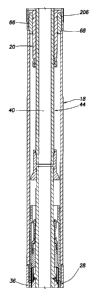
With the liner hanger 18 expanded as depicted in FIGS.
4A-K, external seals 206 on the liner hanger 18 would now
sealingly and grippingly engage the interior of the casing
string 12 in the system of FIG. 1. The inner mandrel 44
can now be displaced downward (i.e., by slacking off on the
work string 22) to release the anchoring device 28 as
described above. The setting tool 20 can then be retrieved
from the well.
It may now be fully appreciated that the system 10,
setting tool 20 and associated methods described above
CA 02780762 2012-06-11
- 12 -
provide significant improvements in the art of setting
expandable liner hangers. One benefit is that an external
diameter of the setting tool 20 and liner hanger 18 may be
reduced. This, in turn, reduces equivalent circulating
density during circulation, and allows more rapid
installation of the setting tool 20 and liner hanger 18 in
a well.
The above description, in particular, provides a
method of setting an expandable liner hanger 18 in a
subterranean well, with the method including the steps of:
releasably securing a liner hanger setting tool 20 to the
liner hanger 18, the setting tool including an expansion
cone 66 for displacing through the liner hanger; and
conveying the setting tool and liner hanger into the well
on a generally tubular work string 22, wherein no portion
of the liner hanger 18 extends longitudinally between the
expansion cone 66 and the work string 22.
The method may also include the step of displacing the
expansion cone 66 through the liner hanger 18, with the
expansion cone being pressure balanced during the
displacing step.
The step of releasably securing the setting tool 20 to
the liner hanger 18 may include positioning the expansion
cone 66 between an anchoring device 28 and the work string
22. The releasably securing step may include positioning
the expansion cone 66 between an anchoring device 28 and at
least one piston 60.
The method may include the piston 60 displacing the
expansion cone 66 through the liner hanger 18 in response
to a pressure differential between an exterior 52 of the
CA 02780762 2012-06-11
- 13 -
setting tool 20 and an internal flow passage 40 of the
setting tool.
The method may include the step of opening a port 74
providing fluid communication between the exterior of the
setting tool 20 and an internal chamber 78 of the setting
tool in response to displacement of the piston 60 a
predetermined distance.
The setting tool 20 in the method may include multiple
pistons 60, and each of the pistons may apply a respective
biasing force to the expansion cone 66 in response to the
pressure differential. The pistons 60 may be annular
shaped and circumscribe a generally tubular inner mandrel
44 of the setting tool 20, and the method may include the
step of displacing the inner mandrel 44 to release the
anchoring device 28 from the liner hanger 18.
Also provided by the above description is a liner
hanger setting tool 20 for setting an expandable liner
hanger 18 in a subterranean well. The setting tool 20 may
include an expansion cone 66, which is displaceable through
the liner hanger to expand the liner hanger; at least one
piston 60 positioned on a first side of the expansion cone
66; an anchoring device 28 for releasably securing the
setting tool 20 to the liner hanger 18, the anchoring
device being positioned on a second side of the expansion
cone 66 opposite the first side; and the expansion cone 66
being pressure balanced between its first and second sides
when the expansion cone is displaced through the liner
hanger 18.
The setting tool 20 may also include a port 74 which
is openable to provide fluid communication between an
exterior of the setting tool and an inner chamber 78 of the
CA 02780762 2012-06-11
- 14 -
setting tool in response to displacement of the piston 60 a
predetermined distance.
At least a portion of the expansion cone 66 may be
positioned longitudinally between the liner hanger 18 and
the piston 60 when the liner hanger is releasably secured
to the setting tool 20.
The piston 60 may be responsive to a pressure
differential between an inner flow passage 40 and an
exterior of the setting tool 20 to displace the expansion
cone 66 through the liner hanger 18.
The setting tool 20 may include a valve 56 which is
selectively closable to isolate a first portion of the flow
passage 40a from a second portion of the flow passage 40b
in fluid communication with an interior of the liner hanger
18, and a venting device 70 which provides fluid
communication between the flow passage second portion 40b
and the exterior of the setting tool 20 in response to a
predetermined pressure differential between the flow
passage second portion and the exterior of the setting
tool.
The setting tool 20 may include multiple pistons 60,
each of the pistons being operative to apply a respective
biasing force to the expansion cone 66 in response to the
pressure differential. The pistons 60 may be annular
shaped and circumscribe a generally tubular inner mandrel
44 of the setting tool 20.
Of course, a person skilled in the art would, upon a
careful consideration of the above description of
representative embodiments of the invention, readily
appreciate that many modifications, additions,
substitutions, deletions, and other changes may be made to
CA 02780762 2013-08-19
- 15 -
these specific embodiments, and such changes are within the scope of the
principles
of the present invention. Accordingly, the foregoing detailed description is
to be
clearly understood as being given by way of illustration and example only, the
scope
of the present invention being limited solely by the appended claims.