Note: Descriptions are shown in the official language in which they were submitted.
CA 02780854 2012-05-14
WO 2011/080384 PCT/F12010/051006
Disc tumbler cylinder lock and key combination
Technical field
This invention relates to a disc tumbler cylinder lock and key combination. In
par-
ticular, the invention relates to a combination, the disc tumbler cylinder
lock of which
is provided with a rotation limiter.
Background art
In disc tumbler cylinder locks, tumbler discs are used to resolve a key-
specific
code and open the lock. Inserting a key into a disc tumbler cylinder lock does
not yet
cause the code to be resolved, rather it is the turning of the key that causes
turning of
the tumbler discs according to the grooves of the key and thus resolution of
the key
code.
It has been observed that if the key is, for some reason, not fully inserted
into a
disc tumbler cylinder lock, then turns of the key can, in this case, cause a
very slight
turning of the tumbler discs away from their common standard position. The
standard
position means that the key can be inserted into the lock. If some of the
tumbler discs
have turned a tiny bit from the standard position, then inserting the key into
the lock
does not go smoothly, it will instead be experienced as difficult or
impossible. The key
will have to be turned several times from side to side in order to get the key
fully into
the cylinder lock. To prevent this, disc tumbler cylinder locks are often
provided with a
rotation limiter.
A rotation limiter is a mechanism, which prevents a key from turning in a disc
tum-
bler cylinder lock, if the key is not fully inserted into the cylinder. The
rotation limiter
allows a key in a cylinder lock to be turned, when the key is fully inserted
into the cyl-
inder. Patent publication FI 108308 presents a known rotation limiter of a
disc tumbler
cylinder lock. The rotation limiter comprises a frame and a casing. The casing
is con-
nected to the inner cylinder of the disc tumbler cylinder lock. In the centre
of the
frame is a key profile opening, through which the key can be inserted into the
cylinder
CA 02780854 2012-05-14
WO 2011/080384 PCT/F12010/051006
2
lock. On both sides of the key profile opening is a limiting mechanism in the
same
line. The limiting mechanism is made up of a spring and balls on both sides of
the
spring. If the key is not fully inserted into the cylinder lock, the surface
of the shaft of
the key keeps the balls of the limiting mechanism so close to each other that,
if an
attempt is made to turn the key, the ball on the casing side is unable to move
away
from the hollow of the casing. Because the casing is connected to the inner
cylinder,
which is not able to turn until the key code is fully resolved, a key that is
incompletely
inserted into the cylinder lock is not able to turn.
The key has counter surfaces for the balls of the limiting mechanism. The
counter
surfaces are recesses in the surface of the key. When the key is in the
correct place
in the key cylinder, the ball of the limiting mechanism on the key side is in
the recess
of the key, and as the key is turned, the ball on the casing side is able to
move away
from the hollow of the casing. Thus, the key can be turned in order to move
the tum-
bler discs into the correct position for opening the lock. In this case, the
inner cylinder
is able to turn as turning of the key is continued.
The rotation limiter makes the disc tumbler cylinder lock more functionally
reliable.
However, it is able to rotate in the cylinder lock, when a key is not inserted
into the
lock. This rotation facilitates the possible picking of the lock.
Brief description of the invention
The object of the invention is a disc tumbler cylinder lock, the rotation
limiter of
which is not able to rotate, when a key is not in the cylinder lock. The
object is
achieved in the manner described in the independent claim. The dependent
claims
describe various embodiments of the invention.
The inventive solution relates to a disc tumbler cylinder lock and key
combination.
The disc tumbler cylinder lock of the combination comprises rotation limiting
means of
the key, and the key comprises guidance surfaces for the rotation limiting
means. The
rotation limiting means comprise a frame, which has a key profile opening and
a cas-
ing, which at least partially surrounds the frame. The frame comprises a
limiting
mechanism and a locking mechanism, which are disposed in a line such that the
lim-
CA 02780854 2012-05-14
WO 2011/080384 PCT/F12010/051006
3
iting mechanism is on the other side of the key profile opening and the
locking
mechanism is on the opposite side of the key profile opening.
The locking mechanism comprises a locking pin directed along said line, which
comprises, at the end on the casing side, a projection that is transverse in
relation to
the axis of the locking pin. The projection is arranged, in cooperation with
the casing,
to prevent the frame from turning, when the key is not in the lock or fully
inserted into
the lock.
The key of the combination comprises a through hole, in which hole a moving
ele-
ment is disposed. The element is arranged to move in the hole such that it is
pre-
vented from moving entirely away from the hole. The surfaces of the moving
element,
which are visible from the through hole, form said guidance surfaces.
When the key is in the lock for the purpose of opening the lock, the through
hole
and the moving element are in the same line with the limiting mechanism and
the
locking mechanism. The limiting mechanism is arranged to push the moving
element
out from the hole onto the opposite side of the key profile opening and thus
to allow
the key to turn. The locking mechanism is arranged, in response to the pushing
of the
moving element, to release the barrier formed by the cooperation of the casing
and
the projection of the locking pin. Thus, the interacting functionalities of
the limiting
mechanism, the element of the key and the locking mechanism provide the
situation
that the rotation limiter is not able to turn, when the key is incompletely
inserted into
the disc tumbler cylinder lock or it is not in the cylinder at all. Thus, a
key inserted in-
completely into the lock or an incorrect key inserted into the lock is not
able to turn.
Additionally, the duplication of a key is more difficult, when there is a
moving ele-
ment in the key. This complicates the production of illegal copies.
List of figures
In the following, the invention is described in greater detail with reference
to the ac-
companying figures, in which
CA 02780854 2012-05-14
WO 2011/080384 PCT/F12010/051006
4
Fig. 1 shows an example of a disc tumbler cylinder lock according to the inven-
tion,
Fig. 2 shows an example of a rotation limiter and key according to the
invention,
Fig. 3 shows the example in Fig. 2 with the key inserted into the rotation
limiter,
Fig. 4 shows the example in Fig. 3, when the key is turned,
Fig. 5 shows a sectional view of the rotation limiter of the example in Fig.
2,
Fig. 6 shows an exploded view of the rotation limiter of the example in Fig.
2,
Fig. 7 shows another sectional view of the rotation limiter of the example in
Fig. 2,
and
Fig. 8 shows a third sectional view of the rotation limiter and key of the
example
in Fig. 2.
Description
Fig. 1 shows an example of a disc tumbler cylinder lock according to the
invention.
The cylinder lock comprises an outer cylinder 2A, into which is inserted an
inner cyl-
inder 2 with its tumbler discs. The disc tumbler cylinder lock comprises a
rotation lim-
iter 3, which has a key profile opening 4.
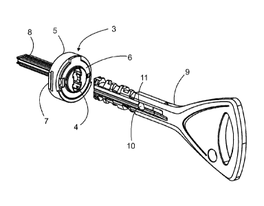
Fig. 2 shows an example of a rotation limiter and key according to the
invention.
The key 9 comprises a through hole 11, in which a moving element 10 is
disposed.
The edges of the through hole are machined, for example by upsetting, such
that the
moving element is not able to completely move away from the hole. A preferred
em-
bodiment of the moving element is a ball. The moving element can also be, for
ex-
ample, a pin. In this case, remaining of the moving element in the through
hole can
also be arranged by other means than by machining the edges. Those surfaces of
the moving element, which are visible from the through hole, are guidance
surfaces.
The guidance surfaces are seated against the locking mechanism and the
limiting
mechanism of the rotation limiting means, when the key is fully inserted into
the disc
tumbler cylinder lock.
CA 02780854 2012-05-14
WO 2011/080384 PCT/F12010/051006
The rotation limiter (rotation limiting means) is made up of a casing 5 and a
frame
6. The frame comprises a key profile opening 4, a limiting mechanism 24 (see
Fig. 6)
and a locking mechanism 25. The limiting mechanism and the locking mechanism
are disposed in a line such that the limiting mechanism is on the other side
of the key
5 profile opening 4 and the locking mechanism is on the opposite side of the
key profile
opening. The structure and function of the limiting mechanism 24 and the
locking
mechanism 25 are shown in Figs. 3 - 8. The frame 6 and the casing 5 are
connected
to each other through the locking mechanism such that the frame is not able to
turn in
relation to the casing other than when the key 9 is fully inserted into the
disc tumbler
cylinder lock. The casing at least partially surrounds the frame. The casing
has at-
tachment surfaces 7, with which the rotation limiter can be connected to the
inner cyl-
inder 2 of the cylinder lock. The attachment surfaces of the casing can be
imple-
mented in several different manners. Fig. 2 shows one manner, and FI 108308
shows another manner. One preferred embodiment of the rotation limiter
comprises a
guidance element 8 connected to the rotation limiter.
The structure of the rotation limiter is shown in greater detail in Figs. 5
and 6. The
function and structure are shown in Figs. 3, 4, 7 and 8.
Fig. 5 shows a sectional view of the rotation limiter of the example in Fig.
2. Fig. 6
shows an exploded view of the rotation limiter of the example in Fig. 2. The
frame 6
of the rotation limiter can be formed from one or several parts. The frame has
borings
23, in which the limiting mechanism 24 and the locking mechanism 25 are
disposed.
The limiting mechanism 24 comprises in a known manner two balls 12, 14 and a
spring 13 between the balls. One of the balls 14 lies against the casing 5.
The casing
has a hollow 28 for the ball. If the key is not in the cylinder lock or it is
fully inserted
into the cylinder lock, then the ball on the casing side is able to move away
from the
hollow 28 of the casing as the key is turned or otherwise as the rotation
limiter is
turned (if there were no locking mechanism). The limiting mechanism and the
locking
mechanism are in the same line on different sides of the key profile opening
4.
The locking mechanism 25 comprises a locking pin 15 directed along said line,
which locking pin comprises, at the end of the casing side, a projection 21,
which is
transverse in relation to the axis of the locking pin. The projection is
arranged, in co-
CA 02780854 2012-05-14
WO 2011/080384 PCT/F12010/051006
6
operation with the casing, to prevent the frame from turning, when the key is
not in
the lock or fully inserted into the lock.
The frame has a cut 27 at the site of the projection 21 of the locking pin to
allow
the movement of the locking pin in the direction of the line. The casing has a
groove
19 and a cut 18. The cut 18 is at the site of the locking pin to allow the
moving of the
projection 21 of the locking pin to the site of the groove 19. At least one
surface of the
cut is a barrier surface 20. The barrier surface and projection work in
cooperation to
prevent the frame from turning, when the projection is at the site of the
barrier sur-
face. The gap between the barrier surface and the projection is shown as
relatively
large in Fig. 5. It is obvious that this gap can be smaller.
The basic shape of the casing 5 is a ring. The casing comprises an indented
collar
29, i.e. the collar is a projection on the inner surface of the ring. Said
groove and cut
are located in the collar. The groove (as well as the collar) are at least at
the site of
the turning sector of the key. By turning sector is meant the turning area of
the key,
where the key code is resolved in a cylinder lock. From a production
viewpoint, a pre-
ferred embodiment is that the groove 19 and collar 29 form a complete circle
on the
inner surface of the casing. The frame 6 is placed into the casing 5 such that
the cas-
ing at least partially covers the edge area of the frame. From the figures, it
can be
stated that the frame and casing are mainly circular in shape.
The locking mechanism 25 comprises a flexible element 16 to push the locking
pin
toward the key profile opening 4. The flexible element is placed between the
casing 5
and the locking pin. It is preferred that the locking pin has a recess 22, in
which the
flexible element can be placed. This facilitates assembly of the rotation
limiter. It is
also preferred that between the flexible element 16 and the casing is located
a ball
17. The ball makes the use of the rotation limiter more pleasant and
functionally reli-
able in comparison to a locking mechanism without a ball.
A spring structure is a preferred embodiment for the flexible element. In the
em-
bodiment shown in the figures, the projection 21 of the locking pin is a
locking plate.
The projection can also have some other form, for example that of a pin, which
is di-
rected toward the collar of the casing.
CA 02780854 2012-05-14
WO 2011/080384 PCT/F12010/051006
7
As was stated above, in the through hole 11 of the key 9 is disposed a moving
element 10, which is arranged to move in the hole. When the key is in the lock
for the
purpose of opening the lock, or more specifically in the cylinder lock, the
through hole
11 and the moving element 10 are in the same line with the limiting mechanism
24
and the locking mechanism 25. Fig. 7 shows a sectional view of the rotation
limiter,
when the key is not in the cylinder lock. Figs. 3 and 8 show sectional views,
when the
key is in the cylinder lock (and thus also in the rotation limiter). In Fig.
8, the key is
slightly turned.
When the key is not in the cylinder lock, the projection 21 of the locking pin
15 is
not at the site of the groove 19. This also holds true, when the key is only
incom-
pletely inserted into the cylinder lock. The locking pin 15 is arranged in the
frame of
the rotation limiter such that that it is not able to be pushed into the key
profile open-
ing 4, as it would otherwise prevent a key from being inserted into the
cylinder lock.
The head 26 of the locking pin and the boring 23 of the frame at the end of
the key
profile opening could have been formed as narrower than the other part of the
locking
pin and the boring.
When the key is in the lock, the limiting mechanism 24 is arranged to push the
moving element 10 out of the hole 11 onto the opposite side of the key profile
open-
ing 4. The ball 12 of the limiting mechanism on the key profile opening side
pushes
the moving element 10. The moving element, for its part, moves toward the
locking
pin 15, which moves in the direction of the casing against the flexible
element. The
moving of the locking pin in the direction of the casing moves the projection
21 of the
locking pin to the site of the groove 19 of the casing. Fig. 8 shows this
situation.
When the projection is at the site of the groove, the key can be turned. In
Fig. 8, the
key 9 is slightly turned, wherein the ball 14 of the limiting mechanism on the
casing
side has risen up away from the hollow 28 of the casing. Fig. 4 also
illustrates, how a
projection of the locking pin that has moved to the site of the groove enables
turning
of the key. When the key is removed from the cylinder lock, the flexible
elements of
the limiting mechanism and the locking mechanism return the rotation limiter
to the
state described above, in which the key is not in the cylinder.
CA 02780854 2012-05-14
WO 2011/080384 PCT/F12010/051006
8
The rotation limiter is therefore not able to turn (at the most only slightly
due to tol-
erances of the parts), when the key is not in the cylinder lock. This makes
possible
attempts to pick open the cylinder lock (and lock) more difficult, as the
rotation limiter
thus forms an additional barrier and also limits the use of space.
It is obvious that the invention is not limited to the examples mentioned in
this text
only, rather the invention can be implemented by a plurality of various
embodiments
within the scope of the presented claims.