Note: Descriptions are shown in the official language in which they were submitted.
4
WO 2011/059678 PCT/US2010/053851
ELECTRIC ACTUATORS HAVING INTERNAL LOAD APPARATUS
FIELD OF THE DISCLOSURE
[0001] The present disclosure relates generally to electric actuators and,
more
particularly, to electric actuators having internal load apparatus.
BACKGROUND
[0002] Control valves (e.g., sliding stem valves) are commonly used in
process control systems to control the flow of process fluids. A control valve
typically includes an actuator (e.g., an electric actuator, a hydraulic
actuator, etc.) that
automates operation of the control valve. Sliding stem valves such as gate,
globe,
diaphragm, pinch, and angle valves typically have a valve stem (e.g., a
sliding stem)
that drives a fluid flow control member (e.g., a valve plug) between an open
position
and a closed position.
[0003] Electric actuators often employ a motor operatively coupled to a flow
control member via a drive system (e.g., one or more gears). During operation,
when
electric power is supplied to the motor, the electric actuator moves the flow
control
member between a closed position and an open position to regulate fluid
flowing
through a valve. When the valve is closed, the flow control member is
typically
configured to sealingly engage an annular or circumferential seal (e.g., a
valve seat)
disposed within the flow path to prevent the flow of fluid between an inlet
and an
outlet of the valve.
[0004] When the valve is in the closed position and electric power is provided
to the motor, the motor typically provides sufficient seat load to the fluid
flow control
member to ensure that the fluid flow control member is in sealing engagement
with a
valve seat of the valve. When electric power is removed from the motor, the
drive
system (e.g., worm gears) may maintain the position of the fluid flow control
member
relative to the valve seat and prevent substantial movement of the fluid flow
control
member in a reverse or opposite direction (e.g., away from the valve seat).
However,
the drive system may not provide an adequate or sufficient seat load to the
fluid flow
control member to ensure the fluid flow control member is in sealing
engagement
with the valve seat. As a result, fluid may leak through the valve between the
inlet
and the outlet of the valve.
-1-
4
WO 2011/059678 PCT/US2010/053851
SUMMARY
[0005] In one example, an electric actuator includes a housing defining a
cavity to receive a drive system and a drive shaft operatively coupled to the
drive
system. Rotation of the drive system in a first rotational direction causes
the drive
shaft to move in a first rectilinear direction and rotation of the drive
system in a
second rotational direction causes the drive shaft to move in a second
rectilinear
direction opposite the first rectilinear direction. A biasing element is
operatively
coupled to the drive system such that least a portion of the drive system
moves axially
toward the biasing element to deflect the biasing element when the drive shaft
reaches
an end of stroke position to provide a load to the drive shaft when electric
power to
the electric actuator is removed.
[0006] In another example, a load apparatus for use with an electric actuator
includes a drive gear operatively coupled to a drive system of the electric
actuator.
The drive gear rotates in a first direction and a second direction and the
drive gear
moves between a first rectilinear position and a second rectilinear position.
A drive
shaft is operatively coupled to the drive gear such that the drive gear causes
the drive
shaft to move in a first rectilinear direction when the drive gear rotates in
the first
direction and the drive gear causes the drive shaft to move in a second
rectilinear
direction when the drive gear rotates in the second direction. A biasing
element is
disposed between the drive gear and a seating surface such that when the drive
gear
rotates in the first direction and the drive shaft reaches an end of stroke
position in the
first rectilinear direction, the drive gear continues to rotate about the
drive shaft in the
first direction and moves axially relative to the drive shaft from the first
rectilinear
position to the second rectilinear position to deflect the biasing element.
[0007] In yet another example, a load apparatus for use with an electric
actuator includes means for converting rotational motion of a drive system to
rectilinear motion of a drive shaft. The load apparatus also includes means
for
providing a seat load to a fluid flow control member of a fluid valve coupled
to the
drive shaft when the flow control member is in sealing engagement with a valve
seat
of the fluid valve and electric power to a motor is removed. The load
apparatus
further includes means for deflecting that is to move at least a portion of
the means for
converting rotational motion axially relative to the drive shaft toward the
means for
providing a seat load.
-2-
4
WO 2011/059678 PCT/US2010/053851
BRIEF DESCRIPTION OF THE DRAWINGS
[0008] FIG. 1 A illustrates an example control valve assembly described herein
shown in an open position.
[0009] FIG. I B illustrates an enlarged portion of the example actuator of
FIG.
I A.
[0010] FIG. 2 illustrates the example control valve assembly of FIG. IA, but
shown in a closed position, at which a biasing element has not yet been
deflected.
[0011] FIG. 3A illustrates the example control valve assembly of FIGS. 1 and
2 shown in a closed position at which the biasing element has been deflected.
[0012] FIG. 3B illustrates an enlarged portion of the example actuator of FIG.
3A.
[0013] FIGS. 4A and 4B illustrate an enlarged portion of another example
actuator described herein shown in a first position and a second position,
respectively.
[0014] FIGS. 5A-5C illustrate another example control valve assembly
implemented with the example actuator of FIGS. IA, 1 B, 2, 3A, and 3B.
DETAILED DESCRIPTION
[0015] In general, the example electric actuators described herein provide a
seat load to a fluid valve when electric power to a drive motor of the
actuators is
removed. The example electric actuators described herein provide a seat load
without
consuming electric power. More specifically, the example electric actuators
may
include a biasing element disposed within a housing or casing of the actuator
to
provide a seat load to a fluid flow control member of a valve when the fluid
flow
control member is in sealing engagement with a valve seat and the electric
actuator
(e.g., an electric motor) is not receiving electric power. For example, the
biasing
element may be implemented as one or more springs that exert a force to
provide a
seat load to a fluid flow control member (e.g., a valve plug) operatively
coupled to the
electric actuator when the fluid flow control member is sealingly engaged with
the
valve seat (e.g., a closed position) and a power supply source fails to
provide power to
a motor of the electric actuator.
[0016] In contrast, some known electric actuators use a complex combination
of biasing elements, clutches and brake systems that provide a sufficient seat
load
when the electric actuator is in a fail-safe condition. In other words, known
electric
actuators may include a biasing element to move a flow control member of a
valve to
-3-
4
WO 2011/059678 PCT/US2010/053851
a closed position during, for example, a power failure. Thus, if the fluid
valve is in
the open position when a power failure occurs, the biasing element moves the
fluid
flow control member to the closed position. However, these known actuators
often
include complex assemblies. Additionally, some of these known actuation
systems
having fail-safe apparatus typically include a declutchable gear box to enable
operation of the fail-safe apparatus. In other words, a drive assembly must
typically
be operatively decoupled from, for example, a gear transmission to enable
operation
of the fail-safe apparatus. However, declutchable gearboxes are relatively
expensive,
difficult to operate, enlarge the dimensional envelope of a valve and actuator
assembly, and involve complex assemblies within the actuator. Additionally,
such
fail-safe apparatus may not be required and/or desired for some applications,
thereby
unnecessarily increasing the costs of a control valve assembly.
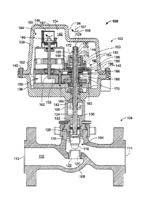
[0017] FIG. IA illustrates an example control valve assembly 100 described
herein. The control valve assembly 100 includes an electric actuator 102
operatively
coupled to a fluid valve 104 via a bonnet 106. The fluid valve 104 includes a
valve
body 108 that defines a fluid flow passageway 110 between an inlet 112 and an
outlet
114. A fluid flow control member 116 (e.g., a valve plug) is disposed within
the fluid
flow passageway 110 and includes a seating surface 118 that sealingly engages
with a
valve seat 120 to control fluid flow through a port area or orifice 122
between the
inlet 112 and the outlet 114. A valve stem 124 is coupled (e.g., threadably
coupled) to
the fluid flow control member 116 at a first end 126 and is operatively
coupled to the
electric actuator 102 at a second end 128. The bonnet 106 is coupled to the
valve
body 108 and includes a bore 130 to slidably receive the valve stem 124. The
bonnet
106 houses a valve packing assembly 132 that provides a seal to oppose the
pressure
of the process fluid flowing through the fluid valve 104 to prevent leakage of
process
fluid past the valve stem 124 and/or protect the environment against the
emission of
hazardous or polluting fluids.
[0018] The actuator 102 includes a housing 134 having a first casing 136
coupled to a second casing 138 via fasteners 140. The first and second casings
136
and 138 of the housing 134 define a cavity 142 to receive a drive system 144.
In this
example, the drive system 144 includes a motor 146 operatively coupled to an
output
shaft or drive shaft 148 via a transmission 150. The transmission 150 converts
rotational motion of the motor 146 to rectilinear motion of the drive shaft
148.
-4-
4
WO 2011/059678 PCT/US2010/053851
[0019] The transmission 150 may be configured to amplify the torque
generated by the motor 146 and transmit the amplified torque to the drive
shaft 148.
The amplified torque transmitted to the drive shaft 148 enables the flow
control
member 116 to engage the valve seat 120 with a greater force and, thus,
provide a
tighter sealing engagement with the valve seat 120 to prevent the flow of
fluid
through the valve body 108 when the flow control member 116 is sealingly
engaged
with the valve seat 120 and electric power is provided to the motor 146. Also,
a
relatively smaller sized motor 146 may be used to drive the flow control
member 116
with a transmission configured to amplify the torque generated by the motor
146. For
example, the amount of torque amplification provided by the transmission 150
can
vary based on the size (e.g., the diameter, number of gear teeth, etc.) of a
gear. In yet
other examples, the motor 146 may be directly coupled to the drive shaft 148.
In such
a direct-drive configuration, the motor 146 directly drives the drive shaft
148 without
any other interposing mechanism or device such as, for example, the
transmission 150
or the like.
[0020] As shown, the transmission 150 includes a gear transmission or
gearbox 152 disposed within the cavity 142 of the housing 134. The motor 146
is
disposed within the cavity 142 of the electric actuator 102 and is coupled to
the
gearbox 152 (e.g., to a housing of the gearbox 152) via, for example, a
fastener and/or
any other suitable fastening mechanism(s). However, in other examples, the
motor
146 may be coupled to the housing 134 of the actuator 102 via fasteners or any
other
suitable fastening mechanism(s). In some examples, the motor 146 may be
coupled to
an interior surface 154 of the housing 134 or to an exterior surface 156 of
the housing
134. The motor 146 may be any motor such as, for example, an alternating
current
(AC) motor, a direct current (DC) motor, a variable frequency motor, a stepper
motor,
a servo motor, or any other suitable motor or drive member. Also, the gearbox
152
may include a plurality of gears (e.g. spur gears), a planetary gear system,
or any
other suitable gear or transmission to convert rotational motion of the motor
146 to
rectilinear motion of the drive shaft 148. As described in greater detail
below, at least
one gear of the transmission 150 translates or moves axially along an axis 157
between a first position and a second position.
[0021] In the illustrated example, the transmission 150 includes an
intermediate gear 158 and a drive gear 160. The intermediate gear 158
operatively
-5-
4
WO 2011/059678 PCT/US2010/053851
couples an output shaft 162 of the motor 146 and the drive gear 160. As shown,
the
drive gear 160 includes a gear engaging portion 164 and a second portion 166
(e.g.,
integrally formed with the gear engaging portion 164) having a recessed
opening 168.
The gear engaging portion 164 includes gear teeth to mesh with or engage gear
teeth
of the intermediate gear 158. Also, the drive gear 160 includes a threaded
aperture or
opening 170 to threadably receive the drive shaft 148.
[0022] As shown, the drive shaft 148 is a screw. More specifically, the drive
shaft 148 comprises a cylindrically-shaped body 172 having an aperture or
opening
174 and an externally threaded portion 176. The opening 174 of the drive shaft
148
receives the second end 128 of the valve stem 124. A flanged nut 178
threadably
couples to a threaded end 180 of the valve stem 124 to capture or retain the
drive shaft
148 between a shoulder 182 of the valve stem 124 and the flanged nut 178. The
externally threaded portion 176 of the drive shaft 148 is threadingly coupled
to the
threaded aperture 170 of the drive gear 160. Although not shown, in other
examples,
the drive shaft 148 may be a gear system, a ball screw system, a leadscrew
system,
and/or any other suitable transmission system to convert rotational motion of
the
motor 146 to rectilinear motion of the valve stem 124.
[0023] A load apparatus or assembly 184 is disposed within the gearbox 152
(e.g., within a housing of the gearbox 152) to provide a seat load to the flow
control
member 116 when the flow control member 116 is in a closed position and
electric
power to the actuator 102 is removed. The load apparatus 184 includes a
biasing
element 186 disposed between the second portion 166 of the drive gear 160 and
a
spring seat or surface 188 of the gearbox 152. The load apparatus 184 may also
include a thrust bearing 190 disposed between the drive gear 160 and the
biasing
element 186. The thrust bearing 190 transmits a load exerted by the biasing
element
186 to the drive gear 160 when the biasing element 186 is deflected and may be
received by the recessed opening 168 of the drive gear 160. In this example,
the
biasing element 186 includes a stack of Belleville springs. The load apparatus
184
may include a spacer 192 disposed between the biasing element 186 and the
surface
188 of the gearbox 152 to adjust the height of the stack of Belleville
springs. In
general, a Belleville spring provides a high loading relative to the travel or
deflection
imparted on the Belleville spring. Thus, as a result, the example load
apparatus 184
may be configured to have a relatively small footprint, thereby reducing the
overall
-6-
4
WO 2011/059678 PCT/US2010/053851
envelope or footprint of the control valve assembly 100. In other examples,
the
biasing element 186 may be a coil spring, spring washers, a wave spring, a
spring
bellow, and/or any other suitable biasing element(s). In yet other examples,
the
biasing element may be integrally formed with a portion of the gear box 152
(e.g., a
housing of the gearbox 152), a portion of the housing 134 and/or any other
suitable
surface of the actuator 102. For example, at least a portion 153 of the
gearbox 152
(e.g., adjacent the drive gear 160) may be made of a flexible material such as
a rubber
material or any other suitable material that provides a biasing force when
deflected.
In such a configuration, the biasing element 186 is not required.
[0024] In FIG. IA, the fluid valve 104 is depicted in an open position 194 and
the biasing element 186 of the load apparatus 184 is in a first or a
substantially non-
deflected condition 196. FIG. 2 illustrates the fluid valve in a closed
position 200, but
showing the biasing element 186 of the load apparatus 184 in a substantially
non-
deflected condition 202. FIG. 3A illustrates the fluid valve 104 in a closed
position
300 and shows the biasing element 186 in a substantially deflected condition
302 to
provide a seat load 304 to the flow control member 116. FIGS. lB and 3B
illustrate
enlarged portions of the load apparatus 184 showing the biasing elements 186
in the
substantially non-deflected condition 194 and the substantially deflected
condition
302, respectively.
[0025] Referring to FIGS. IA, 1B, 2, 3A and 3B, in operation, the electric
actuator 102 is activated to move the flow control member 116 between the open
position 194 of FIG. IA and the closed position 300 of FIG. 3A. The motor 146
drives or rotates the output shaft 162 in a first direction 199 (e.g., a
clockwise
direction) about an axis 197 to move the fluid valve 104 toward the open
position 194
as shown in FIG. IA and a second direction 204 (e.g., a counterclockwise
direction)
opposite the first direction 199 about the axis 197 to move the fluid valve
104 toward
the closed positions 200 and 300 as shown in FIGS. 2 and 3A.
[0026] To move the fluid valve 104 toward the open position 194, electric
power is provided to the motor 146 to rotate the output shaft 162 in the first
direction
199 (FIG. 1 A). The transmission 150 causes the drive gear 160 to rotate in a
first
direction 198 (e.g., a clockwise direction) about the axis 157. Rotation of
the drive
gear 160 in the first direction 198 causes the drive shaft 148 to move in a
rectilinear
motion along the axis 157 in a direction away from the fluid valve 104. More
-7-
4
WO 2011/059678 PCT/US2010/053851
specifically, as the output shaft 162 rotates in the first direction 199, the
intermediate
gear 158 rotates the drive gear 160. In turn, the drive gear 160 rotates about
the
threaded portion 176 of the drive shaft 148 and causes the drive shaft 148 to
move
rectilinearly in a direction along the axis 157 because the intermediate gear
158 and/or
the biasing element 186 help retain or hold the axial position of the drive
gear 160
relative to the axis 157. Additionally, although not shown, a bushing 195 is
coupled
to the gearbox 152 (e.g., disposed within a housing of the gearbox 152 via
press-fit)
having at least one flat (not shown) that engages the drive shaft 148 to
prevent the
drive shaft 148 from rotating or spinning as the drive gear 160 rotates,
thereby
causing the drive shaft 148 to move rectilinearly via the threaded portion 176
as the
drive gear 160 rotates about the threaded portion 176. Because the valve stem
124 is
fixedly coupled to the drive shaft 148 via the flanged nut 178, the drive
shaft 148
causes the valve stem 124 and, thus, the flow control member 116 to move away
from
the valve seat 120 to allow or increase fluid flow through the fluid flow
pathway 110
between the inlet 112 and the outlet 114. As most clearly shown in FIG. 1 B,
when the
fluid valve 104 is in the open position 194, the biasing element 186 is in the
substantially non-deflected condition 196.
[0027] To move the fluid valve 104 toward the closed position 200 as shown
in FIG. 2, electrical power is provided to the motor 146 to cause the output
shaft 162
to rotate in the second direction 204 (e.g., a counterclockwise direction)
about the axis
197. Rotation of the output shaft 162 in the second direction 204 causes the
drive
shaft 148 to move rectilinearly along the axis 157 in a direction toward the
valve body
108. More specifically, as the output shaft 162 rotates in the second
direction 204, the
intermediate gear 158 rotates the drive gear 160 in a second direction 206
about the
axis 157 and the threaded portion 176 of the drive shaft 148, causing the
drive shaft
148 to move rectilinearly in a direction along the axis 157 toward the fluid
valve 104.
Rotation of the drive gear 160 in the second direction 206 about the axis 157
causes
the drive shaft 148 and, thus, the flow control member 116 to move toward the
valve
seat 120 to prevent or restrict fluid flow through the fluid flow pathway 110
between
the inlet 112 and the outlet 114. The biasing element 186 is in the
substantially non-
deflected condition 202 as the drive shaft 148 moves toward the fluid valve
104.
Additionally, although the biasing element 186 is in the substantially non-
deflected
202, a biasing force (e.g., a pre-stress force) provided by the biasing
element 186
-8-
4
WO 2011/059678 PCT/US2010/053851
helps retain the axial position of the drive gear 160 relative to the
intermediate gear
158 and the axis 157.
100281 When the fluid valve 104 is in the closed position 200, the seating
surface 118 of the fluid flow control member 116 sealingly engages the valve
seat 120
to prevent fluid flow through the valve 102. When the fluid flow control
member 116
is in engagement with the valve seat 120, the drive shaft 202 is prevented
from
moving further toward the valve seat 120 because the drive shaft 124 is
rigidly
coupled to the valve stem 124. However, the motor 146 continues to drive the
drive
gear 160 via the intermediate gear 158 causing the drive gear 160 to rotate
about the
threaded portion 176 of the drive shaft 148 while the drive shaft 148 is
substantially
axially stationary relative to the axis 157. In other words, the drive shaft
148 is at an
end of stoke position when the flow control member 116 is sealingly engaged
with the
valve seat 120. As a result, the drive gear 160 moves or translates axially in
a
rectilinear direction toward the upper casing 136 of the housing 134 because
the drive
shaft 148 is prevented from moving (e.g., in a rectilinear motion and/or a
rotational
motion) toward the valve seat 120 when the flow control member 116 is
sealingly
engaged with the valve seat 120. However, in other examples, the end of stroke
position or end of travel may occur when a surface 208 of the drive shaft 148
engages
a portion or surface 210 of the housing 134, the bonnet 106, or any other
surface.
[0029] As the drive gear 160 rotates in the second direction 206 about the
drive shaft 148 when the valve is in the closed position 200, the drive gear
160 moves
or shifts axially along the axis 157 toward the upper casing 136 relative to
the
intermediate gear 158. However, the engaging portion 164 of the drive gear 160
does
not disengage from the intermediate gear 158. In other words, the gear teeth
of the
engaging portion 164 remain engaged with the gear teeth of the intermediate
gear 158
when the drive gear 160 translates axially along the axis 157.
[00301 As most clearly shown in FIG. 3B, the drive gear 160 shifts relative to
the intermediate gear 158 in a rectilinear direction toward the upper casing
136 to
cause the biasing element 186 to deflect or compress to the substantially
deflected
condition 302. In the deflected condition 302, the biasing element 186 exerts
or
provides a force against the drive gear 148. This force is transferred the to
the flow
control member 116 via the thrust bearing 190. In particular, the thrust
bearing 190
transmits the force exerted by the biasing element 186 to the flow control
member 116
-9-
4
WO 2011/059678 PCT/US2010/053851
and allows the drive gear 160 to rotate freely about to the axis 157. Thus,
the drive
gear 160 moves axially along the axis 157 from the position 200 shown in FIG.
2 to
the position 300 shown in FIG. 3A to deflect or compress the biasing element
186
when the fluid valve 104 is in the closed position 200 and the motor 146
continues to
rotate the drive gear 160 in the second direction 206 about the axis 157.
[00311 When in the closed position 200 as shown in FIG. 2, the motor 146
provides a seat load to the fluid flow control member 116 when electric power
is
provided to the motor 146. However, when electric power is removed from the
motor
146, the flow control member 116 may lack adequate or sufficient seat load to
sealingly engage the valve seat 120 when, for example, the fluid valve 104 is
in the
closed position 200 of FIG. 2. Although a backdrive resistance of the motor
146
and/or the transmission 150 maintains the position or prevents rectilinear
motion of
the drive shaft 148 and, thus, the flow control member 116, the backdrive
resistance
of the motor 146 and/or the transmission 150 may not be adequate to maintain
or
provide a seat load to the flow control member 116 when electric power is
removed
from the motor 146. An adequate or sufficient seat load prevents fluid leakage
through the orifice 122 when the flow control member 116 is sealingly engaged
with
the valve seat 120. In other words, an adequate or sufficient seat load
maintains the
fluid flow control member 116 in sealing engagement the valve seat 120 to
substantially prevent fluid flow through the passageway 110 of the fluid valve
104.
Absent such a seat load, fluid may leak past the orifice 122 even when the
sealing
surface 118 of the fluid flow control member 116 engages the valve seat 120.
[0032] When the load apparatus 184 is in the position 302 shown in FIGS. 3A
and 3B, the load apparatus 184 provides the mechanical seat load 304 to
maintain or
keep the fluid flow control member 116 in sealing engagement with the valve
seat 120
if electric power is removed from the motor 146 while the flow control member
116 is
sealingly engaged with the valve seat 120. For example, it may be necessary to
keep
or retain the fluid valve 104 in the closed position 300 to prevent a spill
(e.g., a
chemical spill) during emergency situations, power failures, or if the
electric power
supply to the electric actuator 102 (e.g., the motor 146) is removed or shut
down.
Otherwise, failing to provide an adequate or sufficient seat load to the fluid
flow
control member 116 during, for example, a power outage may cause fluid flow to
pass
through the orifice 122 of the fluid valve 104 between the inlet 112 and the
outlet 114.
-10-
4
WO 2011/059678 PCT/US2010/053851
For example, the pressure of the pressurized fluid at the inlet 112 may
provide a force
against the fluid flow control member 116 (e.g., in a direction toward the
bonnet 106
in the orientation of FIG. 2) to cause the sealing surface 118 of the fluid
flow control
member 116 to move away from the valve seat 120 and allow fluid to flow or
leak
toward the outlet 114 when electric power to the motor 146 is removed.
[0033] Thus, the example load apparatus 184 provides the seat load 304 to the
fluid flow control member 116 to prevent fluid flow through the pathway 110
when
the fluid valve 104 is in the closed position 300 and electric power is
removed from
the electric actuator 102. In particular, the load apparatus 184 provides the
seat load
304 for an indefinite period of time. Further, the load apparatus 184 provides
a seat
load (e.g., the seat load 304) without consumption of electric power (i.e.,
with
substantially zero electric power consumption). Thus, in some examples, when
the
fluid valve 104 is in the closed position 300, electric power to the motor 146
may be
removed to conserve energy, thereby improving the performance and/or the
efficiency
of the electric actuator 102.
[0034] Additionally, the example electric actuator 102 reduces manufacturing
costs and simplifies maintenance of the control valve assembly 100 because the
load
apparatus 184 does not require a clutching mechanism, a complex combination of
biasing elements and/or brake systems to provide a seat load when the electric
power
to the electric actuator 102 is removed.
[0035] The example load apparatus 184 is not limited to the configuration
illustrated in FIGS. IA, 1B, 2, 3A and 3B. In some examples, the drive gear
160
and/or the biasing element 186 may be configured to provide a seat load in a
direction
opposite to the direction of the seat load 304 provided in the example shown
in FIG.
3A. The load apparatus 184 and/or the drive gear 160 may be used with a fluid
valve
having a fluid control member and a valve seat in a configuration opposite
that shown
in FIG. 1 (e.g., a push-to-open fluid valve). For example, the orientation of
the drive
gear 160 and/or the load apparatus 184 may be reversed or opposite that shown
such
that the biasing element 186 is disposed between a surface 306 of the gearbox
152 and
the drive gear 160. The drive gear 160 may be configured to translate axially
along
the axis 157 toward the valve body 108 to compress the biasing element 186
when a
flow control member sealingly engages a valve seat of a push-to-open valve and
the
motor 146 continues to rotate the drive gear 160. In other examples, the
surface 306
-11-
4
WO 2011/059678 PCT/US2010/053851
and/or a portion of the lower casing 138 may be made of a flexible material
(e.g., a
rubber material), or a flexible material may protrude from the surface 306
and/or the
lower casing 138 to provide a biasing force when deflected or engaged by the
drive
gear 160. In this manner, the biasing element 186 is not required.
[0036) FIGS. 4A and 4B illustrate an enlarged portion of another example
electric actuator 400 having a load apparatus 402 described herein. In this
example, a
drive system 404 includes a motor 406, a transmission 408, and the load
apparatus
402. The transmission 408 includes a first gear 410 coupled to an output shaft
412 of
the motor 406 and engages an intermediate gear 414. The intermediate gear 414
couples the first gear 410 and, thus, the motor 406 to a drive gear 416. The
drive gear
416 includes a threaded aperture (not shown) to threadably receive a threaded
portion
418 of a drive shaft 420. The load apparatus 402 includes biasing elements 422
depicted as springs that are disposed between a spring seat or surface 424 and
the
drive gear 416. Thrust bearings 426 are disposed between the biasing elements
422
and the drive gear 416, which can rotate freely about an axis 428.
Additionally, the
thrust bearings 426 transmit the spring force provided by the biasing elements
422 to
the drive shaft 420 when the biasing elements 422 are deflected as shown in
FIG. 4B.
[0037] In operation, the drive gear 416 rotates about the threaded portion 418
of the drive shaft 420 to cause the drive shaft 420 to move in a rectilinear
motion
along the axis 428. Rotation of the drive gear 416 in a first direction 430
causes the
drive shaft 420 to move in a first rectilinear direction 432 and rotation of
the drive
gear 416 in a second direction 434 causes the drive shaft 420 to move in a
second
rectilinear direction 436. When the drive shaft 420 reaches an end of stroke
(e.g., an
end of travel point), the drive gear 416 can no longer move the drive shaft
420
rectilinearly along the axis 428 in the first direction 432. However, the
drive gear 416
may continue to rotate in the first direction 430 about the threaded portion
418 of the
drive shaft 420. As a result, the drive gear 416 moves or shifts axially along
the axis
428 relative to the intermediate gear 414 to compress the biasing elements 422
as
shown in FIG. 4B when the drive shaft 418 reaches an end of stroke and the
drive
gear 416 continues to rotate about the drive shaft 420 in the first direction
430. Thus,
in addition to being able to rotate about the axis 428, the drive gear 416 can
also
translate axially along the axis 428 when the drive shaft 420 reached an end
of stroke
-12-
4
WO 2011/059678 PCT/US2010/053851
and the motor 406 continues to drive or rotate the drive gear 416 in the first
direction
430 about the axis 428.
[0038] The example electric actuator 102 of FIGS. IA, 1B, 2, 3A and 3B can
be used with other fluid valves or any other device. For example, FIGS. 5A-5C
illustrate an example control valve assembly 500 having the example electric
actuator
102 of FIGS. IA, 1B, 2, 3A, and 3B coupled to a rotary valve 502. The rotary
valve
502 includes a valve body 504 having a disk or flow control member 506
interposed
in a fluid flow path 508 between an inlet 510 and an outlet 512. The flow
control
member 506 is rotatably coupled relative to the valve body 504 via a valve
shaft 514.
A portion 516 (e.g., a splined end) of the valve shaft 514 extends from the
rotary
valve 502 and is received by a lever 518. In turn, the lever 518 operatively
couples
the drive shaft 148 of the electric actuator 102 and the flow control member
506. A
rod end bearing 520 is coupled (e.g., threadably coupled) to the first end 126
(FIG.
1 A) of the valve stem 124 and is coupled to a lever arm 522 of the lever 518
via a
fastener 524 to operatively couple the lever 518 and the drive shaft 148. The
lever
518 converts a rectilinear displacement of the drive shaft 148 into a
rotational
displacement of the valve shaft 514.
[0039] In operation, when the motor 146 rotates the drive gear 160 in a first
direction 526 (e.g., a clockwise direction) about an axis 528, the drive gear
160 rotates
about the threaded portion 176 of the drive shaft 148 to move the drive shaft
148 in a
first rectilinear direction 530. When the drive shaft 148 moves in the first
rectilinear
direction 530, the drive shaft 148 causes the lever 518 to rotate in a first
direction 532
about an axis 534. Rotation of the valve shaft 514 in the first direction 532
about the
axis 534 causes the flow control member 506 to rotate away from a sealing
surface
536 (e.g., an open position) to allow fluid flow through the valve body 504
between
the inlet 510 and the outlet 512.
[0040] When the motor 146 rotates the drive gear 160 in a second direction
538 about the axis 528, the drive gear 160 rotates about the threaded portion
176 of
the drive shaft 148 to move the drive shaft 148 in a second rectilinear
direction 540.
When the drive shaft 148 moves in the second rectilinear direction 540, the
drive shaft
148 causes the lever 514 to rotate in a second direction 542 about the axis
534.
Rotation of the valve shaft 514 in the second direction 542 about the axis 534
causes
the flow control member 506 to rotate toward the sealing surface 536 (e.g., a
closed
- 13 -
4
WO 2011/059678 PCT/US2010/053851
position) to prevent or restrict fluid flow through the valve body 504 between
the inlet
510 and the outlet 512. When in the closed position, the motor 146 continues
to rotate
the drive gear 160 in the second direction 538. However, the drive shaft 148
reaches
an end of stroke position when the flow control member 506 sealingly engages
the
sealing surface 536. As a result, the drive gear 160 continues to rotate in
the second
direction 538 relative to the drive shaft 148 (i.e., a stationary drive shaft
148) and
moves axially toward the biasing element 186 along the axis 528 relative to
the
intermediate gear 158 to compress or deflect the biasing element 186 of the
load
apparatus 184.
[0041] Although the backdrive resistance of the transmission 150 and/or the
motor 146 prevents the lever 518 from rotating in the first direction 532
about the axis
534 when electric power to the motor 146 is removed, the backdrive resistance
of the
transmission 150 and/or motor 146 may not provide an adequate or sufficient
seat
load to prevent leakage of fluid through the pathway 508 when the rotary valve
502 is
in the closed position. For example, the pressure of the fluid at the inlet
510 may
cause a fluid leak between the flow control member 506 and the sealing surface
536 if
an insufficient seat load is provided to the flow control member 506. However,
when
the biasing element 186 is in the deflected or compressed condition, the
biasing
element 186 exerts a force to provide an adequate or sufficient mechanical
seat load to
maintain or keep the fluid flow control member 506 in sealing engagement with
the
sealing surface 536 when electric power is removed from the motor 146 and the
flow
control member 506 is sealingly engaged with the sealing surface 536. In other
words, for example, the biasing element 186, when deflected or compressed,
provides
a force that substantially restricts or prevents a relatively high pressure
fluid at the
inlet 510 from leaking between the flow control member 506 and the sealing
surface
536 and through the pathway 508 when the fluid flow control member 506
sealingly
engages the sealing surface 536 and electric power to the motor 146 is
removed.
[0042] Although certain example apparatus have been described herein, the
scope of coverage of this patent is not limited thereto. On the contrary, this
patent
covers all apparatus and articles of manufacture fairly falling within the
scope of the
appended claims either literally or under the doctrine of equivalents.
-14-