Note: Descriptions are shown in the official language in which they were submitted.
=
:A 02780985 2012-05-15
INTRAMEDULLARY SYSTEM AND METHOD
BACKGROUND OF INVENTION
1. Field of Invention
The present invention relates to a system and method for drilling soft
tissue and positioning an intramedullary rod in a long bone.
2. Description of the Related Art
Intramedullary rods are commonly used in orthopedic surgery for breaks
in the long bones of the extremities, such as the femur and tibia. These rods
are
used to align and stabilize ficictures or breaks of bones and to maintain the
bone
fragments in their proper alignment relative to each other during the healing
process. In addition, intramedullary rods can provide strength to the bone
during
the convalescence of the patient. One common surgical rod implantation
procedure involves drilling the bone marrow canal of the fractured bone from a
proximal to a distal end of the bone and inserting an intramedullary rod into
this
evacuated space. In order to maintain the intramedullary rod in the proper
relationship relative to the bone fragments, it is often desirable to insert
bone
screws or other fasteners through the distal and proximal portions of the
intramedullary rod and one or both fragments of the bone. Such a fixation of
the
rod can make the construct more stable, prevent rotation of the rod within the
bone, and prevent longitudinal movement of the bone relative to intramedullary
rod.
In order to fix the rod to the bone, intramedullary rods are commonly
provided with at least one hole through each of their proximal and distal end
portions for receiving screws or fasteners of various configurations. To
insert
such screws, the objective is to drill holes through the tissue and bone in
proper
alignment with the holes in the intramedullary rod, and to insert the screws
through the holes to lock intramedullary rod in place. Locking the rod near
its
proximal end (near its point of insertion) is usually accomplished with the
help
of a jig that helps to locate the proximal hole(s) in the rod. In this
proximal
region, a relatively short-armed aiming device can be attached to the jig for
reference. A drill can then be passed through the bone and a proximal hole.
This
1
CA 02780985 2012-05-15
WO 2011/063184
PCT/US2010/057344
technique is relatively straightforward due to the short distance between the
accessible proximal end of the rod and the proximal holes in the rod. However,
due to the distance between the proximal end of the rod and the point where
the
holes must be drilled in the bone at the distal end of the rod, it can be
difficult to
register the drilled hole(s) with the holes in the distal end of the rod. This
is
particularly true in cases where rod defonuation occurred during insertion of
the
rod into the intramedullary cavity. It can therefore be difficult to
successfully
align transverse screws with the distal hole(s) for insertion through the bone
=
wall.
Particularly, it is known to those of ordinary skill in the art that an
intramedullary rod has a general tendency to bend in the anterior-posterior
direction during insertion into the bone, particularly in the femur. The
anterior-
posterior direction is perpendicular to the axis of the distal rod hole, and
thus
significantly affects the alignment between the drill-guiding hole in the
aiming
device and the distal hole in the rod. Medial-lateral bending on the other
hand
does not significantly affect drill-guiding alignment with the distal hole
since
the medial-lateral direction is parallel to the axis of the distal hole.
Because
there is no guarantee that the rod will not bend during insertion, there is
always
a possibility of misalignment between the distal screw hole and the drill-
guiding
hole, even assuming perfect alignment between the distal rod hole and the
drill-
guiding hole prior to nail insertion.
Two primary reasons for failure in distal locking of intramedullary rod to
the bone include using an incorrect entry point on the bone and having the
wrong
orientation of the drill. If either of these two factors exists, the drill may
not go
through the hole in the rod. An inaccurate entry point also compounds the
problem if the rounded end of the drill bit is slightly out of position,
thereby
weakening the bone alit' sometimes making it difficult to find a strong point
in the
bone in which to place the correct drill hole. Inaccurate distal locking can
lead to
premature failure with breakage of the rod, breakage of the screw, or the
breaking
of the drill bit within the bone. In addition, if the distal end of the rod is
not
properly secured, bone misalignment and/or improper healing of the bone may
OMIT.
One known technique for locating a distal hole in an intramedullary rod is
with x-ray imaging in combination with a free hand drilling technique. This
2
CA 02780985 2012-05-15
WO 2011/063184
PCT/US2010/057344
technique involves watching a fluoroscopic image intensifier to accomplish
distal
targeting. However, this technique is difficult to use and adds the additional
risk
of exposing the patient and surgical team to excessive radiation. Even if
protective gloves and clothing are utilized, there can still be risks involved
with
radiation exposure. This can particularly occur in cases where locating the
hole(s)
in the rod requires multiple attempts. In addition, if the correct alignment
of the
components is not obtained on the first attempt, multiple perforations of the
bone
can be required, which can be detrimental to recovery of the patient and the
strength of the bone in this area.
Alternative techniques for locating the distal holes in an implanted
intramedullary rod have been proposed. However, such methods are often
relatively complex and can require additional electronic equipment and visual
displays for operation. Such techniques may require special training and/or
machine operators, and can be relatively expensive. These techniques can thus
be
undesirable in the crowded space of a surgical suite, particularly when it is
desirable to minimize the amount of equipment and personnel involved in the
surgery. Thus, there is a continued need for surgical drilling tools, devices
and
methods that allow a surgeon to accurately locating the distal holes in an
implanted intramedullary rod and for drilling through these holes to allow the
rod
to be securely fastened to the bone.
SUMMARY OF THE INVENTION
An orthopedic device and method for facilitating the fixation of a distal
portion of a device to a bone is provided. In one exemplary embodiment, the
orthopedic device and method can facilitate accurate distal fixation of an
intramedullary rod within a fractured or damaged bone where the distal
fixation
area is difficult to locate. Because the devices and methods of the invention
do not
typically require the use of x-rays or other scanning techniques, the amount
of
radiation to which the physician is exposed during the distal fixation process
is
greatly reduced or eliminated. In addition, the process of accurately drilling
through the bone and locating corresponding holes in intramedullary rod is
much
faster than conventional methods that rely primarily on radiation screening
and
trial-and-error techniques for proper screw placement.
3
CA 02780985 2012-05-15
WO 2011/063184
PCT/US2010/057344
The orthopedic method of the invention may include the use of a bone drill
structured for accurately locating the distal holes of an implanted
intramedullary
rod from within the rod. In particular, such bone drills may drill outwardly
from
inside intramedullary rod through the thickness of the bone and adjacent
tissue.
By drilling from inside the rod and using the distal holes to locate the
drilling site,
the drilled holes are accurately aligned with the distal holes in the rod.
This
enables the operator to easily and accurately place the screws in their
desired
locations to fix the distal portion of intramedullary rod to the broken bone.
In one aspect of the present invention, an intramedullary rod structured for
positioning within an inner cavity of a bone comprises an elongate body having
a
proximal end, a distal end, and a channel formed therein, at least one distal
hole
near the distal end of the elongate body, and locating means formed within the
channel of the elongate body. The locating means is structured to allow a
surgeon
to locate the at least one distal hole with a drilling means from within the
channel.
The locating means is also structured to support the drilling means when the
drilling means is being operated to drill a pilot hole through a bone.
Drilling a
pilot hole from within an inner cavity of a bone allows the surgeon to
determine
the angular position of intramedullary rod with respect to the bone.
In one aspect, a method of drilling a hole through an intramedullary rod
positioned within a bone comprises inserting an intramedullary rod into a
cavity of
a bone, positioning a drilling assembly within an inner channel of
intramedullary
rod, compressing a tissue region with compression means, drilling a pilot hole
by
advancing a drilling wire or cable from the drilling assembly through an
aperture
in the intramedullary rod, the pilot hole extending through the bone and
adjacent
tissue in the compressed tissue region, positioning a pin sleeve over the
drill wire
or cable, inserting a drill sleeve over the pin sleeve, retracting the drill
wire into
the chilling assembly, inserting a step pin through the pin sleeve and into
the pilot
hole, removing the pin sleeve, positioning a cannulated drill bit over the
step pin,
and drilling a hole through the bone, the hole extending through the aperture
in
intramedullary rod. Bone screws are then placed in the hole and through the
aperture to secure the intramedullary rod to the long bone.
4
CA 02780985 2015-08-12
In another aspect of the invention a step pin for locating a pilot hole formed
in
a bone and for guiding a cannulated drill bit during a surgical procedure is
provided.
In one aspect, the step pin comprises a first elongate portion having a first
diameter, a
second elongate portion having a second diameter, the second diameter being
less
than the first diameter, and a stepped region formed between the first
elongate
portion and the second elongate portion. The stepped region includes an angled
surface structured to provide a gradual transition between the first elongate
portion
and the second elongate portion. The first elongate portion is structured to
be
received within an inner channel of a cannulated drill bit so as to guide the
cannulated drill bit. The second elongate portion is structured for insertion
into a
pilot hole extending through a portion of a bone.
In another aspect, the step pin comprises a first elongate portion having an
interface means for interfacing with a driving means, wherein the driving
means
operably rotates the step pin, and a second elongate portion having a
generally
conical distal tip and a threaded outer surface. The first elongate portion is
structured
to be received within an inner channel of a cannulated drill bit so as to
guide the
cannulated drill bit. The second elongate portion is structured to be
rotatably driven
into a pilot hole extending through a portion of a bone, wherein the threaded
outer
surface of the second elongate portion provides a secure engagement between
the
step pin and the bone.
In accordance with an aspect of the present invention, there is provided a
drill
assembly for drilling a hole through a bone having an intramedullary rod
positioned
therewithin comprising:
an intramedullary rod comprising an elongate body defining a channel
therewithin and including at least one screw hole extending from said channel
to an
outer surface of said elongate body, said screw hole having chamfered side
walls;
a drill guide tube structured to receive a drill cable, said drill guide tube
comprising an outer surface having a fixed shape along its length, and a
protrusion
extending from the out surface, said drill guide tube structured to be
introduced into
said intramedullary rod channel, said protrusion being integrally formed with
said
drill guide tube and having chamfered side walls that join a base whose length
is
greater than the length of a tip thereof, said protrusion chamfered side walls
configured to engagingly mate with said chamfered side walls of said at least
one
5
CA 02780985 2015-08-12
screw hole to locate said screw hole and maintain the position of said drill
cable
relative to said screw hole.
In accordance with another aspect of the present invention, there is provided
a
drill assembly for drilling a hole through a bone having an intramedullary rod
positioned therewithin comprising:
an intramedullary rod comprising an elongate body defining a channel
therewithin and including at least one screw hole extending from said channel
to an
outer surface of said elongate body, said screw hole having chamfered side
walls;
a drill guide tube structured to receive a drill cable, said drill guide tube
including a flexible end piece thereon, said flexible end piece having a
bulbous distal
end with chamfered side walls, said drill guide tube structured to be
introduced into
said intramedullary rod channel, said chamfered side walls of the bulbous
distal end
configured to engagingly mate with said chamfered side walls of said at least
one
screw hole to locate said screw hole and maintain the position of said drill
cable
relative to said screw hole; and
a hook that is extendible and retractable from a distal end surface of the
bulbous distal end of the flexible end piece.
BRIEF DESCRIPTION OF THE DRAWINGS
FIG. 1 is a cross-sectional front view of a fractured femur bone of a human.
FIG. 2 is a cross-sectional front view of the bone of FIG. 1, with an
intramedullary rod inserted into an intramedullary cavity of the bone.
FIG. 3A is a side view of one exemplary embodiment of an intramedullary
rod.
FIG. 3B is a top view of intramedullary rod of FIG. 3A.
FIG. 4A is a front view of intramedullary rod of FIG. 3A.
FIG. 4B is a rear view of intramedullary rod of FIG. 3A.
FIG. 5 is a side view of intramedullary rod of FIG. 3A partially in cross-
section near a proximal end.
5a
CA 02780985 2012-05-15
WO 2011/063184
PCT/US2010/057344
FIG. 6 is a cross-sectional top view of intramedullary rod of FIG. 3A
illustrating the internal structure of the rod.
FIG. 7 is a perspective view of a drilling assembly.
FIG. 8 is a perspective view of a distal end of the drilling assembly of
FIG. 7 illustrating a hook member extending therefrom.
FIG. 9 is a perspective view of the distal end of the drilling assembly of
FIG. 7, and further including an extending drill cable.
FIG. 10 is a top view of a drill motor assembly.
FIG. 11A is a perspective view of a rod interface assembly.
FIG. 11B is an enlarged perspective view of a portion of the rod interface
assembly illustrating a screw hole locating means.
FIG. 11C is a side view of an embodiment portion of the rod interface
assembly illustrating a screw hole locating means.
FIG. 12 is a side view of one exemplary embodiment of a step pin in
accordance with the invention.
FIG. 13A is a side view of a first alternative embodiment of a step pin
in accordance with the invention.
FIG. 13B is a distal end view of the step pin of FIG. 13A.
FIG. 13C is a proximal end view of the step pin of FIG. 13A.
FIG. 14 is a side view of a second alternative embodiment of a step pin in
accordance with the invention.
FIGS. 15-23 illustrate the system in accordance with the invention utilized
for an exemplary bone drilling operation for placement of an intramedullary
rod
in a long bone.
DETAILED DESCRIPTION
FIG. 1 is a cross-sectional view illustrating two portions of a broken femur
100. While the break is generally illustrated as a clean fracture of the bone
into
two portions, it is possible that the femur could instead be fractured into a
number
of smaller bone fragments or damaged in some other way. Thus, it should be
understood that the devices and methods described herein for two bone pieces
can
also apply to three or more bone pieces or fragments or even a cracked bone
that
has not separated into multiple pieces. The femur 100 includes cancellous
tissue
6
CA 02780985 2012 05 15
WO 2011/063184
PCT/US2010/057344
104 and an intramedullary cavity 102 that extends along a portion of the
length of
the femur 100 within the tissue 104. The intramedullary cavity 102 is a
generally
open area in the femur that is filled or partially filled with bone marrow. In
order
to prepare a bone such as the femur 100 for insertion of an intramedullary rod
therein, the intramedullary cavity 102 can be aspirated and/or lavaged to
remove
some or all of the marrow and/or loose materials. Optionally, the
intramedullary
cavity may be reamed to provide a more unifoim canal for nail insertion, while
also allowing a slightly larger diameter nail to be inserted, thereby
providing
greater mechanical strength to the system.
FIG. 2 illustrates the femur 100 with its two fractured portions aligned
and brought into contact with each other, and an exemplary intramedullary rod
106 inserted within the intramedullary cavity 102. Intramedullary rod 106
includes a bore or channel that runs generally from a proximal end 120 to a
distal end 122 of the rod 106. In order to access the intramedullary cavity
102,
a hole may be drilled or reamed in the proximal end 108 of the femur 100,
through the cortical and cancellous regions and into the proximal portion of
the
intramedullary canal. Intramedullary rod 106 can then be inserted into the
bone
through this hole and pushed or hammered downward through the
intramedullary cavity 102 toward the distal end 110 of the femur 100.
Intramedullary rod 106 can continue to be tamped or pressed downwardly until
the distal end 122 of the rod 106 is in its desired position relative to the
distal
end 110 of the femur 100 and the proximal end 120 of the rod 106 is in its
desired position relative to the proximal end 108 of the femur 100.
The above discussion of the insertion of an intramedullary rod into a long
bone, such as a femur, is intended as one exemplary procedure for such a rod
implantation. A number of alternative procedures can be used as will be
appreciated by those of ordinary skill in the art, along with a number of
alterative
intramedullary rod designs. However, intramedullary rods will generally
include
a central opening at the proximal end, a bore or channel through the center
that
runs along at least a portion of the length of the rod, and at least one
distal hole
spaced from the proximal end, such as near the distal end of the rod. It may
also
be desirable that intramedullary rod includes at least one proximal screw hole
near the proximal end. In such embodiments, it may be further desirable that
the
7
CA 02780985 2012-05-15
WO 2011/063184
PCT/US2010/057344
proximal and distal holes are spaced from each other by a distance that allows
the
rod 106 to be sufficiently fixed to the multiple bone segments being repaired.
Now that the general structure and use of an intramedullary rod has been
described, one exemplary embodiment of an intramedullary rod will be discussed
in detail. FIGS. 3A and 3B are side and top views, respectively, of an
exemplary
intramedullary rod 130, which generally includes an elongate body 132 having a
proximal end 134 and a distal end 136. Intramedullary rod 130 further includes
one or more holes disposed near the proximal end 134 and one or more holes
disposed near the distal end 136. In the exemplary embodiment of FIGS. 3A and
3B, a first pair of "proximal" holes includes a proximal-proximal hole 138A
and a
distal-proximal hole 138B, and a second pair of "distal" holes includes a
proximal-distal hole 139A and a distal-distal hole 139B. Although two pairs of
holes are illustrated, intramedullary rods having any number of such holes are
possible. In addition, these holes may be angled in the same or multiple
planes, as
well as may be slotted to allow dynamic compression or apposition of the
fractured segments of the bone.
As illustrated in FIG. 3A, the body 132 of intramedullary rod 130 has a
curvature between the proximal end 134 and the distal end 136. The
intramedullary rod 130 includes a channel (not shown) therewithin to
accommodate a drill assembly that is typically introduced via the proximal end
134. Alternatively, an opening 135 in the side of the intramedullary rod 130
may
be used to accommodate a drill assembly. By way of background, a trochanteric
intramedullary nail includes a medial-lateral bend in the proximal section and
an
anterior-posterior bend (which mimics the anatomy of the intramedullary canal
of
the femur) in the distal section. A trochanteric intramedullary nail is
implanted in
a patient using a trochanteric insertion portal in the trochanter major to
treat
fractures of the subtrochanteric and diaphyseal shaft regions of the femur. A
piriforrnis fossa nail is a standard femoral intramedullary nail that utilizes
a
pirifoiniis fossa portal to treat fractures of the subtrochanteric and
diaphyseal shaft
regions of the femur. A piriforinis fossa nail includes an anterior-posterior
bend
in the distal section that mimics the anatomy of the intramedullary canal of
the
femur but does not include a bend in the proximal section of the nail. Thus,
as
will be appreciated by those of ordinary skill in the art, intramedullary rods
may
differ in size to be adapted to the long bones of adults and children and may
8
CA 02780985 2012-05-15
WO 2011/063184
PCT/US2010/057344
include different curvatures that are adapted for use in different types of
bones.
Furthermore, intramedullary rods having a body with a curvature in more than
one
direction, or a substantially straight body with no curvature or bend at all,
are
contemplated and within the scope of the invention.
FIGS. 4A and 4B are front and rear views, respectively, of intramedullary
rod 130. As illustrated in FIGS. 4A and 4B, intramedullary rod 130 includes a
channel 142 extending from the proximal end 134 to the distal end 136. Channel
142 is sized and structured to receive, for example, a drilling assembly for
drilling
pilot holes through the bone within which intramedullary rod 130 is
positioned.
Specifically, because intramedullary rods may have the tendency to bend during
insertion into a bone, it has been found that the surgeon may account for any
bending of intramedullary rod by drilling the pilot holes from the interior of
the
bone rather than from the exterior of the bone, thereby eliminating rod
bending or
deformation as a factor in a successful surgical procedure. The benefits of
drilling
the pilot holes "internally" include improved radial alignment of the rod
holes
with screws or other fastening means used to anchor the rod to the bone, along
with a procedure that is faster and less invasive.
Although channel 142 is particularly suited to receive a drilling assembly
therein, numerous other tools may be inserted into the channel 142 such as an
obstruction clearing rod or a vacuum tube for removing cancellous tissue or
bone
marrow from within the channel after intramedullary rod 130 has been inserted
into the intramedullary cavity of the bone. Additionally, although
intramedullary
rod 130 is illustrated as including an open distal end 136 (i.e., the channel
142
extends through the distal end 136), alternative intramedullary rods may be
designed with a closed distal end, or may have side channels to allow the
drilling
assembly to be inserted not from the proximal end, but through this side
channel.
FIG. 5 is a side view of intramedullary rod 130 partially in cross-section
near the proximal end 134. As illustrated in FIG. 5, the proximal end 134 of
intramedullary rod 130 may include an attachment means 144 structured to mate
with and engage an external auxiliary component, such as a femoral jig that
aids
in insertion and alignment of the screws and nails. The exemplary attachment
means 144 illustrated in FIG. 5 comprises an internally threaded surface that
is
structured to mate with an externally threaded surface of the auxiliary
component.
9
CA 02780985 2012-05-15
WO 2011/063184
PCT/US2010/057344
However, the threaded connection means may be substituted with any suitable
means for connection as will be appreciated by those of ordinary skill in the
art.
FIG. 6 is a cross-sectional top view of intramedullary rod 130 illustrating
the internal structure of the rod. As illustrated in FIG. 6, a first section
of the body
132 beginning at the proximal end 134 and extending toward the distal end 136
generally includes a first internal diameter DI. A second section of the body
132
beginning just proximal of the proximal-distal hole 139A and extending to the
distal end 136 generally includes a second internal diameter D2 that is less
than
internal diameter Dl. By providing a decrease in the internal diameter of the
nail
channel at a location just proximal to the distal holes 139A and 139B, the
distal
end is sized to provide a tight fit for drill assembly such that when the hook
is
deployed, the drill remains stationary and is not affected by the counterforce
of the
drill as it encounters bone. Another advantage of the decreased diameter of
the
rod channel is that it reduces the excess space between the outer surface of
the
drilling assembly and the inner surface of the rod, thereby limiting radial
movement of the drilling assembly. Drilling assemblies for intramedullary rods
typically include elongate bodies that are flexible in order to allow the
drilling
assemblies to be guided into the inner channel of intramedullary rod. Because
the
elongate body portion of the drilling assembly is thin and flexible, it may
vibrate
while the internal drill cable is spinning therein. This vibration and
movement of
the drilling assembly may adversely affect the precision of the pilot hole
foimed
with the drill cable. The decreased diameter of the rod channel 142 near the
distal
end 136 of intramedullary rod 130 provides increased support for the drilling
assembly within the rod channel when the drill is in operation, thereby
providing a
more precise and accurate pilot hole.
Instead of providing a sudden decrease in the internal diameter of
intramedullary rod 130, the internal surface of the rod channel 142 may
include a
transition surface 146 as illustrated in FIG. 6 that is structured as a "ramp"
to
gradually guide the drilling assembly into the section of decreased diameter
near
the distal holes 139A and 139B. In one exemplary embodiment the transition
surface may form an angle 143 of about 40 degrees with a center axis of
intramedullary rod 130. However, any suitable angle may be used.
Those of ordinary skill in the art will appreciate that the decrease in
internal diameter of intramedullary rod 130 may also be provided at the
proximal
CA 02780985 2012-05-15
WO 2011/063184
PCT/US2010/057344
end of rod 130. In addition, including tactile means for the surgeon is also
contemplated. For example, providing grooves, bumps or other protrusion or
depressions along the internal diameter of the rod channel may provides a
tactile
or audible means for the surgeon to deteimine the position of the distal end
of the
drilling assembly relative to the distal holes. This would allow the surgeon
to
quickly and easily determine where the distal end of the drilling assembly
needs to
be positioned in order to align a drilling wire, drill bit or cable of the
drilling
assembly with the desired distal hole.
FIGS. 7-9 illustrate an exemplary drilling assembly 159 that may be used
together with intramedullary rod 130. Drilling assembly 159 may generally
include a motor guide tube 160, a deployment/retraction button or lever 162,
an
indexing post 164, a motor attachment component 166, a guide tube 168, a hook
170, and a drilling wire 172. As will be appreciated by those of ordinary
skill in
the art, drilling wire 172 may take the fon," of a wire, braided wire, cable,
drill
bit or any combination of the foregoing. The exemplary drilling wire may be
flexible, semi-flexible or rigid depending on its use. As will also be
appreciated
by those of ordinary skill in the art, a drill motor may be attached to
drilling
assembly 159 by sliding the drill motor into the motor guide tube 160. The
guide
tube 168 may be arcuate and retractable for the drilling wire 172. The guide
tube
168 allows the drill cable to be deployed inside the limited space of the
inner
channel of an intramedullary rod during a surgical procedure, such as within
the
rod channel 142. A large bend radius for the drill cable may help to minimize
the
stresses on the drilling wire 172. Having a retractable guide tube 168 with
drilling wire 172 may also advantageously help to reduce the chances of the
drill
cable breaking inside a bone during a surgical procedure.
Drilling assembly 159 may include a slotted distance limiter or adaptor
from which the lever 162 and indexing post 164 extend, as shown in FIG. 7. As
illustrated in FIG. 7, this limiter may be a cylindrical portion that is
adjacent to the
motor guide tube 160. The deployment/retraction lever 162 may be used for
deployment of hook 170 when the distal end of the drilling assembly is
positioned
adjacent a desired one of the holes in intramedullary rod 130. In the
illustrated
embodiment, lever 162 includes a post that extends from the surface of the
limiter
and a cylindrical disk member that extends from the post. The post can further
include a spring, a portion with a smaller diameter that is generally
positioned on
11
CA 02780985 2012-05-15
WO 2011/063184
PCT/US2010/057344
the outside of the limiter, and a portion having a larger diameter that is
positioned
generally within the limiter. The spring allows movement of the disk member
toward and away from the outer surface of the limiter. In order to accommodate
the configuration of lever 162, the limiter may include a slot on one side
with
enlarged portions on each end. In this way, the larger diameter portion of the
post
can be positioned within the enlarged portions of the slot to lock the hook in
either
a retracted position when the drilling assembly is being inserted into the rod
channel or a deployed position when the surgeon has aligned the distal end of
the
drilling assembly with the desired hole in intramedullary rod. When it is
desired
to move the hook to its opposite position, the disk member of lever 162 can be
pressed toward the limiter until the larger diameter portion of the post is
pressed
far enough into the limiter that it disengages from the enlarged portion of
the slot.
Lever 162 can then be moved along the slot, with the smaller diameter portion
of
the post sliding within the length of the slot. When lever 162 reaches the
opposite
end of the slot, the larger diameter portion of the post will be able to move
into
the enlarged portion of the slot, thereby locking the hook in place. The
spring of
the post will provide for such a motion. Cams, flip levers, and screw
mechanisms,
as well as other suitable means may also be used, and are contemplated, as
mechanisms for deployment and retraction.
As will be appreciated by those of ordinary skill in the art, the drilling
assembly 159 may be operably coupled to a control box for use in controlling
the
drilling assembly. When in use, the control box can be placed adjacent to but
outside a sterile field, such as on a secure stand or table. A hand control
device
that is operable to manage and control the drilling procedure may also be
coupled
to the control box. As those of ordinary skill in the art will appreciate, the
hand
control may include a number of different buttons operable to initiate various
commands, such as a start/stop command, a full retract command, a jog forward
command, and a jog backward command. Numerous other control commands are
also possible.
One exemplary drill motor assembly 171 that is attachable to a control
box to control a drilling procedure is illustrated in FIG. 10. As illustrated
in
FIG. 10, the drill motor assembly may generally include an inner push/pull
cable 173, an outer push/pull guide 174, a motor housing 175, a motor guide
tube cap 176, an inner control box attachment 177, an outer control box
12
CA 02780985 2012 05 15
WO 2011/063184
PCT/US2010/057344
attachment 178, and a drill motor connector 179. Drill motor assembly 171 may
include more, less, or different cables, housing, guides, and/or other
components, depending on the drill control that is desired for the surgical
procedure. The control box may provide means to push or pull the cable, as
well as control the overall drilling procedure. In addition, the system may
also
have means to apply heat or ultrasonics to facilitate the drilling process.
The drill motor assembly 171 is illustrated and described herein as being
external to the chilling assembly 159 merely for purposes of example and not
limitation. In one exemplary alternative embodiment, one or more of the drill
motor assembly components may be reduced in size and placed within the drill
"handle," such as the drill motor guide tube 160 of FIG. 7.
FIG. 11A is a perspective view of one exemplary rod interface assembly
180 which may be coupled to intramedullary rod 130 via the attachment means
144 previously described. As illustrated in FIG. 11A, the rod interface
assembly
180 generally includes a jig interface 182, a retention screw 184, and a
femoral jig
186. As further illustrated in FIG. 11A, the rod interface assembly 180 may be
coupled on a distal end to intramedullary rod 130 and on a proximal end to the
drilling assembly 159.
The rod interface assembly 180 may further include an elongated guide
min 181 that is adjustably coupled to the femoral jig 186 to provide an
approximation as to the location of the distal holes 139A and 139B in the
intramedullary rod 130 upon implantation within a bone. The guide arm 181 may
also be used to indicate where the drilling wire 172 will exit the
intramedullary
rod 130 during a pilot hole drilling procedure. As illustrated in FIG. 11A,
the
guide anti 181 may include a plurality of apertures 183 that correspond to the
location of the distal screw holes in nails of various lengths.
In order to allow the adjustable guide arm 181 to slide back and forth in
the direction indicated by arrow 185, an adjustment and locking means 187 is
provided at the interface between the femoral jig 186 and the guide arm 181.
As
illustrated in FIG. 11A, the adjustment and locking means 187 comprises a set
screw that may be tightened to engage the guide aiiii 181 and prevent movement
relative to the femoral jig 186. However, any suitable adjustment means may be
used including, but not limited to, a ball-and-socket connection, a threaded
13
CA 02780985 2012-05-15
WO 2011/063184
PCT/US2010/057344
connection, or a cam engagement connection. These means would allow
positioning in multiple planes, positions, and angles.
As discussed above, providing a tapered internal diameter or internal
surface features such as grooves, bumps, or other protrusions along the
internal
diameter of the rod channel may provide a tactile means for the surgeon to
determine the position of the distal end of the drilling assembly 159 relative
to the
distal holes 139A and 139B. However, the jig interface 182 may be designed to
help guide the placement of the hook 170 of the drilling assembly 159 within
the
intramedullary rod 130 without the need for such internal tapering or surface
features. Particularly, the jig interface 182 may include a track with four
slots as
illustrated in FIGS. 11B and alternative embodiment FIG. 11C including a first
slot 189A, a second slot 189B, a third slot 189C, and a fourth slot 189D. For
example, when the surgeon desires to drill a pilot hole through the distal-
distal
hole 139B, the drilling assembly 159 is slid into the jig interface 182 and
rotated
clockwise so that the indexing post 164 moves into the first slot 189A and the
deployment retraction lever 162 is adjacent to the third slot 189C. The hook
170
may then be deployed by pressing the lever 162 in a downward direction and
sliding it forward until it pops up in the locked position. Alternatively in
the
embodiment illustrated in FIG. 11C, the indexing post is positioned into slots
189C and 189D. The hook 170 may then be deployed by pressing the lever 162
in a downward direction and sliding lever 162 forward until locked in the C-
shaped slots. With the hook 170 deployed, the surgeon may then drill a pilot
hole through the distal-distal hole 139B. In order to locate the proximal-
distal
hole 139A, the surgeon simply retracts the hook, rotates the drilling assembly
159
counter-clockwise, slides the drilling assembly 159 in the proximal direction,
and
positions the indexing post 164 in the second slot 189B and the lever 162
adjacent
to the fourth slot 189D. A pilot hole through the proximal-distal hole 139A
may
then be drilled after deploying the hook 170 in the manner previously
described.
FIG. 12 is a side view of an exemplary step pin 147 used in the system and
drilling operation in accordance with the invention. As appreciated by those
of
ordinary skill in the art, a step pin may be used for marking the position of
a pilot
hole drilled through the bone within which intramedullary rod 130 is
positioned.
As illustrated in FIG. 12, the step pin 147 may generally include an elongate
body
148 having a proximal end 149 and a distal end 150. The body 148 includes a
14
CA 02780985 2012-05-15
WO 2011/063184
PCT/US2010/057344
first portion 151 with a diameter D1 and a second portion 152 with a diameter
D2
that is less than diameter Dl.
The second portion 152 is structured and sized for insertion into the pilot
hole in the bone, while the first portion 151 is structured to extend radially
outward from the bone along an axis of the pilot hole. Particularly, the
diameter
D2 of the second portion 152 may be sized relative to the diameter of the
pilot
hole such that the surgeon may easily slide or "drop" the second portion 152
into
the pilot hole. When the second portion 152 is positioned within the pilot
hole,
the first portion 151 extending radially outward from the bone may function as
a
guide for a bone drill as will be appreciated by those of ordinary skill in
the art.
Particularly, a cannulated drill bit of the bone drill may be slid over the
exterior
surface of the first portion 151 of the step pin 147 such that the first
portion 151
serves as a guide through an axis of the pilot hole to allow the cannulated
drill bit
to drill a larger hole centered substantially about the previously formed
pilot hole.
Details of this drilling process will be discussed in further detail to
follow.
In one exemplary embodiment the diameter D1 may be about 1.1 mm and
the diameter D2 may be about 0.7 mm. However, any suitable diameters may be
used as will be appreciated by those of ordinary skill in the art. The
diameters
may depend upon many factors including, but not limited to, the diameter of
the
pilot hole.
The first and second portions 151 and 152 are separated by a stepped
region 153. As illustrated in FIG. 12, the stepped region 153 may include an
angled surface that provides a gradual transition between the first portion
151 and
the second portion 152 of the body 148. In one exemplary embodiment the
transition surface may form an angle 143 of about 30 degrees with a center
axis of
the step pin 147. However, any suitable angle may be used. For example, the
angled surface of the stepped region 153 may alternatively be substantially
perpendicular with the center axis of the step pin 147, fowling an angle 143
of
about 90 degrees.
As will be appreciated by those of ordinary skill in the art, an elongate step
pin having a unifoini diameter of about 0.7 mm would likely be flexible and
pliable even when founed with a stiff metal. Thus, in accordance with the
present
invention, providing the increased diameter D1 in the first portion 151
improves
the overall stiffness of the step pin 147. Providing a stiffer step pin may
assist the
CA 02780985 2012-05-15
WO 2011/063184
PCT/US2010/057344
surgeon in drilling a more precise hole with the cannulated drill bit because
the
step pin will be less likely to bend or otherwise move during the drilling
procedure. In accordance with the present invention, the diameter D1 of the
first
portion 151 may be sized slightly smaller than the inner diameter of the
cannulated drill bit to minimize the excess space between the components while
allowing the cannulated drill bit to easily slide along the first portion 151
of the
step pin 147.
As illustrated in FIG. 12, the first portion 151 of the body 148 has a length
Li that is greater than a length L2 of the second portion 152. In one
exemplary
embodiment the length Li may be about 390 mm and the length L2 may be about
10 mm. However, any suitable lengths may be used as will be appreciated by
those of ordinary skill in the art. The length Li of the first portion 151 is
preferably sufficient to enable the surgeon to easily grasp the step pin 147
while
inserting the pin into the pilot hole. Furthermore, the desired length Li may
also
depend upon the type of bone drill that is used. For instance, one exemplary
bone
drill is structured such that the step pin may extend longitudinally through
both
the cannulated drill bit and the body of the bone drill housing and out the
proximal
end of the bone drill. When this type of bone drill is used, the first portion
151
may preferably have a length sufficient to extend through both the cannulated
drill
bit and a channel within the bone drill such that the proximal end 149 may be
exposed through the proximal end of the bone drill. The length L2 is
preferably
selected such that the second portion 152 extends at least partially through
the
near cortex of the bone. In one exemplary embodiment, the length L2 is
sufficient
to allow the second portion 152 to extend all the way through the near cortex
and
into the distal hole in intramedullary rod.
FIGS. 13A, 13B, and 13C are side, distal end, and proximal end views,
respectively, of one alternative step pin 161 in accordance with the present
invention. As illustrated in FIG. 13A, the step pin 161 generally includes an
=elongate body 163 having a proximal end 165 and a distal end 167. The body
163
includes a first portion 169 and a second portion 171. Similar to the second
portion 152 of the step pin 147, the second portion 171 is structured for
insertion
into the pilot hole in the bone. Similar to the first portion 151 of the step
pin 147,
the first portion 169 is structured to extend radially outward from the bone
along
an axis of the pilot hole.
16
CA 02780985 2012-05-15
WO 2011/063184
PCT/US2010/057344
The second portion 171 of the step pin 161 may include a sharp or
conically-shaped distal tip 173 structured to assist with locating and
inserting the
step pin 161 into the pilot hole in the bone. The second portion 171 of the
step pin
161 may also have a threaded surface 175 structured to securely couple the
step
pin 161 within the pilot hole of the bone.
Unlike the step pin 147 previously described, the step pin 161 includes a
substantially constant diameter D3 as illustrated in FIG. 13A. The diameter D3
is
preferably greater than the diameter of the pilot hole such that the threaded
surface
175 of the second portion 171 may be driven into the bone to create a secure
engagement between the bone and the step pin 161. An exemplary range for
diameter D3 may be about 1.1 mm to about 1.7 mm. However, any suitable
diameter may be used as will be appreciated by those of ordinary skill in the
art.
The diameter may depend upon many factors including, but not limited to, the
diameter of the pilot hole.
As illustrated in FIGS. 13A and 13B, the sharp distal tip 173 and the
threaded surface 175 may be structured to together fowl a self-tapping type
screw
feature on the step pin 161. As appreciated by those of ordinary skill in the
art,
"self-tapping" generally refers to the ability of a screw or similar device to
advance when turned, while at the same time creating its own thread. In one
exemplary embodiment as illustrated in FIGS. 13A and 13B, this ability may
result from the presence of a gap 177 in the continuity of the threaded
surface 175.
The edges created by the gap 177 may be structured to cut their own threads in
the
bone as the threaded surface 175 is driven into the pilot hole. Particularly,
the
edges adjacent the gap 177 may function by having a cutting surface adapted to
remove material as the step pin 161 is driven into the pilot hole, thereby
forming
an enlarged hole (i.e., with a diameter greater than the pilot hole) for the
second
portion 171 of the step pin 161.
As illustrated in FIGS. 13A and 13C, the first portion 169 of the step pin
161 may further include an interface means formed thereon that is structured
for
connection or engagement with a means for driving the step pin 161 into the
pilot
hole. With reference to FIG. 6C, the exemplary interface means includes three
flat surfaces 179 folioed on the otherwise tubular first portion 169. As will
be
appreciated by those of ordinary skill in the art, the three flat surfaces 179
foiming
the interface means may be structured to engage a standard chuck device on a
17
CA 02780985 2012-05-15
WO 2011/063184
PCT/US2010/057344
power drill, such as a "Jacobs chuck." Alternatively, the interface means may
be
structured for use with a manual driving means, such as a "T-handle" type
device.
Although the exemplary interface means is illustrated with three flat surfaces
179,
it should be understood that a smaller or larger number of flat sides may also
be
used. Additionally, numerous other designs for an interface means are possible
and within the intended scope of the present invention.
As discussed above, the diameter D3 of the step pin 161 is preferably
greater than the diameter of the pilot hole within which the step pin 161 is
driven.
One reason for this "oversizing" is to enable the threaded surface 175 to
securely
engage with the bone as it is being driven into the pilot hole. Although the
first
portion 171 is provided with the sharp distal tip 173 that may be used to help
locate the pilot hole in the bone, at times the surgeon may find it more
difficult to
locate the pilot hole with the sharp distal tip 173 as compared to the
elongate
second portion 152 of the step pin 147 that has a diameter D2 slightly smaller
than
the diameter of the pilot hole (to allow the second portion 152 to easily
slide or
drop into the pilot hole). As will be discussed with reference to FIG. 14
below,
additional "locating" features may be added to the step pin 161 in order to
allow
the surgeon to more easily locate the pilot hole.
FIG. 14 is a second alternative embodiment of a step pin 191 in
accordance with the present invention. Step pin 191 is similar to the step pin
161
previously described, and similar elements are therefore given similar
reference
numerals. However, step pin 191 further includes a distal extension 193. The
distal extension 193 is similar in structure and function to the second
portion 152
of the step pin 147 described above in reference to FIG. 12, and therefore
provides
means for locating the pilot hole with the distal end of the step pin.
Particularly,
the distal extension 193 may be sized and structured to slide or drop into the
pilot
hole, thereby aligning the threaded surface 175 with the pilot hole. Such
alignment may allow the step pin 191 to be more easily and accurately threaded
into the bone along the axis of the pilot hole. In one exemplary embodiment
the
distal extension 193 may have a length in a range between about 3 mm and about
10 mm. However, the distal extension 193 may be formed with any suitable
length as will be appreciated by those of ordinary skill in the art.
Although step pins in accordance with the present invention may be
manufactured using any biocompatible material, one suitable family of
materials
18
CA 02780985 2012-05-15
WO 2011/063184
PCT/US2010/057344
that is well-suited for biomedical applications is a cobalt-based alloy. One
exemplary cobalt-based alloy that is suitable for surgical implant
applications is
CoCr (ASTM F799). Another family of materials that may be well-suited for
biomedical applications is stainless steel. Regardless of the type of material
used,
the step pin may also be "heat treated" with any suitable heat treatment
method,
such as annealing or cold working.
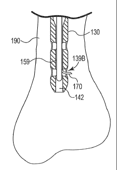
Referring now to FIGS. 15-22 an exemplary bone drilling operation using
intramedullary rod 130, drilling assembly 159, and step pin 147 in accordance
with the system of the invention will be explained. In order to prepare the
various
components described above for use in a drilling operation, a number of
exemplary steps can be perfolined. It should be understood that variations of
the
order of these steps are contemplated, along with the addition or deletion of
steps
or processes. Furthermore, the exemplary steps are described with reference to
the
components of the system previously described merely for purposes of example
and not limitation.
In this exemplary process, the drill motor assembly 171 may be connected
to the drilling assembly 159 by placing the motor housing 175 into the motor
guide tube 160. The motor guide cap 176 may then be connected to the motor
guide tube 160. The next step to prepare for the surgical drilling operation
is to
attach the femoral jig 186 to intramedullary rod 130, such as with a
carmulated
bolt. Intramedullary rod 130 is then inserted into the intramedullary cavity
of a
broken bone 190 as illustrated in FIG. 16A using any suitable insertion means.
Jig
interface 182 may be attached to the femoral jig 186, such as with the
cannulated
bolt used to attach the femoral jig 186 to intramedullary rod 130. A suction
rod or
a vacuum tube may then be inserted into the inner channel 142 of
intramedullary
rod 130 and attached to a vacuum source to extract extraneous fluids and
cancellous debris from the inner channel. Intramedullary rod 130 is now ready
for
insertion of the drilling assembly 159 so that the drilling operation may
begin.
The surgeon may slide the drilling assembly 159 into the channel 142 of
intramedullary rod 130 and use the internal structural features . of the rod
previously discussed to locate the desired one of the distal holes, such as
the
distal-distal hole 139B as illustrated in FIG. 16A. The hook 170 can then be
extended through the distal-distal hole 139B of intramedullary rod 130 as
illustrated in FIG. 17 by depressing the appropriate lever on the drilling
assembly
19
CA 02780985 2014-09-25
=
and sliding it distally. After the hook 170 has been fully deployed from the
guide
tube 168, the surgeon may begin the actual formation of the pilot hole by
drilling
through the distal-distal hole 139B.
As illustrated in FIGS. 16B-16D, the drilling assembly 159 may further
include a distal means to assist the surgeon with locating and/or securing the
desired
screw hole and maintaining the position of the drilling assembly 159 relative
to the
screw hole after it is located. Particularly, FIG. 16B is a diagram
illustrating one
exemplary alternative drilling assembly 159A having a protrusion 129 that is
sized
and structured to "snap" into the locking screw hole of the intramedullary rod
130.
As will be appreciated by those of ordinary skill in the art, the protrusion
129 may be
formed from any suitable material, and may be formed integral with or separate
from
the guide tube 168 of the drilling assembly. As further illustrated in FIG.
16B, the
protrusion 129 may include one or more ramped surfaces 131 to assist with the
insertion of the protrusion into the locking screw hole and removal of the
protrusion .
from the hole. FIG. 16F illustrates an alternative drilling assembly in which
protrusion 131 snaps into the locking screw hole of the intramedullary rod 130
located on the opposition side. As will be appreciate by those of ordinary
skill in the
art the protrusion 131 can be positioned at a variety of locations on the
drilling
assembly to snap into any screw hole or other receiving hole located on the
intramedullary rod.
FIG. 16C is a diagram illustrating another exemplary alternative drilling
assembly 159B having a protrusion 133 similar to the protrusion 129 of FIG.
16B
that is sized and structured to "snap" into the locking screw hole of the
intramedullary rod 130. However, the protrusion 133 is faulted on the distal
end of a
flexible member 135 extending from the drilling assembly 159B. The flexible
member 135 may be shaped generally like the hook 170 contained therein to
assist
with guiding the hook 170 into the locking screw hole. There may be chamfers
141
along the inside portion of the screw holes to facilitate insertion and
removal of the
drill assembly with such protrusions. Insertion and removal of the drill
assembly to
any hole within the nail may be performed either through translation and/or
rotation.
FIG. I 6D is a diagram illustrating yet another exemplary alternative drilling
assembly 159C having a ball detent 121 that is sized and structured to "pop"
into the
locking screw hole opposite the hole where the hook 170 will be
CA 02780985 2012-05-15
WO 2011/063184
PCT/US2010/057344
deployed. A coil spring 123 allows for radial movement of the ball detent 121
relative to the drilling assembly 159C and urges the ball detent into the
desired
locking screw hole when properly aligned. However, the ball detent 121 is also
easily removable from the locking screw hole by axial movement of the drilling
assembly 159C (either retraction or extension within the rod channel 142). As
will be appreciated by those of ordinary skill in the art, any type of surface
protrusion may be provided that engages the locking screw hole opposite the
hole
where the hook 170 will be deployed, such as a protrusion similar to that
illustrated in FIG. 16B. An advantage of incorporating a coil spring into the
design is the ease of engagement and disengagement with the locking screw
hole.
FIG. 16 E illustrates a drilling assembly in which the outer jacket is
flexible so that it may be easily positioned within the channel of the
intramedullary rod.
In order to commence formation of the pilot hole through the distal-distal
hole 139B, the surgeon may actuate the appropriate control button, such as a
start/stop button on a hand controller. The surgeon then monitors the progress
of
the operation while the rotating drilling wire 172 is advanced radially
outward
from the distal-distal hole 139B through the bone 190 and the tissue 192 as
illustrated in FIG. 18. The surgeon may then actuate the appropriate control
button, such as the start/stop button, to stop the drilling operation.
Optionally,
prior to advancing the drilling wire 172 through the distal-distal hole 139B,
the
surgeon may first compress the tissue 192 adjacent to where the pilot hole
will be
formed with a compression means 194 as illustrated in FIG 19A. As will be
appreciated by those of ordinary skill in the art, compressing the tissue 192
in this
region may minimize the risk that the elongate, drilling wire 172 will catch
the
tissue 192 as it is spinning and cause collateral damage to the tissue. One
exemplary compression means 194 is a block of semi-rigid foam. One of the
benefits of using a foam material is that after the drilling wire 172 reaches
the
surface of the skin 196, a tip 198 of the drilling wire 172 will puncture the
compression means 194 as illustrated in FIG. 19A, signifying to the surgeon
that
the pilot hole formation is complete. The compression means 194 may then be
removed from the surface of the skin 196.
A foam block is illustrated in FIG. 19A merely for purposes of example
and not limitation. As will be appreciated by those of ordinary skill in the
art, any
21
CA 02780985 2012-05-15
WO 2011/063184
PCT/US2010/057344
suitable compression means 194 may be used including, but not limited to, a
sterile wrap, a silicone based material, or the like. Additionally, the
devices may
contain a liquid internally, which when the drilling has penetrated through
the skin
and into the liquid region of these compression means, would provide the use
with
a visual indication to stop the drilling, as well as a tactile indication due
to the
pressure drop fat __ in the exiting liquid.
Alternatively, a more advanced
compression device such as the compression device 201 illustrated in FIG. 19B
may be used to provide a desired amount of compression on the tissue 192.
Particularly, the compression device 201 of FIG. 19B includes a generally disk-
shaped base 203 having an opening 205 therein, a tubular main body 207, and a
plurality of struts 209 extending between the base 203 and the main body 207.
As
will be appreciated by those of ordinary skill in the art, the surgeon may
manually
grasp the compression device 201, align the opening 205 in the base 203 with
the
expected exit location of the drilling wire 172, and apply pressure to the
base 203
to compress the tissue 192. Alternatively, as illustrated in FIG. 19C, the
compression device 201 may be structured for use with the guide arin 181
described above with reference to FIG. 11A. As illustrated in FIG. 19C, the
main
body 207 of the compression device 201 may be structured for insertion within
the
apertures 183 of the guide arm 181, and may be removably connected thereto
with
any suitable connection means as will be appreciated by those skilled in the
art.
Exemplary connection means may include, but are not limited to, a threaded
connection, a ball-and-socket connection, a set screw, clamps, or the like.
These
connections are not limited to a single dimension or direction, but may allow
adjustment and connections of the guide arm in multiple angles or positions.
When the compression device 201 is used in combination with the guide
arin 181, the amount of compression applied to the tissue 192 may be adjusted
with a compression adjustment means associated with the guide aim 181. In one
exemplary embodiment, a ratcheting mechanism may be incorporated into the
guide arm 181 for providing step-like increases in the amount of compression
applied to the tissue 192. In another exemplary embodiment, the tubular main
body 207 of the compression device 201 may be provided with external threads,
while the apertures 183 of the guide arin 181 may be provided with
corresponding
internal threads such that rotation of the main body 207 relative to the guide
arin
181 causes movement of the base 203 (and consequently, a controllable amount
of
22
CA 02780985 2012-05-15
WO 2011/063184
PCT/US2010/057344
compression). In yet another alternative embodiment, a pressure gauge may be
provided that is operable to apply a set compression force or a set
displacement
(which may be selected by the surgeon). Numerous other compression adjustment
means are contemplated and within the intended scope of the invention.
Optionally, the opening 205 in the base 203 of the compression device 201
may be covered with a suitable barrier material that provides for more unifoun
= compression of the tissue 192. The barrier material is preferably thin,
for example
a film, and may be solid or alternatively may include smaller openings, such
as a
webbing or mesh-like material.
As further illustrated in FIGS. 19B and 19C, the tubular main body 207 of
the compression device 201 may include an opening 211 that is sized and
structured for receiving various components including the drill sleeve, pin
sleeve,
drill bit, and/or step pin described below.
Next, as illustrated in the cross-sectional view of FIG. 20A, the surgeon
may create a small incision near the pilot hole in order to locate the
drilling wire
172. A series of cannulas with increasing diameters, ratcheting retractors, or
any
other suitable dilation means known to those of ordinary skill in the art may
be
used to dilate the incision to increase the surgeon's field of vision while
searching
for the exit point of the drilling wire 172. Once the drilling wire 172 is
located,
the surgeon may grasp the tip 198 of the drilling wire and adjust the drilling
wire
such that it is substantially perpendicular to the corresponding locking screw
hole.
The surgeon may then insert a drill sleeve 200 over the drilling wire 172.
Although not shown, the distal end of the drill sleeve 200, or retraction
means,
may include "teeth" or other suitable projections for gripping the surface of
the
bone. With the drill sleeve 200 or other retraction means, in place, the
surgeon
may adjust the position of the guide ann 181 of the rod interface assembly
180,
insert the proximal end of the drill sleeve 200 through one of the apertures
183,
and lock the guide arm 181 at the desired position. As will be appreciated by
those of ordinary skill in the art, the drill sleeve 200 or other retraction
means may
be structured to protect the tissue 192 surrounding the newly fonned pilot
hole to
prevent any unintended damage to the tissue during drilling and locking screw
placement.
As further illustrated in FIG. 20A, a pin sleeve 202 may also be inserted
into the tissue. A perspective view of the drill sleeve 200 and pin sleeve 202
23
CA 02780985 2012-05-15
WO 2011/063184
PCT/US2010/057344
positioned adjacent to the distal-distal hole 139B of intramedullary rod 130
is
illustrated in FIG. 20B. The drill and pin sleeves 200 and 202 may either be
inserted together (i.e., at the same time) or separately. As will be
appreciated by
those of ordinary skill in the art, the pin sleeve 202 may be structured to
receive
and guide the step pin 147. After inserting the drill sleeve 200 and pin
sleeve 202
into the tissue 192, the drilling wire 172 may be retracted into the guide
body 168,
at which time the step pin 147 can be inserted into the pin sleeve 202 and
used to
locate the pilot hole in the near cortex.
Aligning the step pin 147 with the pilot hole may occasionally prove
difficult, even with the assistance of the pin sleeve 202. Thus, in one
exemplary
alternative embodiment as illustrated in FIG. 20C, the pin sleeve 202 may
include
a window 213 in the side wall that allows for passage of the distal end of the
drilling wire 172. Particularly, the wire 172 may be pulled through the window
213 of the pin sleeve 202 to assist with alignment of the pin sleeve 202 with
the
location on the bone where the pilot hole was fonned. Once the pin sleeve 202
is
properly aligned, the step pin 147 may be inserted into the pin sleeve 202 and
the
drilling wire 172 retracted.
After the step pin 147 is inserted into the pilot hole, the hook 170 can be
retracted and the drilling assembly 159 can be pulled proximally by a small
distance to allow drilling through to the far cortex. With reference to the
exemplary drilling assembly 159, the hook 170 may be retracted by depressing
the
plunger on the deployment/retraction lever 162 and sliding the plunger
proximally
within the slot with a slight force until the hook is fully retracted. The pin
sleeve
202 may also be removed from the tissue 192 as illustrated in the cross-
sectional
view of FIG. 21A, leaving only the drill sleeve 200 and step pin 147 in the
tissue.
A perspective view of the step pin 147 extending through the drill sleeve 200
(with the pin sleeve 202 removed) and into the pilot hole is illustrated in
FIG.
21B.
As illustrated in the cross-sectional and perspective views of FIGS. 22A
and 22B, respectively, a cannulated drill bit 206 may then be slid over the
step
pin 147. A separate drill that is not associated with the drilling assembly
159 can
then be used to completely penetrate through the first cortical wall of the
bone
190. The drill can then be stopped and the cannulated drill bit 206 can be
advanced until the second cortical wall of the bone 190 is reached.
Optionally, in
24
CA 02780985 2012-05-15
WO 2011/063184
PCT/US2010/057344
order to confilin the proper placement of the cannulated drill bit 206, the
drilling
assembly 159 in intramedullary rod 130 may be moved distally within the
channel 142 until the surgeon can feel the distal end of the drilling assembly
touch the cannulated drill bit 206. The drilling assembly 159 may then be
retracted to its previous position, and the drill coupled to the cannulated
drill bit
206 may then be used to penetrate the second cortical wall. To reduce the
possibility of unintended tissue damage, it may be desirable to carefully
monitor
and limit the distance that the cannulated drill bit 206 extends beyond the
second
cortical wall.
After drilling through the second cortical wall of the bone 190, the
cannulated drill bit 206, step pin 147, and drill sleeve 200 may be removed to
expose the bi-cortical hole. A depth gauge may then be used to measure for the
appropriate length of locking screw, using conventional methods, and an
appropriately sized locking screw may then be inserted into the distal-distal
hole
139B in order to fasten intramedullary rod 130 in place.
A similar procedure to the one described with reference to the distal-distal
hole 139B may be used for drilling through the proximal-distal hole 139A.
It should be understood that variations of the order of the steps described
above with reference to FIGS. 15-22 are contemplated, along with the addition
or
deletion of steps or processes. Furthermore, the bone drilling process and
method
of using a step pin were described with reference to intramedullary rod 130,
the
drilling assembly 159, and the step pin 147 merely for purposes of example and
not limitation. Thus, alternative intramedullary rods, drilling assemblies,
and step
pins may also be used, such as the alternative step pins 161 and 191 described
above.
Additionally, as will be appreciated by those of ordinary skill in the art, it
may be possible to drill through the cortical walls of the bone 190 without
using a
step pin for guidance. For example, the cannulated drill bit 206 may include a
window 215 in the side wall that allows for passage of the distal end of the
drilling wire 172 in a manner similar to that previously described with
reference
to the window 213 in the pin sleeve 202. Particularly, after placement of the
drill
sleeve 200 in the incision, the cannulated drill bit 206 may be inserted into
the
drill sleeve 200 and the drilling wire 172 pulled through the window 215 to
align
the drill bit 206 with the pilot hole location. Once the cannulated drill bit
206 has
CA 02780985 2014-09-25
been properly aligned, the drilling wire 172 may be retracted and the holes in
the
cortical walls drilled as discussed above. Thus, as will be obvious to those
of
ordinary skill in the art, use of a drill bit with a window such as that
illustrated in
FIG. 23 may eliminate the need for a step pin altogether.
Although the present invention has been described with reference to preferred
embodiments, workers skilled in the art will recognize that changes may be
made in
form and detail without departing from the scope of the invention.
26