Note: Descriptions are shown in the official language in which they were submitted.
CA 02781025 2014-09-18
MAGNETIC ACTUATOR
BACKGROUND INFORMATION
[0001] Magnetic actuators typically include a relatively long spring that
is located
inside the center of the actuator mechanism. In many instances, the length of
the spring adds
to the overall length of the enclosure that houses the magnetic actuator. As a
result,
conventional magnetic actuators are too long to be used in many installations
due to the
overall length of the actuator and housing.
SUMMARY OF INVENTION
100021 In accordance with one aspect of the present invention, there is
provided a
magnetic actuator, comprising a coil bobbin including electrical wire wound
around a core, a
plunger located in a central portion of the magnetic actuator and configured
to move within a
bore located in the central portion, at least one spring located adjacent the
central portion,
wherein when electrical current is provided to the electrical wire, an
electromagnetic field
causes the plunger to move from a first position to a second position and
wherein stored
energy associated with the at least one spring aids in moving the plunger to
the second
position, a linking portion coupled to an upper portion of the plunger and
connected to a pull
rod assembly, wherein the linking portion is configured to initiate an action
via the pull rod
assembly based on movement of the plunger, and at least one booster magnet
located adjacent
the upper portion of the plunger, wherein the at least one booster magnet aids
in holding the
plunger in the first position when electrical current is not provided to the
coil bobbin.
1
CA 02781025 2014-09-18
[0002.1] In accordance with another aspect of the present invention, there
is provided a
system, comprising a circuit breaker, a moveable assembly coupled to the
circuit breaker and
configured to open or close the circuit breaker, and a magnetic actuator
comprising a coil
bobbin including electrical wire wound around a core, a plunger located in a
central portion of
the magnetic actuator and configured to move within an opening located in the
central
portion, at least one spring located adjacent the central portion, wherein
when electrical
current is provided to the electrical wire, an electromagnetic field causes
the plunger to move
from a first position to a second position, wherein stored energy associated
with the at least
one spring is used to aid in moving the plunger to the second position, a
linking portion
coupled to an upper portion of the plunger and connected to the moveable
assembly, wherein
the linking portion is configured to initiate the opening or closing of the
circuit breaker via the
moveable assembly, and at least one booster magnet located adjacent the upper
portion of the
plunger, wherein the at least one booster magnet operates to hold the plunger
in the first
position when electrical current is not provided to the electrical wire.
[0002.2] In accordance with a further aspect of the present invention,
there is provided a
magnetic actuator, comprising a coil bobbin including electrical wire wound
around a core, a
plunger located in a central portion of the magnetic actuator and configured
to move within a
bore located in the central portion, a booster magnet located adjacent an
upper portion of the
plunger, at least two springs located adjacent the central portion, wherein
when electrical
current is provided to the electrical wire, an electromagnetic field causes
the plunger to move
from a first position to a second position and wherein stored energy
associated with the at
least two springs aids in moving the plunger from the first position to the
second position, and
la
CA 02781025 2014-09-18
a linking portion coupled to the plunger and a moveable assembly, wherein the
linking portion
is configured to initiate an action via the moveable assembly based on
movement of the
plunger from the first position to the second position.
BRIEF DESCRIPTION OF THE DRAWINGS
[0003] Fig. 1 is a cross-sectional view of a magnetic actuator consistent
with an
exemplary embodiment;
[0004] Fig. 2 is a cross-sectional view of a magnetic actuator consistent
with another
exemplary embodiment; and
[0005] Fig. 3 is a block diagram illustrating use of the magnetic
actuator in a system
including a circuit breaker.
lb
CA 02781025 2012-06-22
DETAILED DESCRIPTION OF PREFERRED EMBODIMENTS
[0006] The following detailed description refers to the
accompanying drawings.
The same reference numbers in different drawings may identify the same or
similar elements.
Also, the following detailed description does not limit the invention.
[0007] Embodiments described herein provide a magnetic actuator
that has a low
profile and consumes less space than a conventional magnetic actuator. For
example, in one
embodiment, a magnetic actuator includes two springs located adjacent a
central portion of the
magnetic actuator. The two springs allow the magnetic actuator to be shorter
in length than
conventional actuators. In another embodiment, a single spring may be located
around the
circumference of the central portion of the magnetic actuator. In this
embodiment, the single
spring may also allow the magnetic actuator to be contained in an enclosure
that is shorter in
length than enclosures used to house conventional magnetic actuators. In each
case,
embodiments described herein allow a magnetic actuator to be used in scenarios
where space is
at a premium.
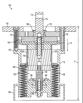
[0008] Fig. 1 is a cross-sectional view of a magnetic actuator 100
in accordance
with an exemplary embodiment. Referring to Fig. 1, magnetic actuator 100 may
include
mounting plate 110, housing 115, booster magnet 120, coil bobbin 130, plunger
140, springs 150,
back stop 160, pull rod linker 170, plunger connector 175, collar 180 and
spring disk 190. The
exemplary configuration illustrated in Fig. 1 is provided for simplicity. It
should be understood
that actuator 100 may include more or fewer devices than illustrated in Fig.
1. For example, the
coil windings associated with coil bobbin 130 are not shown for simplicity.
2
CA 02781025 2012-06-22
[0009] Mounting plate 110 may allow magnetic actuator 100 to be
mounted to
another structure. For example, mounting plate 110 may include openings for
screws 112 to
allow magnetic actuator 100 to be mounted within an enclosure or a cabinet, to
switchgear, etc.
As illustrated in Fig. 1, in one embodiment, mounting plate 110 may include
two screws 112 that
are used to secure mounting plate 110 to housing 115.
[0010] Housing 115 may be an enclosed structure that houses the
components
(e.g., booster magnet 120, coil bobbin 130, plunger 140, springs 150, back
stop 160, etc.) of
magnetic actuator 100. Housing 115 may be metal, plastic or a composite
material.
[0011] Booster magnet 120 may include a conventional magnet that is
used to
hold plunger 140 adjacent booster magnet 120 when coil bobbin 130 is not
energized, as shown
in Fig. 1. Booster magnet 120 may also aid in moving plunger 140 in a linear
direction when
electricity is applied to the coil/wire (not shown) wound on coil bobbin 130,
as described in more
detail below.
[0012] Coil bobbin 130 may include a bobbin used to hold a coil of
wire (not
shown in Fig. 1 for simplicity) wound around the core of coil bobbin 130. In
an exemplary
implementation, the core of coil bobbin may be made of a metallic material,
such as iron or steel.
An electrical power source (not shown in Fig. 1) may be coupled to the coil of
wire of coil
bobbin 130. When the windings of coil bobbin 130 become energized, coil bobbin
130 acts as
an electromagnet to move plunger 140 in the linear direction illustrated by
the arrow labeled A in
Fig. 1. That is, the electrical current provided to the coil bobbin 130 breaks
the magnetic field
holding plunger 140 to booster magnet 120 and acts to move plunger 140 in the
direction of
arrow A.
3
CA 02781025 2012-06-22
[0013] Plunger 140 may be made from a metallic material, such as
iron, steel or
some other metal that may be magnetic. Plunger 140 may be located in the
central portion of
magnetic actuator 100. For example, referring to Fig. 1, the upper portion of
plunger 140 may be
located adjacent booster magnet 120. Plunger 140 may move within opening/bore
145 when coil
bobbin 130 generates a magnetic field in response to current being applied to
coil bobbin 130.
This linear motion of plunger 140 may be used to perform an operation (e.g.,
open/close a circuit
breaker), as described in more detail below.
[0014] Booster magnet 120, as illustrated in Fig. 1, may be located
adjacent the
upper portion of plunger 140 and may be a permanent magnet. The magnetic field
of booster
magnet 120 may be oriented to hold plunger 140 adjacent booster magnet 120 in
the position
illustrated in Fig. 1. When coil bobbin 130 is energized, the electromagnetic
field created by coil
bobbin 130 breaks the magnetic field of booster magnet 120 holding plunger
140. As a result,
plunger 140 moves in the direction illustrated by arrow A.
[0015] As described above, magnetic actuator 100 may include two
inner springs
150 located within housing 115. Springs 150 may include coil springs or other
types of springs.
Spring disk 190 may include a housing that is coupled to the lower portion of
plunger 140. For
example, referring to Fig. 1, spring disk 190 may include a spring disk
coupler 192 that connects
spring disk 190 to plunger 140 via plunger coupler 194. Spring disk 190 may
provide a tension
or compressive force on springs 150 to create a stored energy in springs 150
when plunger 140 is
located in the position illustrated in Fig. 1. This stored energy may be used
to aid in movement
of plunger 140 when coil bobbin 130 is energized.
4
CA 02781025 2012-06-22
[0016] For example, referring to Fig. 1, when plunger 140 moves in
the direction
of arrow A, the downward force on plunger 140 moves spring disk 190 and allows
springs 150 to
use the stored energy and assist in movement of plunger 140. That is, the
stored energy may be
released to allow springs 150 to aid in moving plunger 140. Spring disk 190
may also include a
label that will indicate to a user whether a circuit breaker coupled to
magnetic actuator 100 is in
the open or closed position.
[0017] Back stop 160 may act as a restraining point to stop plunger
140 from
moving past back stop 160. That is, back stop 160 may act to control the
distance of travel of
plunger 140. The distance of travel, also referred to as the stroke distance,
may be used to
operate or effect actuation of another device, such as open/close a circuit
breaker.
[0018] Pull rod linker 170 may be part of a pull rod assembly (not
shown) that
uses the linear motion of plunger 140 to effect a desired operation. For
example, in one
implementation, pull rod linker 170 may connect to a pull rod that is used to
open/close a
vacuum circuit breaker based on the linear motion of the pull rod, as
described in more detail
below. Pull rod linker 170 may include a portion, labeled 172 in Fig. 1, to
which a pull rod may
be attached. In alternative implementations, the upper portion of pull rod
linker 170 may be
threaded to receive a pull rod.
[0019] Plunger connector 175 may couple pull rod linker 170 to
plunger 140 so
that movement of plunger 140 is translated to movement of pull rod linker 170.
In other words,
pull rod linker 170 acts to provide a pulling force on a pull rod assembly to
actuate an operation,
such as open/close a circuit breaker. A collar 180 or other mechanical
coupling mechanism
CA 02781025 2012-06-22
. ..
located adjacent booster magnet 120 may secure pull rod linker 170 within
magnetic actuator 100
and allow pull rod linker 170 to move up/down as plunger 140 moves.
[0020] As described above, in conventional magnetic
actuators, a single central
spring may compress when the magnetic actuator is energized. Typically, the
spring is relatively
long and significantly adds a to the overall length of the magnetic actuator.
In accordance with
the implementation described above with respect to Fig. 1, two springs 150
located within the
magnetic actuator 100 housing 115 enable magnetic actuator 100 to be much
smaller (e.g., have a
shorter profile) than conventional magnetic actuators. For example, in
accordance with one
implementation, magnetic actuator 100 may have an overall length (labeled L in
Fig. 1) ranging
from approximately 4.0 inches to approximately 6.0 inches. In one particular
implementation in
which magnetic actuator 100 is used to open/close a vacuum circuit breaker, L
may be
approximately 5.66 inches in length. In other implementations, L may be less
than four inches in
length or greater than six inches in length. In each case, using two inner
springs 150, as opposed
to a single central spring allows magnetic actuator 100 to have a
shorter/lower profile such that
magnetic actuator can be used in a number of scenarios in which space is at a
premium.
[0021] Fig. 2 is a cross-sectional view of a magnetic
actuator 200 in accordance
with another exemplary embodiment. Referring to Fig. 2, magnetic actuator 200
may include
mounting plate 210, mounting screws 212, housing 215, booster magnet 220, coil
bobbin 230,
plunger 240, spring 250, back stop 260, pull rod linker 270, plunger connector
275, collar 280
and spring disk 290. The exemplary configuration illustrated in Fig. 2 is
provided for simplicity.
It should be understood that actuator 200 may include more or fewer devices
than illustrated in
6
CA 02781025 2012-06-22
.=
Fig. 2. For example, the coil windings associated with coil bobbin 230 are not
shown for
simplicity.
[0022] Mounting plate 210, similar to mounting plate 110 described
above with
respect to Fig. 1, may allow magnetic actuator 200 to be mounted to another
structure. For
example, mounting plate 210 may include openings for screws 212 to allow
magnetic actuator
200 to be mounted within an enclosure or a cabinet, to switchgear, etc. As
illustrated in Fig. 2, in
one embodiment, mounting plate 210 may include two screws 212 that are used to
secure
mounting plate 210 to housing 215.
[0023] Booster magnet 220 may include a conventional (e.g.,
permanent) magnet
that is used to hold plunger 240 adjacent booster magnet 220 when coil bobbin
230 is not
energized, as shown in Fig. 2. Booster magnet 220 may also aid in moving
plunger 240 in a
linear direction when electricity is applied to the coil/wire (not shown)
wound on coil bobbin
230, as described in more detail below.
[0024] Coil bobbin 230 may include a bobbin used to hold a coil of
wire (not
shown in Fig. 2 for simplicity) wound around the core of coil bobbin 230. In
an exemplary
implementation, the core of coil bobbin may be made of a metallic material,
such as iron or steel.
An electrical power source (not shown in Fig. 2) may be coupled to the coil of
wire of coil
bobbin 230 to provide current to the wire/windings. When the windings of coil
bobbin 230
become energized, coil bobbin 230 acts as an electromagnet to move plunger 240
in the linear
direction illustrated by the arrow labeled A in Fig. 2. That is, the
electrical current provided to
coil bobbin 230 generates a magnetic field that breaks the magnetic field of
booster magnet 220
holding plunger 240. As a result, plunger 240 moves in the direction
illustrated by arrow A.
7
CA 02781025 2012-06-22
[0025] Plunger 240 may be made from a metallic material, such as
iron, steel or
some other metal that may be magnetic. Plunger 240 may be located in the
central portion of
magnetic actuator 200. For example, referring to Fig. 2, the upper portion of
plunger 240 may be
located adjacent booster magnet 220. Plunger 240 may move within opening/bore
245 when coil
bobbin 230 generates a magnetic field in response to current being applied to
coil bobbin 230.
This linear motion of plunger 240 may be used to perform an operation (e.g.,
open/close a circuit
breaker), as described in more detail below.
[0026] Booster magnet 220, as illustrated in Fig. 2, may be located
adjacent the
upper portion of plunger 240 and may be a permanent magnet. The magnetic field
of booster
magnet 220 may be oriented to hold plunger 240 adjacent booster magnet 220 in
the position
illustrated in Fig. 2. When coil bobbin 230 is energized, the electromagnetic
field created by coil
bobbin 230 breaks the magnetic field of booster magnet 220 holding plunger 240
and plunger
240 moves in the direction illustrated by arrow A.
[00271 As described above, magnetic actuator 200 may include a
spring 250
located externally with respect to housing 215. Spring 250 may be a helically
wound spring or
another type of spring that surrounds the circumference of the center portion
of magnetic actuator
200. Spring disk 290 may include a housing that is coupled to the lower
portion of plunger 240.
For example, referring to Fig. 2, spring disk 290 may include a spring disk
coupler 292 that
connects spring disk 290 to plunger 240 via plunger coupler 294. Spring disk
290 may provide a
tension or compressive force on spring 250 to create a stored energy in spring
250 when plunger
240 is located in the position illustrated in Fig. 2. This stored energy may
be used to aid in
movement of plunger 240 when coil bobbin 230 is energized.
8
CA 02781025 2012-06-22
. .
[00281 For example, referring to Fig. 2, when plunger 240
moves in the direction
of arrow A, the downward force on plunger 240 moves spring disk 290 and allows
spring 250 to
use the stored energy and assist in movement of plunger 240. That is, the
stored energy may be
released to allow spring 250 to aid in moving plunger 240. Spring disk 290 may
also include a
label that will indicate to a user whether a circuit breaker coupled to
magnetic actuator 200 is in
the open or closed position.
[0029] Back stop 260 may act as a restraining point to stop
plunger 240 from
moving past back stop 260. That is, back stop 260 may act to control the
distance of travel of
plunger 240. The distance of travel, also referred to as the stroke distance,
may be used to
operate or effect actuation of another device, such as open/close a circuit
breaker.
[0030] Pull rod linker 270 may be part of a pull rod assembly
(not shown) that
uses the linear motion of plunger 240 to effect a desired operation. For
example, in one
implementation, pull rod linker 270 may connect to a pull rod that is used to
open/close a
vacuum circuit breaker based on the linear motion of the pull rod, as
described in more detail
below. Pull rod linker 270 may include an opening 272 to which a pull rod may
be inserted or
attached. In alternative implementations, the upper portion of pull rod linker
270 may be
threaded to receive a pull rod.
[0031] Plunger connector 275 may couple pull rod linker 270
to plunger 240 so
that movement of plunger 240 is translated to movement of pull rod linker 270.
In other words,
pull rod linker 270 acts to provide a pulling force on a pull rod assembly to
open/close a breaker
or actuate another operation. A collar 280 or other mechanical coupling
mechanism located
9
CA 02781025 2012-06-22
adjacent booster magnet 220 may secure pull rod linker 270 within magnetic
actuator 200 and
allow pull rod linker 270 to move up/down as plunger 240 moves.
[0032] As
described above, in conventional magnetic actuators, a single spring
located in the center of the magnetic actuator may compress when the magnetic
actuator is
energized. In accordance with the implementation described above with respect
to Fig. 2, spring
250 located externally with respect to housing 215 and around the
circumference of the central
portion of magnetic actuator 200 enables magnetic actuator 200 to be much
smaller (e.g., have a
shorter profile) than conventional magnetic actuators. For example, in
accordance with one
implementation, magnetic actuator 200 may have an overall length (labeled L in
Fig. 2) ranging
from approximately 4.0 inches to approximately 6.0 inches. In one particular
implementation in
which magnetic actuator 200 is used to open/close a vacuum circuit breaker, L
may be
approximately 5.66 inches in length. In other implementations, L may be less
than four inches in
length or greater than six inches in length. In each case, using a single
spring located around the
circumference of housing 215, as opposed to a single central spring located in
the central portion
of a magnetic actuator, allows magnetic actuator 200 to have a shorter/lower
profile such that
magnetic actuator 200 can be used in a number of scenarios in which space is
at a premium.
[0033] As
described above, magnetic actuator 100 or 200 may be used in a number of
implementations in which conventional magnetic actuators may not be used due
to, for example,
space considerations. Fig. 3 is a simplified block diagram of an exemplary
environment 300 in
which magnetic actuator 100 or 200 may be used. Referring to Fig. 3,
environment 300 includes
magnetic actuator 100 or 200, vacuum circuit breaker 310 and pull rod assembly
320. Pull rod
assembly 320 may include a cable or some other structure that couples pull rod
linker 170/270 of
CA 02781025 2012-06-22
magnetic actuator 100/200 to vacuum circuit breaker 310. As described above
with respect to
Figs. 1 and 2, pull rod assembly 170/270 may be coupled to magnetic actuator
100/200 via a
clamping mechanism, a threaded connection, a bolt-on connection or via some
other mechanism.
Pull rod assembly 320 may move in direction A illustrated in Fig. 3 in
response to movement of
plunger 140 or 240. The linear movement of pull rod assembly 320 may be used
to open or close
vacuum circuit breaker 310. For example, in one embodiment, the movement of
pull rod
assembly 170/270 may move pull rod assembly 320 to open the contacts of vacuum
circuit
breaker 310. Alternatively, movement of pull rod assembly 320 may actuate a
trip mechanism to
open or close vacuum circuit breaker 310. In each case, magnetic actuator 100
or 200 may be
used to trip vacuum circuit breaker 310 at the appropriate time based on the
particular
conditions/requirements associated with operating conditions in environment
300.
[0034] Once magnetic actuator 100 or 200 is activated, the contacts
in vacuum
circuit breaker 310 are opened/closed, based on the particular implementation.
After actuation,
the electrical current applied to coil bobbin 130 or 230 may be removed and
the contacts in
vacuum circuit breaker 310 remain in the desired position.
[0035] In the embodiments described above, two springs 150 or a single
spring 250 may
be used in connection with magnetic actuator 100/200. In some implementations,
springs 150
and 250 may be coil springs/helically wound springs. In other implementations,
other types of
springs may be used. For example, in another implementation, a Belleville type
washer may be
used in place of springs 150 and/or spring 250. In still other
implementations, a spring made in a
tube-like structure may be used in place of springs 150 and/or spring 250.
11
CA 02781025 2012-06-22
[0036] In addition, two springs 150 were described above with respect to
magnetic
actuator 100. In other implementations, three or more springs may be used in
magnetic actuator
100. For example, four springs located around the circumference of coil bobbin
130 may be
used. In such an implementation, the four springs may be offset 90 degrees
from each other. In
still other implementations, other numbers of springs (e.g., three or five or
more) may be used in
magnetic actuator 100.
[0037] In addition, in the embodiments described above refer to effecting
an operation,
such as opening or closing a circuit breaker. In other embodiments, magnetic
actuator 100/200
may be used to effect other operations, such as opening/closing a valve,
turning on/off a switch,
etc. In addition, embodiments have been described above with respect to
magnetic actuators
100/200 coupled to a pull rod assembly that actuates an operation. In other
embodiments,
magnetic actuator 100/200 may be used in connection with a push rod assembly
that is pushed in
a direction away from the magnetic actuator 100/200 to actuate an operation.
[0038] The foregoing description of exemplary implementations provides
illustration and
description, but is not intended to be exhaustive or to limit the embodiments
described herein to
the precise form disclosed. Modifications and variations are possible in light
of the above
teachings or may be acquired from practice of the embodiments.
[0039] For example, in some implementations, magnetic actuators 100/200
may not
include booster magnets 120/220. Further, other types of connection mechanisms
may be used to
couple magnetic actuators 100/200 to various systems/devices to actuate an
operation.
[0040] Although the invention has been described in detail above, it is
expressly
understood that it will be apparent to persons skilled in the relevant art
that the invention may be
12
CA 02781025 2014-09-18
modified. Various changes of form, design, or arrangement may be made to the
invention.
The scope of the claims should not be limited by the preferred embodiments set
forth in the
examples, but should be given the broadest interpretation consistent with the
description as a
whole.
[0041] No element, act, or instruction used in the description of the
present
application should be construed as critical or essential to the invention
unless explicitly
described as such. Also, as used herein, the article "a" is intended to
include one or more
items. Further, the phrase "based on" is intended to mean "based, at least in
part, on unless
explicitly stated otherwise.
13