Note: Descriptions are shown in the official language in which they were submitted.
CA 02781419 2012-05-18
WO 2011/066193 PCT/US2010/057448
WATER DESALINATION USING DIRECTIONAL SOLVENT EXTRACTION
BACKGROUND
In this century, the shortage of fresh water is expected to surpass the
shortage of
energy as a global concern for humanity, and these two challenges are
inexorably linked. Fresh
water is one of the most fundamental needs of humans and other organisms. Each
human
needs to consume a minimum of about two liters per day in addition to greater
fresh-water
demands from farming as well as from industrial processes. Meanwhile,
techniques for
transporting fresh water or for producing fresh water via desalination tend to
be highly
demanding of increasingly scarce supplies of affordable energy.
The hazards posed by insufficient water supplies are particularly acute. A
shortage of
fresh water may lead to famine, disease, death, forced mass migration, cross-
region
conflict/war (from Darfur to the American southwest), and collapsed
ecosystems. In spite of
the criticality of the need for fresh water and the profound consequences of
shortages,
supplies of fresh water are particularly constrained. 97.5% of the water on
Earth is salty, and
about 70% of the remainder is locked up as ice (mostly in ice caps and
glaciers), leaving only
0.75% of all water on Earth as available fresh water.
Moreover, that 0.75% of available fresh water is not evenly distributed. For
example,
heavily populated developing countries, such as India and China, have many
regions that are
subject to scarce supplies. Further still, the supply of fresh water is often
seasonally
inconsistent. Typically confined to regional drainage basins, water is heavy
and its transport is
expensive and energy-intensive.
Meanwhile, demands for fresh water are tightening across the globe. Reservoirs
are
drying up; aquifers are falling; rivers are dying; and glaciers and ice caps
are retracting. Rising
populations increase demand, as do shifts in farming and increased
industrialization. Climate
change poses even more threats in many regions. Consequently, the number of
people facing
water shortages is increasing.
Massive amounts of energy are typically needed to produce fresh water from
seawater
(or to a lesser degree, from brackish water), especially for remote locations.
Reverse osmosis
(RO) is currently the leading desalination technology, but it is energy
intensive and still
relatively inefficient due to the large pressures required to drive water
through semi-
permeable membranes and their tendency for fouling. In large-scale plants, the
energy/volume
1
CA 02781419 2012-05-18
WO 2011/066193 PCT/US2010/057448
required can be as low as 4 kWh/m3 at 30% recovery, compared to the
theoretical minimum
around 1 kWh/m3, although smaller-scale RO systems (e.g., aboard ships) have
much worse
efficiency, by an order of magnitude. Another popular method is the multi-
stage flash (MSF)
distillation, also an energy and capital intensive process.
Rather than extracting pure water, electrochemical methods, such as
electrodialysis
(ED) and capacitive desalination (CD), extract just enough salt to achieve
potable water (< 10
mM). Current large-scale electrochemical desalination systems are less
efficient than RO plants
at desalinating seawater (e.g., 7 kWh/m3 is the state of the art in ED), but
become more
efficient for brackish water (e.g., CD can achieve 0.6 kWh/m3). In general,
existing techniques
for removing salt from water, some of which have existed for centuries, tend
to be expensive
or complicated or both.
SUMMARY
Methods and apparatus for water desalination using directional solvent
extraction are
described herein. Various embodiments of the apparatus and method may include
some or all
of the elements, features and steps described below.
Certain solvents, such as edible oils (e.g., soybean oil) and some fatty
acids, possess an
unusual characteristic of being able to directionally dissolve water while not
dissolving other
water-soluble salts, such as sodium chloride, or impurities and while being
insoluble or almost
insoluble in water (i.e., water dissolves into the majority directional
solvent phase, but the
directional solvent does not dissolve into the majority water phase by more
than trace
amounts). This directional-solubility phenomenon is exploited, herein, in a
new method of
temperature-controlled desalination of a saline solution.
In an example of the method, a saline solution (e.g., sea water) is brought
into contact
with a directional solvent. The directional solvent can include a carboxylic
acid (i.e., a
compound that includes a carboxyl group, R-COOH), such as decanoic acid,
CH3(CH2)8COOH.
The saline solution and solvent are heated before or after contact to enhance
the directional
dissolution of water into the solvent and to thereby produce distinct phases,
a first phase that
includes the solvent and water from the saline solution and a second phase
that includes a
highly concentrated remainder of the saline solution. The first phase
separates from the
second phase and is extracted. Alternatively, the second phase can be
extracted from the first
phase. After extraction, the first phase is cooled to precipitate the water
from the solvent; and
2
CA 02781419 2012-05-18
WO 2011/066193 PCT/US2010/057448
the precipitated water is then removed from the solvent. The extracted water
can be in the
form of substantially pure water (e.g., suitable for industrial or
agricultural use or even meeting
drinking-water standards of purity, such as 99.95% purity).
The methods of this disclosure can use low-quality heat, which can come from
terrestrial heat sources, from the ocean, from the sun, or as waste heat from
other processes.
These desalination methods can also be easy to use and can offer significant
energy and
economic savings over present desalination methods.
BRIEF DESCRIPTION OF THE DRAWINGS
FIG. 1 is a schematic illustration of a directional solvent extraction
desalination process,
at lab scale.
FIG. 2 is an illustration of an initial stage in the process, wherein saline
water is mixed
with a directional solvent.
FIG. 3 is an illustration showing the use of a stirring plate to stir the
mixture of the
saline water and solvent to create an emulsion.
FIG. 4 is an illustration showing immersion of the emulsion in a hot-water
bath to raise
the temperature of the emulsion.
FIG. 5 is an illustration showing separation of the heated emulsion into a top
layer of
solvent with dissolved water and a bottom layer of highly concentrated saline
water.
FIG. 6 is an illustration showing decantation of the top layer of solvent and
dissolved
water into a tube.
FIG. 7 is an illustration showing the cooling of the decanted solvent and
dissolved water
to precipitate small droplets of water from the solvent.
FIG. 8 is an illustration showing the use of dielectrophoresis to separate the
droplets of
water from the solvent, with the separated water collecting at the bottom of
the tube.
FIG. 9 is an illustration showing the recovery of substantially pure water
from the
bottom of the tube.
FIG. 10 is an illustration showing the use of a stirring plate to stir a
mixture of saline
water and decanoic acid solvent to create a heated emulsion.
FIG. 11 is an illustration showing the separation of the heated emulsion into
a top layer
of decanoic acid with dissolved water and a bottom layer of highly
concentrated saline water.
3
CA 02781419 2012-05-18
WO 2011/066193 PCT/US2010/057448
FIG. 12 is an illustration showing decantation of the top layer of solvent and
dissolved
water into a tube heated in a bath of hot water.
FIG. 13 is an illustration showing the use of dielectrophoresis in a heated
tube to
separate the droplets of water from the solvent, with the separated water
collecting at the
bottom of the tube.
FIG. 14 is a chart plotting fresh water yield from decanoic acid solvent as a
function of
temperature.
FIG. 15 is a chart plotting exergy consumption for a desalination process
using decanoic
acid as a solvent as a function of temperature.
In the accompanying drawings, like reference characters refer to the same or
similar
parts throughout the different views. The drawings are not necessarily to
scale, emphasis
instead being placed upon illustrating particular principles, discussed below.
DETAILED DESCRIPTION
The foregoing and other features and advantages of various aspects of the
invention(s)
will be apparent from the following, more-particular description of various
concepts and
specific embodiments within the broader bounds of the invention(s). Various
aspects of the
subject matter introduced above and discussed in greater detail below may be
implemented in
any of numerous ways, as the subject matter is not limited to any particular
manner of
implementation. Examples of specific implementations and applications are
provided primarily
for illustrative purposes.
Unless otherwise defined, terms (including technical and scientific terms)
used herein
have the same meaning as commonly understood by one of ordinary skill in the
art to which
this invention belongs. It will be further understood that terms, such as
those defined in
commonly used dictionaries, are to be interpreted as having a meaning that is
consistent with
their meaning in the context of the relevant art and are not to be interpreted
in an idealized or
overly formal sense unless expressly so defined herein. For example, if a
particular composition
is referenced, practical, imperfect realities may apply; e.g., the potential
presence of at least
trace impurities (e.g., at less than 0.1% by weight or volume) can be
understood as being
within the scope of the description.
Although the terms, first, second, third, etc., may be used herein to describe
various
elements, these elements are not to be limited by these terms. These terms are
simply used to
4
CA 02781419 2012-05-18
WO 2011/066193 PCT/US2010/057448
distinguish one element from another. Thus, a first element, discussed below,
could be termed
a second element without departing from the teachings of the exemplary
embodiments.
Spatially relative terms, such as "above," "upper," "beneath," "below,"
"lower," and the
like, may be used herein for ease of description to describe the relationship
of one element to
another element, as illustrated in the figures. It will be understood that the
spatially relative
terms are intended to encompass different orientations of the apparatus in use
or operation in
addition to the orientation depicted in the figures. For example, if the
apparatus in the figures
is turned over, elements described as "below" or "beneath" other elements or
features would
then be oriented "above" the other elements or features. Thus, the exemplary
term, "above,"
may encompass both an orientation of above and below. The apparatus may be
otherwise
oriented (e.g., rotated 90 degrees or at other orientations) and the spatially
relative descriptors
used herein interpreted accordingly.
Further still, in this disclosure, when an element is referred to as being on,
"connected to" or "coupled to" another element, it may be directly on,
connected or coupled
to the other element or intervening elements may be present unless otherwise
specified.
The terminology used herein is for the purpose of describing particular
embodiments
and is not intended to be limiting of exemplary embodiments. As used herein,
the singular
forms "a," "an" and "the" are intended to include the plural forms as well,
unless the context
clearly indicates otherwise. Additionally, the terms, "includes," "including,"
"comprises" and
"comprising," specify the presence of the stated elements or steps but do not
preclude the
presence or addition of one or more other elements or steps.
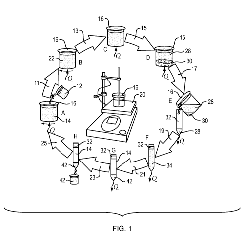
A batch, lab-scale exemplification of a desalination process is broadly and
schematically
illustrated in FIG. 1 with various stages shown in greater detail in FIGS. 2-
9. The process can
also be carried out on a larger, industrial scale using larger, automated
apparatus. Moreover,
the process can also be conducted in a continuous, staged process, where the
saline solution is
continuously input and substantially pure water is continuously output.
The process of FIG. 1 commences at stage A with the addition of a saline
solution 12
and heat, Q, to a directional solvent 14 in a container 16. The directional
solvent 14 and saline
solution 12 are mixed 11 to produce an emulsion 22, as shown in stage B. With
the addition of
more heat, Q, water from the saline solution then dissolves 13 into the
directional solvent
5
CA 02781419 2012-05-18
WO 2011/066193 PCT/US2010/057448
through stage C; and the concentrated remainder 30 of the saline solution
settles 15 to the
bottom of the container 16 into stage D.
The container 16 is then removed from the heat source and the solution of
water in the
directional solvent is decanted 17 from the container into a secondary vessel
in stage E and left
to cool to precipitate 19 water from the solution, as shown in stage F. The
precipitated water
settles 21 to the bottom of the vessel in stage G and is then recovered 23 as
substantially pure
water from the bottom of the vessel in stage H. As shown, the directional
solvent can then be
reused 25 as the process is repeated with additional saline solution.
Revisiting the steps of this process from the beginning in a more-specific
example,
starting with FIG. 2 (stage A in FIG. 1), a saline solution 12 is added to a
container (e.g., a
beaker) 16 filled with a directional solvent 14 at or near room temperature
(e.g., 25-35 C). The
saline solution 12 can be naturally occurring-for example, in the form of
saline water
extracted from the sea. The directional solvent 14 can be, for example, an
edible oil, such as
soybean oil, palm oil, rapeseed oil, coconut oil or linseed soil, that
includes fatty acids.
Alternatively, the directional solvent can consist essentially of one or more
select fatty acids.
Suitable fatty acids can include carbon chains of, for example, 6 to 13 carbon
atoms, such as
decanoic acid, which has a carbon chain length of 10 carbon atoms. The fatty
acid can also be a
solid at room temperature (e.g., at about 30 C and/or below). Decanoic acid is
considered
substantially insoluble in water (e.g., dissolving in water up to only about
40-50 parts per
million); and decanoic acid is relatively harmless to humans, as it is
naturally found in milk. In
the methods for separating water from a saline solution, a hydrophilic
hydroxide group from
the fatty acid may bind to water from the saline solution.
The container 16 with the combined saline solution 12 and the directional
solvent 14
are then mixed to form an emulsion. As shown in FIG. 3 (stage B in FIG. 1), in
a lab-scale setting,
mixing can be carried out on a magnetic stirring plate 20 with a magnetic
stirrer 18 dropped
into the container 16. The stirring plate 20 magnetically displaces the
magnetic stirrer 18 in the
container 16 to vigorously mix the solvent 14 and saline solution 12 to
produce an emulsion 22
of the two liquids. Mixing is conducted until the emulsion 22 appears cloudy
to the eye (e.g., in
this embodiment, for about 30 seconds).
The emulsion 22 in the container 16 is exposed a heat source 24 (e.g., in the
form of a
hot water bath), as shown in FIG. 4 (stage C in FIG. 1), and preheated up to a
preheat
6
CA 02781419 2012-05-18
WO 2011/066193 PCT/US2010/057448
temperature of, for example, about 75 C or, in other embodiments, only to a
temperature as
low as about 40 C, with the elevated temperature reflected by the elevated
mercury in the
illustrated thermometer 26. Alternatively, the solvent 14 and/or saline
solution 12 be heated
before contact or mixing. The heat can be provided, e.g., by waste heat from
another process
or from terrestrial heat sources, from the ocean, or from simple solar heating
from the sun.
The emulsion 22 remains subjected to the heat source to maintain the preheat
temperature
(e.g., for a day) to allow water from the saline solution droplets in the
emulsion 22 to dissolve
into the directional solvent.
The solution 28 of the solvent with the dissolved water rises to the top of
the container
16 and appears clear to the eye, while the concentrated remainder 30 of the
saline solution
separates to the bottom of the container 16, as shown in FIG. 5 (stage D in
FIG. 1).
The container 16 is then removed from the heat source 24 and the solution 28
including
the solvent and the dissolved water is decanted from the container 16 into
secondary vessels
32 (e.g., in the form of conical tubes), as shown in FIG. 6 (stage E in FIG.
1), and left to cool
(e.g., in ambient air) back to room temperature, as shown in FIG. 7 (stage F
in FIG. 1). As the
solution 28 cools, the solution 28 turns cloudy, indicating the precipitation
of small droplets of
water to form an emulsion 34.
Optionally, to expedite separation of the precipitated water and separation of
the
water from the solvent, the emulsion 34 of the precipitated water and solvent,
while held in
the tube 32 in a stand 33, can be subject to dielectrophoresis, as shown in
FIG. 8 (stage G in
FIG. 1). As shown, a power supply 40 is coupled via conductive wires 38 to a
pair of electrodes
35 and 36 positioned at the bottom and top of the vessel 32. The power supply
40 produces a
potential difference across the electrodes 35 and 36, wherein the non-
uniformity of the
electrode shape (e.g., a flat plate at one end and a needle at the other end)
produces a non-
uniform electric field that acts on the water droplets to separate them from
the solvent.
Consequently, substantially pure water 42, which has a greater density than
the solvent, is
collected at the bottom of the vessel 32 and removed via a hole in the bottom
of the vessel and
collected in a water reservoir 44 (in this embodiment, in the form of a
beaker), as shown in FIG.
9 (stage H in FIG. 1).
The substantially pure water 42 can have a weight-to-weight salt content of,
e.g., less
than 1.5%, less than 0.14%, or less than 0.05%. Optionally, an additional
desalination can be
7
CA 02781419 2012-05-18
WO 2011/066193 PCT/US2010/057448
employed after the above-described water-separation methods to reach a higher
level of water
purity. For example, a second stage of desalination can be in the form of
reverse osmosis or
flash distillation.
In large systems, heat recuperation may be used to improve the system
efficiency. For
example, heat released in cooling to precipitate out pure water can be used
for heating up the
salt-water-in-oil emulsion.
One application for these apparatus and methods is in petroleum oil or natural
gas
production, wherein the directional solvent can be used to separate salts and
other
components that are insoluble in the directional solvent from, for example,
"produced water"
(i.e., water that is produced along with the oil and gas) or "fracking water"
(i.e., water from
hydraulic fracturing) that is generated, in particular, when extracting oil
from tar sands or when
extracting natural gas from shale. The fracking water can have a salt
concentration three times
as great as that of typical sea water and can include, for example, benzene
and heavy metals.
And typically, the produced water or fracking water is transported offsite for
treatment and/or
containment in above-ground pools
Both reverse osmosis and multi-stage flash exhibit lower performance in
produced or
fracking water treatment, where a much higher salinity in the produced or
fracking water
increases energy consumption and causes increased membrane fouling. By instead
mixing the
produced water with the directional solvent, most of the water can be
extracted in
substantially pure form using relatively low energy and heat inputs and at a
reasonable cost,
leaving a much more concentrated and lower volume waste product and allowing
the
extracted water to be reused in the oil extraction process, thereby offering
substantial
environmental benefits in terms of waste containment, lower water demands,
less
environmental pollution and greater efficiency.
Exemplification 1:
Materials, Methods, and Observations:
In a first experiment, soybean oil was used as the directional solvent.
Soybean oil has a
water saturation limit of 0.3% by volume at 25 C, and this saturation limit is
expected to nearly
double at 60 C. Soybean oil is inexpensive and readily available.
8
CA 02781419 2012-05-18
WO 2011/066193 PCT/US2010/057448
An aqueous solution of sodium chloride was prepared to simulate sea water. The
salt
content of this solution was measured using a Horiba Salt Meter and was found
to be 3.367%
0.115%.
About 6 ml of this salt solution were added to about 300 ml of soybean oil and
mixed
vigorously in a container on a stirring plate to produce an emulsion of salt
solution in oil. The
mixture was stirred for about 30 seconds until the contents of the container
appeared cloudy
to the eye.
This emulsion container was then placed in a hot water bath preheated to 75 C.
The
emulsion was left in the hot water bath for 24 hours (this incubation period
may readily be
decreased or increased to optimize processing speed or output) to allow some
water from the
emulsion droplets to dissolve into the oil. This directional dissolution of
water into the oil is
expected to render the remaining droplets highly concentrated with salt, and
these droplets
are expected to separate under gravity to the bottom of a container.
After 24 hours of incubation, the emulsion container was taken out of the hot
water
bath. As expected, a significant amount of the salt solution had separated to
the bottom of the
container, and the oil above appeared clear to the eye. This change from
cloudy to clear
indicates that the emulsion droplets either dissolved, or separated to the
bottom of the
container.
The oil above the separated salt solution was decanted into six different 50
ml conical
tubes and left to cool in air at room temperature. As expected, after several
hours of cooling
down, the oil appeared to turn cloudy again, indicating the precipitation of
small droplets of
water.
To expedite the process of separation of this precipitated water and its
separation from
oil, the emulsions were subjected to dielectrophoresis. In the
dielectrophoresis process, a non-
uniform electric field was used to separate particulates (here, water
droplets) from a host fluid
(here, oil). Specifically, the mixture was subjected to an electric field of
about 2 kV/ cm for
about 5 minutes. Significant separation of water from oil was observed. This
separated and
seemingly desalinated water was removed by a hole in the bottom of the conical
tubes. About
1.5 ml of water was recovered.
The recovered water was also tested using the Horiba Salt Meter and the final
salt
content was found to be 0.5833% 0.0681%.
9
CA 02781419 2012-05-18
WO 2011/066193 PCT/US2010/057448
Discussion:
As expected, the salt content of the initial salt solution was significantly
reduced using
the demonstrated process.
Even though the final salt concentration was significantly less than the
initial
concentration, it is not at drinking standards of 0.05%. The remaining salt in
the recovered
water is attributed to the possibility that not all the undissolved water that
contained salt was
separated before decantation and eventually mixed with the pure water. The
salt content can
be reduced by subjecting the mixture to dielectrophoresis before cooling to
enhance the
separation of micro-droplets of emulsified highly salty water and thus reduce
further the final
salt concentration of the recovered water. Alternatively, even with such a
salt content, this
process can be used as a first (pretreatment) stage of desalination, in
combination with, for
example, the use of membrane-based water-separation technology in a subsequent
second
stage. In this context, this first-stage desalination process reduces the
energy and cost needed
for producing high-purity water in the second-stage process.
Another area for improvement was the small volume of pure water that was
recovered;
the recovered pure water was only about 0.5% of the volume of oil used. This
limited recovery
could make the process energy inefficient as well as size inefficient. To
address this concern,
other directional solvents, such as decanoic acid, that are capable of
dissolving larger amounts
of water can be used.
Despite these areas that may be targeted for improvement, the results of this
experiment were viewed as being extremely promising; and it was believed that
this method
with the contemplated modifications could yield pure water while still
maintaining energy and
size efficiencies.
Exemplification 2:
In an attempt to discover a more efficient process, a second experiment was
conducted, wherein the above-described experiments were repeated using
decanoic acid as
the solvent. Decanoic acid dissolves about 3.4% water (i.e., such that the
solution includes
about 3.4% dissolved water) at 33 C and about 5.1% water at 62 C. Pure
decanoic acid is a solid
below 30 C.
The decanoic acid was initially heated slightly (to about 30 C) to melt it
before the
saline solution was added, and the stirring plate 20 was heated to heat the
mixture (as shown
CA 02781419 2012-05-18
WO 2011/066193 PCT/US2010/057448
by thermometer 26 reflecting an elevated temperature) when forming the
emulsion 22, as
shown in FIG. 10. After stirring, the emulsion was allowed to stand on the
heating/stirring plate
20 to allow for separation of the solvent and dissolved water solution 28 from
the highly
concentrated remainder of the saline solution 30, as shown in FIG. 11.
Thereafter, the phase containing decanoic acid and dissolved water solution 28
was
transferred to conical tubes 32 placed in a water bath 48, as shown in FIG.
12, where the
contents were allowed to cool and stand for several hours before final
separation of
substantially pure water. Next, as shown in FIG. 13, heating was provided via
a resistive heating
coil 46 during dielectrophoresis to keep the decanoic acid above 30 C to
prevent solidification.
Finally, the substantially pure water 42, which has a greater density than the
decanoic acid, is
collected at the bottom of the vessel 32 and removed via a hole in the bottom
of the vessel 32
and collected in a water reservoir 44, as shown in FIG. 9. This second
experiment included
experimental runs in which emulsion was heated to temperatures of 40, 45, 50,
55, 60, 65, 70,
75, and 80 C. Starting with an initial salt content of 3.5% weight in weight
(w/w), the
desalinated water contained between 0.06% and 0.11% salt with a yield between
0.4% w/w
and 2% w/w of desalinated water from the emulsion (wherein yield is the weight
of water
recovered divided by the unit weight of solvent used), depending on the top
operating
temperature. Thus, not only is this solvent considerably more efficient (than
soybean oil, as
used in the first experiment), the salt removal is also much more effective
with decanoic acid.
The salinity of the recovered water is in the range of agricultural and
drinking water standards.
FIG. 14 summarizes the results, wherein the yields (circles) 49 and recovered
water salinities
(triangles) 50 from different experimental runs are plotted. Also plotted are
experimental
yields (squares) 52 when pure water was dissolved into decanoic acid. The
dashed line 54
reflects calculated yield from solubility data from C. Hoerr, et al., "The
Effect of Water on
Solidification Points of Fatty Acids," Journal of the American Oil Chemists'
Society, Vol. 19, 126-
128 (1942). Finally, the EPA salinity limit is shown as the dot-dash line 56
at the bottom of the
chart, with the WHO salinity plotted as a second dot-dash line 58 just above
it.
Additionally, another benefit of using decanoic acid as a solvent is that
decanoic acid is
a solid below 30 C, and thus if any solvent is left behind in the recovered
water as an impurity,
it may be easily removed by cooling the mixture below 30 C and separating the
water from the
solid impurities.
11
CA 02781419 2012-05-18
WO 2011/066193 PCT/US2010/057448
Exergy consumption was calculated for an industrial desalination process using
decanoic acid as the directional solvent and is summarized in FIG. 15, where
exergy
consumption from experimental results (circles) 60 at the preheat temperatures
of 40, 45, 50,
55, 60, 65, C, 70 C, 75, and 80 C, are compared with literature values for
exergy consumption
of reverse osmosis (hollow triangles) 62 and multi-stage flash (diamonds) 64.
These plots of
energy consumption represent the maximum amount of electric work equivalent
used to
remove the salt from seawater. Also depicted is the actual source temperature
energy
consumption of reverse osmosis (filled triangles) 66 given that the
electricity is derived from a
power plant at high temperatures. To extrapolate experimental results to
numbers for a
continuous industrial process, a heat exchanger efficiency of 80% was assumed.
The energy to
work conversion for the proposed process was done at Carnot efficiency, which
is the
theoretical maximum achievable using a heat engine. In reality, no heat engine
is effective at
the low operating temperatures used here, and the actual electric work
equivalents would be
much lower than those calculated. The dashed line 68 again is based on exergy
consumption
calculated from the solubility data from C. Hoerr, et al., "The Effect of
Water on Solidification
Points of Fatty Acids," Journal of the American Oil Chemists' Society, Vol.
19, 126-128 (1942).
In describing embodiments of the invention, specific terminology is used for
the sake of
clarity. For the purpose of description, specific terms are intended to at
least include technical
and functional equivalents that operate in a similar manner to accomplish a
similar result.
Additionally, in some instances where a particular embodiment of the invention
includes a
plurality of system elements or method steps, those elements or steps may be
replaced with a
single element or step; likewise, a single element or step may be replaced
with a plurality of
elements or steps that serve the same purpose. Further, where parameters for
various
properties are specified herein for embodiments of the invention, those
parameters can be
adjusted up or down by 1/100th, 1/50th, 1/20th, 1/10th, 1/5th, 1/3rd, 1/2,3/4
th , etc. (or up by a
factor of 2, 5, 10, etc.), or by rounded-off approximations thereof, unless
otherwise specified.
Moreover, while this invention has been shown and described with references to
particular
embodiments thereof, those skilled in the art will understand that various
substitutions and
alterations in form and details may be made therein without departing from the
scope of the
invention. Further still, other aspects, functions and advantages are also
within the scope of
the invention; and all embodiments of the invention need not necessarily
achieve all of the
12
CA 02781419 2012-05-18
WO 2011/066193 PCT/US2010/057448
advantages or possess all of the characteristics described above.
Additionally, steps, elements
and features discussed herein in connection with one embodiment can likewise
be used in
conjunction with other embodiments. The contents of references, including
reference texts,
journal articles, patents, patent applications, etc., cited throughout the
text are hereby
incorporated by reference in their entirety; and appropriate components,
steps, and
characterizations from these references optionally may or may not be included
in
embodiments of this invention. Still further, the components and steps
identified in the
Background section are integral to this disclosure and can be used in
conjunction with or
substituted for components and steps described elsewhere in the disclosure
within the scope
of the invention. In method claims, where stages are recited in a particular
order-with or
without sequenced prefacing characters added for ease of reference-the stages
are not to be
interpreted as being temporally limited to the order in which they are recited
unless otherwise
specified or implied by the terms and phrasing.
13