Note: Descriptions are shown in the official language in which they were submitted.
PCT/EP2010/068232 / 2009P20275WO
CA 02781,
1
Description
Linear lamp
Technical field
The invention relates to a linear lamp according to the
preamble to claim 1.
Prior art
Document DE 1 919 505 U discloses a linear lamp of this kind.
This is a lamp of the type `Linestra' made by the company
Osram. In this case, the linear lamp comprises a longitudinal
glass bulb incorporating a spiral-wound filament extending
approximately along a longitudinal axis of the glass bulb. The
spiral-wound filament is contacted by means of two sockets
disposed radially on the glass bulb which are simultaneously
used to mount the linear lamp in a lamp holder.
The drawback of this solution is that a linear lamp of this
type has high energy consumption. As a result, from 2013, it
will no longer be permitted according to the European Union's
EuP Directive (Energy-Using Products) or Eco-Design Directive
2005/32/EC.
Summary of the invention
It is the object of the present invention to provide a linear
lamp having low energy consumption and substantially the same
luminous characteristics as those of conventional linear
lamps.
PCT/EP2010/068232 / 2009P20275W0
CA 02781,
2
This object is achieved by a linear lamp with the features of
claim 1. Particularly advantageous embodiments may be found in
the dependent claims.
According to the invention, a linear lamp comprises a
longitudinal bulb, in particular a glass bulb. At least one
socket is provided for the electrical contacting and mounting
of the linear lamp. At least one light-emitting diode is
disposed in the bulb as a luminous element.
This solution has the advantage that a linear lamp of this
kind has extremely low energy consumption compared to the
prior art mentioned in the introduction. In addition,
advantageously, the at least one light-emitting diode can
achieve substantially the same radiation characteristics as
those of conventional linear lamps with a spiral-wound
filament.
The socket is preferably disposed radially on a side facing
away from the main direction of radiation of the light-
emitting diode.
Advantageously, the at least one light-emitting diode is
disposed on a printed circuit board, in particular an FR4
board, housed in the bulb. The printed circuit board enables
simple contacting and mounting of the light-emitting diode.
Preferably, the printed circuit board is longitudinal and
hence matched to the longitudinal bulb of the linear lamp. As
a result, the printed circuit board provides a large surface
for a plurality of light-emitting diodes. The plurality of
light-emitting diodes facilitates high luminosity of the
PCT/EP2010/068232 / 2009P20275WO
CA 02781,
3
linear lamp and permits more precise adaptation to the
radiation characteristics of a conventional linear lamp.
To achieve higher heat removal from the light-emitting diodes
or better cooling of the light-emitting diodes, the bulb is
filled with a filling gas, in particular helium, having good
heat-conducting properties.
To avoid shadowing inside the linear lamp, the light-emitting
diodes can be disposed on a diode side of the printed circuit
board.
The electronic components for powering and controlling the
light-emitting diodes are then advantageously disposed on a
lower side of the printed circuit board facing away from the
diode side.
The electronic components for powering and controlling the
light-emitting diodes in particular comprise at least one
linear longitudinal controller. This enables the achievement
of a driver with a particularly simple and compact, in
particular flat, design for the light-emitting diodes enabling
the external dimensions of conventional linear lamps to be
retained and the light distribution of conventional linear
lamps to be emulated particularly successfully.
To achieve good illumination of the bulb of the linear lamp,
compared to the diode side of the printed circuit board, the
lower side is disposed closer to an inner lateral surface of
the bulb.
In order to protect the light-emitting diodes from high
temperatures during the production and use of the linear
PCT/EP2010/068232 / 2009220275W0
CA 02781,
4
lamps, at least one heat sink, in particular a plate, in
particular a Cu plate, is provided in the bulb.
The at least one heat sink of this kind can be embodied with
low technical complexity such that the printed circuit board
is held thereby.
For effective heat removal, a plate is disposed at each end
section of the printed circuit board. This is in particular of
advantage during the sealing-in of the printed circuit board
in the glass bulb.
The plate is preferably bent, in particular in an end region
of the printed circuit board. This can achieve good adaptation
to the contour of the printed circuit board.
In particular, the bent plate comprises a holding limb
disposed on the lower side of the printed circuit board and
fastened thereto and a plate limb disposed approximately at a
parallel distance to a transverse edge of the printed circuit
board.
At its longitudinal edges, the holding limb has at least two
projecting holding arms by means of which the holding limb can
be clamped to the printed circuit board and wherein, in
particular for mounting the printed circuit board, the holding
arms are supported on an inner lateral surface of the bulb.
Preferably, a support arm is embodied on the holding limb on a
transverse edge pointing away from the plate limb, said
support being disposed such that, together with the at least
two holding arms, it holds the printed circuit board in the
PCT/EP2010/068232 / 2009P20275W0
CA 02781,
bulb. This provides inexpensive and technically simple
mounting of the printed circuit board.
The support arm can comprise a V section with an opening in
the section approximately tapering toward the printed circuit
board through which a power supply for the printed circuit
board can be guided. This is fixed through the opening in a
displacement direction away from the printed circuit board.
In one embodiment of the invention, at least one spacer is
disposed on the lower side of the printed circuit board. This
ensures that the printed circuit board is spaced apart from
the outer wall. The spacer is preferably embodied as a plate
bending part and can also be used for heat removal. Moreover,
the spacer can be bonded to the printed circuit board and be
used for the mounting of the printed circuit board.
In an advantageous further development of the invention, the
light-emitting diodes are disposed in at least one row
extending approximately in parallel to the longitudinal axis
of the lamp thus achieving uniform radiation characteristics
of the linear lamp.
The light-emitting diodes can also be disposed in two rows
extending at a parallel distance to each other thus achieving
better cooling of the light-emitting diodes compared to non-
spaced-apart rows.
The bulb can be coated in order to achieve a pleasing
aesthetic appearance.
The linear lamp is inexpensive to produce if the bulb has a
comparatively low filling gas pressure.
PCT/EP2010/068232 / 2009P20275W0
CA 02781,
6
In an advantageous further development of the invention, a
luminous material is applied as a coating at least in sections
to an inner bulb surface or an outer bulb surface of the bulb.
The light-emitting diodes can have different luminous colors
and color temperatures, wherein in particular the luminous
color is implemented by controllable LED bands, in particular
RGB bands. The LED bands can, for example, be light-emitting
diodes disposed on a carrier foil, wherein they emit cool
white, warm white, blue, red, green or RGB light.
Brief description of the drawings
The following describes the invention in more detail with
reference to an exemplary embodiment. The figures show:
Fig. 1 a schematic longitudinal section view of a linear lamp
according to an exemplary embodiment
Fig. 2 a schematic cross-sectional view of the linear lamp
from Fig. 1
Fig. 3 an enlarged detail of an end section of the linear lamp
from Fig. 1
Fig. 4 a perspective view of the end section from Fig. 3
Fig. 5 a schematic view of the LED driver circuit of a linear
lamp according to the invention
Fig. 6 a schematic longitudinal section view of a linear lamp
according to a further exemplary embodiment
PCT/EP2010/068232 / 2009P20275W0
7
Fig. 7 a perspective view of the end section from Fig. 7.
Preferred embodiment of the invention
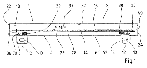
Fig. 1 is a schematic longitudinal section view of an
exemplary embodiment of a linear lamp 1 according to the
invention. Previous linear lamps in the prior art comprise a
spiral-wound filament resulting in high energy consumption.
Types of linear lamps with spiral-wound filaments are, for
example, Linestra from OSRAM, Philinea from Philips and Ralina
from Radium. Linear lamps are used, for example, in living
spaces, such as bathrooms or kitchens or as batten luminaires
in cupboards.
The linear lamp 1 from Fig. 1 has a tubular longitudinal bulb
2. This is made of glass, which, advantageously, substantially
does not experience any ageing effect due to exposure to
external or internal radiation (UV resistance). Sockets 6, 8,
which are spaced apart from each other in the longitudinal
direction of the linear lamp 1, project from an outer lateral
surface 4 of the bulb 2 or glass bulb approximately in the
same radial direction. Said sockets enable the linear lamp 1
to be used in a holder in a conventional luminaire for linear
lamps and electrically contacted. In Fig. 1, the sockets 6, 8
each comprise a recess 10 on their front and rear sides by
means of which they are gripped from behind by a corresponding
element of a holding fixture of the luminaire for mounting.
Contact lugs 12 are embodied on a lower side of the socket 6,
8 in Fig. 1 for electrical contacting. The above-described
embodiment of the linear lamp 1 preferably conforms to a
standard.
PCT/EP2010/068232 / 2009P20275WO
8
Inside the bulb 2, a longitudinal printed circuit board 14
with a plurality of light-emitting diodes or LEDs 16 (to
simplify matters, only one single LED has been given a
reference number) is used. The printed circuit board 14 is an
FR4 board, which is held by the fixing means explained below.
For better heat removal, the printed circuit board 14 can be
made of a material with good heat conductivity such as
aluminum or ceramic, at least in sections, although this does
result in higher costs. An axial length of the printed circuit
board 14 is slightly shorter than an axial length of the bulb
2 causing end sections 18, 20 of the printed circuit board 16
to be spaced apart from a respective end face 22 or 24 of the
bulb 2.
The LEDs 16 extend from a diode side 26 of the printed circuit
board 14 pointing away from the sockets 6, 8 in a fixed row
one behind the other approximately parallel to the
longitudinal direction. Electronic components or electronic
elements 30, of which two are shown by way of example in Fig.
1, for powering and controlling the LEDs 16 are disposed on a
lower side 28 of the printed circuit board 14 facing away from
the diode side 26.
Fig. 2 shows the linear lamp 1 in a schematically enlarged
cross-sectional view with a cutting plane through the plate 40
from Fig. 1. A distance between the diode side 26 of the
printed circuit board 14 and an inner lateral surface 32 of
the bulb 2 is greater than the distance between the lower side
28 and the inner lateral surface 32 of the bulb 2, wherein the
distance is in each case measured in an approximately
orthogonal direction to the printed circuit board 14. A
distance between the longitudinal edges of the printed circuit
board 14 and the inner lateral surface 32 is approximately the
PCT/EP2010/068232 / 2009P20275W0
CA 02781,
9
same and this also applies to the distance between the
transverse edges and the end faces 22, 24 from Fig. 1. A width
of the printed circuit board 14 in Fig. 2 approximately
corresponds to the width of the sockets 6, 8. Two diode rows
34, 36 extending approximately at a parallel distance to each
other are embodied on the diode side 26 of the printed circuit
board 14. The spacing apart of the diode rows 34, 36 permits
high heat transfer from the LEDs 16, see Fig. 1. It is also
conceivable, instead of two diode rows 34, 36, for there to be
only one diode row or more than two diode rows. The parallel
distance of the diode rows 34, 36 and the printed circuit
board 14, which is offset from a longitudinal axis of the bulb
2 in the direction of the sockets 6, 8, also provides large-
area illumination of the bulb 2 by the LEDs 16.
In Fig. 1, the bulb 2 is filled with helium as a filling gas
with good heat conductivity with a comparatively low filling
pressure. A low filling gas pressure is advantageous from the
point of view of production technology and results in low
costs. When the linear lamp 1 is in use, the filling gas with
good heat conductivity enables a large amount of heat to be
removed from the LEDs 16 and also from the electronic elements
30 to the bulb 2 for cooling and the bulb can release the heat
into the environment. In Fig. 1, the heat flow is indicated by
way of example by arrows 37. In addition, the large areas of
the printed circuit board 14 and of the bulb 2 provide large
heat transfer areas to the filling gas.
During the production of the linear lamp 1, the glass bulb 2
is melted around the printed circuit board 14, which is spaced
apart from the bulb 2, resulting in temperatures of
approximately 1000 C. To protect the LEDs 16 and the
electronic elements 30 from the high temperatures, heat traps
PCT/EP2010/068232 / 2009P20275W0
CA 02781,
or heat sinks made of an inexpensive copper plate 38, 40 are
disposed at the end sections 18, 20 of the printed circuit
board 14. The highest temperatures occur in these areas during
production. The design of the plates 38, 40 is described in
more detail below in Fig. 3. In addition, while the bulb 2 is
being melted around the printed circuit board 14, active air
cooling takes place - this is not explained in any further
detail. Fig. 3 shows an enlarged detail of a right end section
of the linear lamp 1 from Fig. 1 with the plate 40. This is
bent approximately at a right angle and has a holding limb 42
fixed approximately parallel to the lower side 28 of the
printed circuit board 14. A further plate limb 44 extends
upward approximately at a parallel distance from a transverse
edge 47 of the printed circuit board 16 in Fig. 3. Due to this
embodiment and arrangement, the plate 40 creates virtually no
shadowing or no shadowing at all during the use of the linear
lamp 1 and provides a large heat transfer surface to the
surrounding gas.
In addition, holding arms 52 or 54 pointing away from the
socket 6, 8 project from a respective longitudinal edge 48 and
50, see Fig. 2, of the holding limb 42 of the plate 40 in the
direction of inner lateral surface 32 of the bulb 2. The
holding arms 50 and 52 are disposed in a V shape with respect
to each other and are each supported by their end section 56
or 58 pointing away from the plate 40 on the inner lateral
surface 32 of the bulb 2. In the region of the longitudinal
edges 60, 62, see Fig. 1, of the printed circuit board 14, the
holding arms 50 and 52 are bent with a radius in such a way
that in each case an arc section 64 or 66 is formed which is
concave on its side pointing in the direction toward the
printed circuit board 14. In the transitional area from the
arc section 64 and 66 to the holding arm 50 or 52, which
PCT/EP2010/068232 / 2009220275W0
CA 02781,
11
extends substantially straight, these each lie on the
respective longitudinal edges 60, 62 of the printed circuit
board 14 and exert a locking force on the printed circuit
board 14 due to the fact that the arc sections 64, 66 function
as springs. The plate 40 is hence connected to the printed
circuit board 14 by means of the holding arms 52, 54 by a non-
positive, positive or material fit.
At a transverse edge 68 of the holding limb 42 pointing away
from the plate limb 44, there is a support arm 70 extending
from the lower side 28 of the printed circuit board 14 and
supported on the inner lateral surface 32 of the bulb 2. Since
the design of the plate 38 corresponds to that of the plate
40, the printed circuit board 14 is secured by means of the
end sections 18 and 20 of the plates 38 or 40 by means of
their respective holding arms 52, 54 and their respective
support arm 70 inside the bulb 2.
At its end section 72 pointing away from the printed circuit
board 14, the support arm 70 of the plates 38 and 40, see Fig.
3, is approximately W-shaped thus forming a V section 74
pointing toward the printed circuit board 14. This is in each
case disposed in the area of the socket 6, 8. A power supply
76 used for the contacting extending from the socket 8 in Fig.
3 to the printed circuit board 14 is guided through an opening
(not shown) in the bent area of the V section 74. Here, the
opening is designed such that, in a displacement direction
away from the printed circuit board 14, the power supply 76 is
blocked by the opening of the V section 74 and can only be
moved through the opening in the direction of the printed
circuit board 14. Hence, the V section 74 is embodied as a
type of insulating piercing connecting device. The left-hand
PCT/EP2010/068232 / 2009P20275W0
CA 02781,
12
plate 38 in Fig. 1 is embodied in the same way and so a power
supply 78 is also fixed by this.
Fig. 4 is a perspective view of the end section 20 of the
linear lamp 1 shown in Fig. 3. The end sections 56, 58 of the
holding arms 52, 54 are slightly bent so that the end sections
56, 58 lie, with an approximately convex surface, at least in
sections on the inner lateral surface 32.
The width of the support arm 70 approximately corresponds to
half the width of the transverse edge 68 of the holding limb
42. Here, the support arm 70 is approximately in the middle of
transverse edge 68. The width of the holding arms 52, 54
approximately corresponds to that of the support arm 70,
wherein these extend approximately from an end region of the
longitudinal edges 48, 50, see Fig. 2, adjacent to the
transverse edge 68.
It is conceivable for the plates 38, 40 to be embodied as SMD
components to simplify their connection to the printed circuit
board 14.
The left-hand plate 38 in Fig. 1 is embodied similarly to the
plate 40. Additionally to or instead of the plates 38, 40, the
printed circuit board 16 can comprise heat-conducting
materials, although this would entail higher costs in both
cases. In each case, heat sinks can be dispensed with in the
case of the linear lamp 1 according to the invention thus
resulting in a low weight.
Fig. 5 is a schematic view of the LED driver circuit 71 of a
linear lamp 1 according to the invention. For the power supply
for the light-emitting diodes 16, the circuit comprises two
PCT/EP2010/068232 / 2009P20275W0
CA 02781,
13
linear longitudinal controllers 72 connected in parallel
permitting a simple, flat and compact design. However, other
embodiments are also conceivable, in particular embodiments
with only one linear longitudinal controller. The arrangement
shown is also characterized by good EMV properties.
Fig. 6 is a schematic longitudinal section view of a linear
lamp according to a further exemplary embodiment. The
principal structure of the linear lamp 1 is similar to that in
Fig. 1 and has a tubular longitudinal bulb 2 made of glass.
Sockets 6, 8, which are spaced apart from each other in the
longitudinal direction of the linear lamp 1, project from an
outer lateral surface 4 of the bulb 2 or glass bulb
approximately in the same radial direction. Said sockets
enable the linear lamp 1 to be received in a holder of a
conventional luminaire suitable for linear lamps and
electrically contacted. In Fig. 1, the sockets 6, 8 each
comprise a recess 10 on their front and rear sides, by means
of which they are gripped from behind by a corresponding
element of a holding fixture of the luminaire for mounting. In
Fig. 1, contact lugs 12 are provided on a lower side of the
socket 6, 8 for electrical contacting. The above-described
embodiment of the linear lamp 1 preferably conforms to a
standard.
Similarly to Figs. 1 to 3, inside the bulb 2, a longitudinal
printed circuit board 14 with a plurality of light-emitting
diodes or LEDs 16 (to simplify matters, only one single LED
has been given a reference number) is used. An axial length of
the printed circuit board 14 is slightly shorter than an axial
length of the bulb 2 causing end sections 18, 20 of the
printed circuit board 16 to be spaced apart from a respective
end face 22 or 24 of the bulb 2.
PCT/EP2010/068232 / 2009P20275W0
CA 02781,
14
The LEDs 16 extend from a diode side 26 of the printed circuit
board 14 pointing away from the sockets 6, 8 in a fixed row
one behind the other approximately parallel to the
longitudinal direction. Electronic components or electronic
elements 30, of which two are shown by way of example in Fig.
6, for powering and controlling the LEDs 16 are disposed on a
lower side 28 of the printed circuit boards 14 facing away
from the diode side 26.
The printed circuit board 14 is fixed by means of two spacers
45 in the glass bulb 2 for which the spacer 45 is bonded to
the printed circuit board 14 and the glass bulb 2. The
electrical contacting is provided by contacting devices 49
embodied as plate bending parts. In the end region.
The bulb 2 is filled with helium as a filling gas with good
heat conductivity with a comparatively low filling pressure.
Hence, the heat flow takes place in the way indicated by way
of example by arrows 37. In addition, the large areas of the
printed circuit board 14 and of the bulb 2 provide large heat
transfer areas to the filling gas.
The production of the linear lamp 1 is performed as described
above, i.e. the glass bulb 2 is melted around the printed
circuit board 14, which is spaced apart from the bulb 2. To
protect the LEDs 16 and the electronic elements 30 from the
high temperatures, heat traps or heat sinks made of an
inexpensive copper plate 77, 48 are disposed at the end
sections 18, 20 of the printed circuit board 14. The highest
temperatures occur in these areas during production. The
plates 77, 48 are bent approximately at a right angle and have
a holding limb 42 fixed approximately parallel to the lower
PCT/EP2010/068232 / 2009220275W0
CA 02781,
side 28 of the printed circuit board 14. A plate limb 44
extends upward approximately at a parallel distance from a
transverse edge 47 of the printed circuit board 14. Due to
this embodiment and arrangement, the plates 77, 48 create
virtually no shadowing or no shadowing at all during the use
of the linear lamp 1 and provide a large heat transfer surface
to the surrounding gas.
Fig. 7 is a perspective view of the end section from Fig. 6.
The plate 77, the spacer 45 and the contacting devices 49 are
secured to the printed circuit board. The contacting device 49
comprises a bent plate with a V-shaped receiver for a contact
wire 79. The spacer 45 is formed from a U-shaped bent plate
and bonded to the bulb 2. Each of these components is a plate
bending component and can therefore advantageously be used for
heat removal. It is conceivable for the plates 77, 48 and the
spacer 45 and the contacting devices 49 to be embodied as SMD
components to simplify their connection to the printed circuit
board 14. This enables the heat to be removed from the printed
circuit board 14 particularly effectively. In this exemplary
embodiment, the width of the plates 77, 48 approximately
corresponds to the width of the printed circuit board 14 thus
permitting particularly simple handling together with good
heat removal. However, also conceivable are embodiments in
which the width of the plates 77, 48 is greater than the width
of the printed circuit board 14, which improves heat removal,
or embodiments in which the width of the plates 77, 48 is
smaller than the width of the printed circuit board 14, which
improves handling.
The left-hand plate 77 in Fig. 6 corresponds to the plate 48.
Additionally to or instead of the plates 77, 48, the printed
circuit board 14 can comprise thermally conductive materials,
PCT/EP2010/068232 / 2009220275W0
CA 02781,
16
but this would result in higher costs in both cases. In each
case, heat sinks can be dispensed in the case of the linear
lamp 1 according to the invention, thus resulting in a low
weight.
The glass bulb 2 is characterized by a more pleasing aesthetic
appearance than a plastic bulb. Coating of the bulb 2 enables
the aesthetic appearance to be further improved and the
luminous characteristics and the radiation characteristics of
the linear lamp 1 to be changed. In addition, glass has better
light transmission than plastic.
It is conceivable to embody the LEDs 16 without a housing.
In deviation from the exemplary embodiment, the LEDs 16 can be
disposed in any way desired. It is also possible to provide
different luminous colors and color temperatures (for example
multicolored linear lamps 1).
The linear lamp 1 has, for example, a lamp wattage (without a
driver) of between 4 and 5 W and a luminous flux of between
250 and 280 lm, wherein a luminous flux of this kind
corresponds to that of a conventional linear lamp with a
spiral-wound filament.
The invention discloses a linear lamp having a tubular bulb
made of glass. At least one socket is provided for the
electrical contacting and mounting of the linear lamp. At
least one light-emitting diode is disposed in the bulb as a
luminous element. It can also be advantageous for the sockets
to be disposed at one or both ends, in particular at right
angles to the main radiation direction of the glass bulb.