Note: Descriptions are shown in the official language in which they were submitted.
CA 02781502 2012-05-18
WO 2011/067738 PCT/IB2010/055577
METHOD AND PLANT FOR PRODUCING A FIBERGLASS PROFILE TO BE
USED AS REINFORCING ELEMENT FOR STRENGTHENING AN
EXCAVATION WALL
FIELD OF THE INVENTION
The present invention falls within the scope of production of reinforcing
elements
for strengthening the excavation face of a tunnel. More precisely, the present
invention relates to a fiberglass profile with greater properties of pullout
strength
than those of conventional profiles used for the same purpose. The present
invention also relates to a method for producing this fiberglass profile
through a
limited number of steps at relatively limited costs. The present invention
also
relates to a plant for implementing the method, i.e, for producing the
fiberglass
profile according to the invention.
STATE OF THE ART
As it is known in the field of strengthening tunnel excavation walls,
fiberglass
elements have been used for many years now, especially in the presence of clay
and incoherent soils. These elements can be used both to strengthen the
excavation face and also as radial nailing elements. It is also known that
fiberglass
profiles are connected to the surrounding ground by cementing. In other words,
each profile is buried in a cement mortar after having been inserted into an
appropriate pre-bore made in the wall to be strengthened. The arrangement of
the
profiles, their length and their density (i.e. number per square meter) varies
according to operating conditions. The fiberglass profiles usually have a
solid
transverse section or alternatively an axial cavity that is used for insertion
of the
cement mortar.
Figures 1 to 3 are relative to a .conventionally used fiberglass profile (10).
As
shown, the profile has an internally hollow circular section with an outer
diameter
varying, in the majority of cases, from 55 to 70 millimeters. The profile (10)
is
usually produced through a pultrusion process during which the glass fiber,
previously impregnated with a polymer base, passes through a heated die having
circular shape. With reference to Fig. 1, at the end of the pultrusion
process, the
CA 02781502 2012-05-18
WO 2011/067738 PCT/IB2010/055577
outer surface (1A) of the profile (1) is machined to improve its adhesion to
the
cement mortar. In particular, machining consists in producing a groove (2) by
removing material through milling of the profile, cutting part of the
longitudinal
fibers forming the profile, reducing the resisting cross-section thereof. As
shown,
this groove extends in a spiral in a similar manner to a thread.
With reference to Fig. 3, during installation of the profile (10) the cement
mortar (5)
is inserted between the outer surface (1A) of the profile (1) and the pre-bore
through valves or through other functionally equivalent elements. In the
specific
case of valves, these are positioned in longitudinal points of the profile.
The
cement mortar (MC) reaches the valves through pipes (not shown), which are
positioned inside the longitudinal cavity (3) of the profile (1) to
subsequently be
distributed around the relative surface (1A), also occupying the spiral groove
(2) as
clearly shown in Fig_ 3. During any tensile stress (T) on the profile, the
cement
mortar (MC) arranged in the groove (2) is subjected to a shearing action
offering
low resistance to pullout of the profile. The geometrical form of the profile
(1) in
fact causes a longitudinal interruption of the glass fibers positioned
externally.
These fibers are in practice substantially severed and therefore cannot
contribute
towards the tensile strength (TS). It has also been seen that due to the
decrease
of the resisting cross-section caused by the removal of material, fiberglass
profiles
currently used do not even offer an acceptable tensile strength.
Methods are also known wherein a metallic thread or web is wrapped around a
profile made by fiberglass fibers which are subsequently polymerized- After
the
polymerization, the metallic thread of web is removed from the profile,
leaving
thereon a negative imprint which forms the corrugation of the profile. Such
methods are described for example in prior documents JP-57-18484, EP-0667228,
EP-0733456. In these cases, the corrugation of the profile is not determined
before the polymerization of the profile, but it derives from the imprint
which is left
by the metallic thread or web which must necessarily be removed after the
polymerization process.
Therefore, the main aim of the present invention is to provide a new
fiberglass
profile and a new method for producing this profile which allows the aforesaid
drawbacks to be overcome.
CA 02781502 2012-05-18
WO 2011/067738 PCT/IB2010/055577
3
Within this aim a first object of the present invention is to provide a
fiberglass
profile which has a high pullout strength, greater than that achievable
through
conventional solutions.
Another object of the present invention is to provide a method for producing
this
fiberglass profile which includes a limited number of steps easily produced at
competitive costs.
A further object of the present invention is to provide a profile and a method
which
are reliable and relatively easily implemented at competitive costs. One more
aim
of the present invention is to provide a plant that allows implementation of
the
method according to the present invention.
SUMMARY OF THE INVENTION
The present invention therefore relates to a fiberglass profile to be used as
reinforcing element for strengthening an excavation wall, for example in the
field of
producing galleries and/or tunnels. The profile according to the invention
comprises an axially extending body formed by glass fibers anchored in a
polymer
resin through a polymerization process. The profile is characterized in that
the
outer surface has a corrugated trend, intended to indicate a substantially
undulating trend with respect to an axial cross-sectional plane of the
profile. In
particular, this corrugated trend is defined by a different degree of
compression of
the outermost fibers of the profile. In practice, according to the invention
the
outermost glass fibers are compressed at axial intervals and maintain their
integrity to maintain the resisting cross-section of the profile. It has been
seen that
the corrugated trend of the outer surface of the profile advantageously
increases
the pullout strength thereof as the cement mortar destined to surround the
profile
is subjected mainly to compression and no longer to shear, as is instead the
case
in conventional profiles.
The present invention also relates to a method for producing a fiberglass
profile
according to the present invention. The method provides for impregnation of
the
glass fibers with a polymer resin and subsequent orientation thereof according
to
an axial direction, arranging them so as to configure an axially extending
profile.
The method according to the invention provides for compression of the
outermost
CA 02781502 2012-05-18
WO 2011/067738 PCT/IB2010/055577
4
glass fibers at axial intervals so as to impart a corrugated trend to the
outer
surface of the profile, i.e. an undulating trend considered with respect to an
axial
cross-sectional plane of the profile. The profile is subsequently subjected to
a
polymerization process that anchors the structure of the profile.
According to a possible embodiment, the outermost fibers are compressed
through a thread-like compression element which can, for example, be formed of
a
thread made of polyester, glass fibers or other functionally equivalent
material.
The thread-like compression element can be removed following completion of the
polymerization process or, more preferably and advantageously, it can remain
incorporated and enclosed into the profile in the polymerization process.
According to the invention, the compression of the outermost glass fibers of
the
profile is such that the outer surface (15b) of said profile and the thread-
like
compression element have together an overall corrugated shape which is
substantially corresponding to the corrugated shape of the desired finished
profile.
In other words, the definition of the corrugated profile of the finished
profile is
already completed before the polymerization step and does not depend on the
removal of the thread-like element after the polymerization. In this way, the
entire
manufacturing process of the profile becomes much simpler and faster than the
processes of the known art.
According to a first possible embodiment of the method, the thread-like
compression element is formed by a thread with circular section and is wound
in a
spiral, preferably with constant pitch, around the profile so that the outer
surface
has a regular trend, preferably sinusoidal, with respect to an axial cross-
sectional
plane. According to an alternative embodiment, the thread-like compression
element has a concave section and is wound around the fiberglass profile
substantially with zero pitch, that is, with a a pitch which is substantially
comparable to the thickness of the thread-like element. Following compression,
the outermost glass fibers are partially arranged in the cavity defined by the
section of the thread-like element. In this manner, the corrugated trend is
defined
for the outer surface of the profile.
CA 02781502 2012-05-18
WO 2011/067738 PCT/IB2010/055577
In the method of the present invention, the corrugated profile is entirely
defined
already before the polymerization, and therefore does not depend on the
removal
of the thread-like compression element after the polymerization.
The present invention also relates to a plant for implementing a method
according
5 to the present invention- The plant according to the invention comprises an
impregnation tank containing a polymer resin through which the glass fibers
are
impregnated. The plant also comprises means for orientation and arrangement of
the glass fibers so as to allow an orientation in axial direction of the
fibers and an
arrangement that configures an axial profile. The plant also comprises
compression means to compress the outermost glass fibers of the profile at
axial
intervals so as to impart a corrugated trend to the surface. In particular,
these
compression means are operatively positioned upstream of appropriate
polymerization means through which the polymerization process that anchors the
glass fibers in the polymer resin is activated.
BRIEF DESCRIPTION OF FIGURES
Further features and advantages of the present invention shall be apparent
from
the description of embodiments of a profile according to the present invention
and
of a relative method and plant for producing this profile, shown by way of non-
limiting example in the accompanying drawings, wherein:
Fig. I is a side view of a portion of a profile in composite material
currently
used;
- Fig. 2 is a side view of the profile of Fig_ 1;
Fig. 3 is a view relative to an application of the profile of Figs .1 and 2;
- Fig. 4 is a longitudinal sectional view of a portion of a first embodiment
of a
profile according to the present invention;
Fig. 5 is a further sectional view according to the line IV-IV of Fig. 4;
Fig. 6 is a view relative to an application of the profile of Fig. 4;
Fig. 7 is a longitudinal sectional view of a portion of a second embodiment
of a profile according to the present invention;
Fig. 8 is a cross-sectional view of the profile of Fig. 7;
CA 02781502 2012-05-18
WO 2011/067738 PCT/IB2010/055577
6
Fig. 9 is a view of a further embodiment of a profile according to the present
invention;
- Fig. 10 is a schematic diagram of a plant for producing a profile according
to the present invention.
DETAILED DESCRIPTION
The profile according to the present invention is indicated hereunder with the
reference number 15. This profile 15 has an axially extending body formed of
glass fibers 15A, 15B aligned according to an axial direction X. More
precisely, the
glass fibers 15A, 15B are anchored in a polymer resin, preferably polyester,
through a polymerization process. According to the invention, the outer
surface
15B of the body 15 is compressed at longitudinal intervals so as to have a
corrugated trend, i.e. a substantially undulating trend with respect to an
axial
cross-sectional plane of the profile 15, i.e. with respect to a cross-
sectional plane
containing the longitudinal axis. The corrugated trend of the surface 15B is
defined
by a different degree of compression of the outermost glass fibers 5B which
are
substantially compressed at axial intervals. More precisely, "compression" is
intended as a crushing in substantially radial direction of the outer fibers
5B so that
the outer surface 15B is formed by more compressed portions alternated with
less
compressed portions. The expression "radial direction" indicates a transverse
direction substantially orthogonal to the axial direction X.
Fig. 4 is a sectional view relative to a portion of a profile 15 according to
the
present invention. Fig. 5 is instead a section produced along an axial cross-
sectional plane and allows observation of the arrangement of the fibers 5A, 5B
forming the profile 15. As evident, the innermost fibers 5A of the profile 15
are
aligned parallel to the axial direction X and have an integral and continuous
trend
without longitudinal interruptions. The outermost fibers 5B are instead
compressed
at axial intervals, but without having longitudinal interruptions. In
particular,
compression of the outermost fibers 5B defines portions of the profile 15 at
which
it has a radial extension D1 and other portions in which it has a radial
extension
D2. The continuity of the outermost fibers 15B advantageously increases the
tensile strength of the profile with respect to the strength offered by a
conventional
CA 02781502 2012-05-18
WO 2011/067738 PCT/IB2010/055577
7
profile, such as the one shown in Fig. 1. In other words, unlike the
conventional
solutions, the outermost fibers 5B of the profile 15 are not longitudinally
interrupted
or severed, but are only compressed.
Fig. 6 is a view relative to a possible application of the profile 15. More
precisely,
this figure refers to a possible installation of the profile 15 inserted in a
pre-bore
produced in an excavation wall to be strengthened. The volume of space between
the profile 15 and the surface 19 of the pre-bore is filled with cement mortar
MC.
The external structure of the surface 15B ensures that, during application of
tensile
stress T on the profile 15, the cement mortar MC is mainly subjected to
compressive stresses (indicated by the arrows with reference C) and not to
shear
stresses as occurs in conventional solutions (see Fig. 3). Through the cement
mortar, these compressive stresses are transferred directly to the internal
wall of
the pre-bore. Consequently, the pullout strength of the profile 15 is
advantageously increased as cement mortars MC on the one hand have excellent
compressive strength properties and on the other hand they transfer
compressive
stresses to the surrounding ground. Laboratory tests have shown that with the
same section and radial dimension, the pullout strength of the profile 15
according
to the invention is over 40% greater than that of conventional profiles having
the
structure shown in Figs. I to 3. Pullout strength is intended in practice as
the
tensile stress T which must be applied to the profile in order to pull it out
of a
containment wall in which it has previously been cemented.
With reference once again to Fig. 4, it can be observed that the outer surface
15B
of the profile 15 has quite a regularly corrugated trend and precisely a
substantially
sinusoidal trend with respect to an axial cross-sectional plane. More
precisely, the
outer surface 15B preferably has a concave portion 16 (in practice wishing to
indicate a more compressed portion) and a convex portion 17 (i.e. a less
compressed portion) which extend in a spiral alternating in axial direction X.
As
better specified hereunder, this structure can be obtained, for example, by
winding
a thread-like compression element 8 in a spiral with a constant spiral pitch,
during
formation of the profile 15 and in particular before the polymerization
process
through which the glass fibers 5A, 5B are anchored to the polymer resin. Figs.
7 to
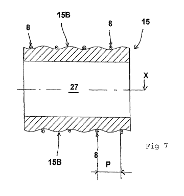
9 are relative to a second embodiment of the profile 15 according to the
present
CA 02781502 2012-05-18
WO 2011/067738 PCT/IB2010/055577
8
invention which differs to the one in Figs_ 4 to 6 due to the different
transverse
section of the profile 15, in which the term "transverse" indicates a section
according to a plane substantially orthogonal to the axial direction X. In
this
second solution, the profile 15 has a cavity 27 with a substantially circular
section
which extends axially preferably for the entire length of the profile. This
cavity 27
has the function of allowing the passage of pipes (not shown) conveying the
cement mortar MC.
In this regard, Fig. 9 shows a second portion of a profile 15 relative to this
second
embodiment. More precisely, this second portion comprises a first part 21A and
a
second part 21B which have an outer surface 15B corresponding to the one
shown in Figs_ 7 and 8. An intermediate part 22 is defined between the two
parts
21A, 21B for positioning of feed valves (not shown) of the mortar MC that is
conveyed to these valves through the pipes (not shown) positioned operatively
along the axial cavity 17. As shown, the intermediate part 22 has a
substantially
cylindrical outer surface, i.e. which does not have a corrugated trend
characteristic
of the other parts of the profile 15_ A radial passage 19 is provided to allow
the
mortar MC to pass from the inside of the axial cavity 27 to the outside of the
profile
15.
The present invention also relates to a method for producing a profile
according to
the present invention- More precisely, the method can be used both to produce
a
profile with solid section, such as the one shown in Figs. 4 to 6, and a
profile
provided with an axial cavity 27, such as the one relative to Figs. 7 to 9.
The method according to the invention provides for impregnation of the glass
fibers 5A, 5B with a polymer resin, preferably polyester. The fibers 5A, 5B
are
oriented, preferably under the action of tensile stress, according to an axial
direction X and are mutually arranged so as to configure a profile 15
extending
substantially axially. The method according to the invention therefore
provides for
compression of the outermost glass fibers 5B of the profile 15 at axial
intervals so
as to impart a corrugated trend to the outer surface 15B, wishing to indicate
a
substantially undulating trend with respect to an axial cross-sectional plane,
such
as the plane IV-IV indicated in Fig. 4. Axial cross-sectional plane is
intended in
CA 02781502 2012-05-18
WO 2011/067738 PCT/IB2010/055577
9
substance as a plane belonging to the bundle of planes having the axis X as
center.
More precisely, this compression of the outer surface 15B, is implemented
during
traction and therefore axial advance of the profile 15. Subsequently, the
profile 15
is subjected to a polymerization process through which the glass fibers 5A, 5B
of
which the profile is composed are anchored in position and shape in the
polymer
resin.
Unlike conventional pultrusion processes, the final shape of the profile 15 is
therefore established before and not after the polymerization step . In
particular,
the undulating shape of the outer surface 15B is imparted through a
compression
of the outermost fibers 5B without any longitudinal interruption thereof. In
other
words, the outer fibers 5B maintain an integral and continuous structure for
their
entire relative longitudinal extension.
Therefore the undulating shape of the outer surface 15B does not depend on
whether the compression element which is used before the polymerization to
compress the fibers is removed or not, so that it can advantageously remain
incorporated to the profile even after the polymerization so as to constitute
an
integral part thereof.
According to a possible preferred embodiment of the invention, the outermost
glass fibers 5B are radially compressed through a thread-like compression
element 8 (shown in Fig. 7) which is wound in a spiral around the outer
surface
156 of the profile 15. The expression "thread-like compression element"
generically indicates an element which can be wound around the profile in the
same way as a thread, a tape or other similar articles so as to generate a
compressing action. The thread-like compression element can be made of metal
or non-metallic material. In the second case, it could be made, for example,
of
polyester or glass fibers. Other types of material could nonetheless be used.
Moreover, the thread-like compression element can have a circular transverse
section (as in the case of a thread) shaped or alternatively also polygonal.
According to a first embodiment of the method according to the invention, the
thread-like element 8 is in the form of a thread with a solid circular section
and is
wound with a substantially constant spiral pitch P so that the outer surface
15B
CA 02781502 2012-05-18
WO 2011/067738 PCT/IB2010/055577
has a regular trend along substantially the entire longitudinal extension, as
can be
seen in Fig. 7. This thread remains wound around the profile 15 during the
polymerization process thereof in order to maintain the undulating structure
imparted to the outer surface 15B. Through the polymerization process, the
glass
S fibers 5A, 5B are anchored permanently in the polymer resin, in practice
occupying
the position previously imposed by the tension of the thread-like compression
element 8. At the end of the polymerization process, the thread-like
compression
element 8 can be separated from the outer surface 15B, but more advantageously
it remains incorporated to the polymerized profile.
10 According to a further embodiment of the method according to the invention,
the
thread-like compression element 8 has a concave transverse section, for
example
semi-circular, and is wound around the profile 15 with substantially zero
spiral
pitch, that is, substantially comparable to the thickness of the thread-like
element-
In particular, the thread-like element 8 is wound so that the semi-
circumference is
facing the outer fibers of the profile 15. Following this winding and
subsequent
polymerization, the outermost glass fibers 5B are partially arranged in the
semi-
circumferential concavity so as to define the corrugated trend for the outer
surface
15B of the profile 15. At the end of the polymerization process the thread-
like
element 8 can be separated from the profile 15 so as to "free" the outer
surface
15B or, more preferably, it can remain incorporated into the polymerized
profile, so
as to render the process even simpler and cheaper.
The method according to the invention thus also allows a profile with hollow
axial
section as shown in Figs. 7 and 8 to be obtained. In this case the method
provides
for the use of a cylindrical core around which the longitudinal fibers 5A, 5B
are
oriented and arranged before compression of the outermost fibers 5B, i.e.
before
the polymerization process. The diameter of the cylindrical core in practice
establishes the diameter Di of the axial cavity 27 of the profile 15 (Fig. 9).
From the operational viewpoint, once the glass fibers 5A, 5B are impregnated,
they are oriented according to the axial direction X and arranged around the
cylindrical core (not shown). Subsequently, the outermost fibers 5B are
compressed, preferably through spiral winding of the thread-like element 8 as
described above. In this manner, the profile 15 extends coaxially to the
cylindrical
CA 02781502 2012-05-18
WO 2011/067738 PCT/IB2010/055577
11
core which can also offer advantageous support to the axial movement of the
profile. Subsequent to the polymerization process and to any separation of the
thread-like compression element 8 from the profile 15, the latter is removed
from
the cylindrical core to allow subsequent use thereof.
The method according to the invention can also be used to obtain the
configuration of the profile shown in Fig. 9 for which an intermediate portion
22 is
provided between two parts 21A, 21 B having an undulating outer surface 15B.
In
particular, this intermediate portion 22 has a cylindrical or in any case non-
undulating outer surface 22B. In order to obtain this surface, the method once
again allows the use of a thread-like compression element 8 in the form of a
thread with a solid circular section which is wound around the fiber 5A, 5B
with a
substantially zero winding pitch, that is substantially comparable to the
thickness
of the thread-like element itself, for the length LI of the intermediate
portion 22.
The present invention also relates to a plant 100 for producing a profile 15
made of
glass fibers 5A, 56 according to the present invention. In this regard, Fig.
10 is a
schematic view relative to a plant 100 through which the method for producing
a
fiberglass profile 15 can be implemented according to what is indicated above-
The plant according to the invention 100 comprises an impregnation tank 5
containing a polymer resin with which the glass fibers 5A, 5B destined to form
the
profile 15 are impregnated. In particular, due to their diameter (in the order
of tens
of millimeter) the glass fibers 5A, 5B are collected in filaments 14 before
reaching
the impregnation tank 5. Each of these filaments 14 is in practice composed of
a
group of glass fibers. The filaments are predisposed in feed reels 50 which
feed
the plant 100.
This plant comprises orientation and arrangement means 51, 52 to orient the
filaments 14 of glass fibers 5A, 56 according to an axial direction X so as to
configure an axially extending profile 15_ The plant 100 also comprises
pulling
means 60 to pull the profile 15 along a pulling direction substantially
parallel to the
axial direction X. Through the pulling means 60, the profile 15 made of glass
fibers
5A, 5B is advantageously produced according to a "continuous" process.
The plant 100 also comprises polymerization means 66 predisposed to activate
the polymerization process to anchor the structure of the profile 15. In
particular,
CA 02781502 2012-05-18
WO 2011/067738 PCT/IB2010/055577
12
these polymerization means 66, in substance formed by a polymerization oven
66B, are configured to heat the profile 15 to the correct polymerization
temperature. This heating takes place through the passage of the profile 15 in
the
polymerization oven 66B due to the pulling imparted by the pulling means 60
positioned downstream of the oven.
The plant 100 according to the invention is characterized in that it comprises
compression means 80 of the outermost fibers 5B of the profile 15. These means
are positioned between the impregnation tank 5 and the polymerization oven 66.
The compression means 80 act on the outermost fibers 5B of the profile so as
to
shape the outer surface 15B of the profile 15 according to the configuration
and
the objects described above. These compression means 80 preferably comprise a
winding unit 70 through which a thread-like compression element 8 is wound
around the surface 15B of the profile 15. The winding unit 70 is regulated so
that
winding of this thread-like element 8 takes place according to a substantially
spiral
trend with a constant pitch P, Operation of the winding unit 70, in terms of
winding
speed, is regulated as a function of the pulling speed of the profile 15 by
the
pulling means 60. In practice, extension of the spiral pitch P is defined by
combining the feed speed of the profile 15 with the winding speed of the
thread-
like compression element 8. Through this regulation it is possible, for
example, to
obtain the structure of the profile 15 shown in Fig. 9. In this regard, to
produce the
non-undulating surface 22B of the intermediate portion 22 the pulling speed is
reduced and the winding speed of the thread-like compression element 8 is
increased (or at most remains unchanged). In this manner the thread can wind
with a spiral pitch substantially close to zero so that the outer fibers 5B
are
compressed to the diameter DC indicated in Fig. 9.
The pulling speed of the profile 15 is regulated through an encoder 75 or
functionally equivalent means. The pulling means 60 can be those normally used
in conventional pultrusion processes, such as a pair of pulling belts 60B
arranged
on opposite sides of the profile 15 to exert thereon a combined and balanced
traction action.
With reference to the case above, it is observed that in the case in which a
thread-
like compression element 8 with concave transverse section is used, wound with
CA 02781502 2012-05-18
WO 2011/067738 PCT/IB2010/055577
13
substantially zero spiral pitch, then the polymerization means 66 can also
comprise a heated die (or mold) of the type normally used in conventional
pultrusion processes.
With reference to the schematic view of Fig. 10, in a possible embodiment the
orientation and arrangement means 51, 52 of the glass fibers 5A, 5B comprise a
first guide element 51 and a second guide element 52 arranged respectively
downstream of the impregnation tank 5 and upstream of the polymerization oven
668. In particular, the first guide element 51 has the function of placing the
filaments 14, composed of glass fibers, under tension and of orienting them
towards the second guide element 52. In a possible embodiment the first guide
element 51 is formed by a plate provided with holes through which the
filaments
14 are made to pass. In particular, this plate also performs a skimming
function in
order to eliminate any excess resin collected by the filaments 14 in the
impregnation tank 5.
As indicated above, the second guide element 52 is operatively positioned
upstream of the polymerization oven 66B and immediately downstream of the
compression means 80 through which the thread-like compression element 8 is
wound around the profile 15. In this regard, it is observed that the
longitudinal
distance L between the first 51 and the second guide element 52 is selected so
that the filaments 14 are already substantially oriented according to the
axial
direction X or according to the pulling direction. From a constructional
viewpoint,
the second guide element 52 can be composed of a cylinder through which the
profile 15 is made to pass so as to continue to guide it towards the
polymerization
oven 66B.
In order to obtain the fiberglass profile shown in Figs. 7 to 9, the plant
according to
the invention can be provided with a cylindrical core to support and pull the
profile
15. In accordance with what is indicated above in relation to the method of
embodiment, in this case the filaments 14 made of glass fibers 5A, 5B are
arranged around the preferably metallic cylindrical core, the main function of
which
is substantially to define the axial cavity 27 of the profile 15. However, the
cylindrical core also has the function of allowing pulling of the profile 15
during the
initial forming step thereof. In practice, the pulling means 60 initially pull
the
CA 02781502 2012-05-18
WO 2011/067738 PCT/IB2010/055577
14
cylindrical core in axial direction X to then perform their traction action
directly on
the profile 15.
Again with reference to the schematic diagram of Fig_ 10, removal means 72 of
the
thread-like compression element 8 are operatively positioned downstream of the
polymerization oven 66B. These means are configured so as to separate the
thread-like element 8 continuously during pulling of the profile along the
pulling
direction.
In a preferred variation, the plant has no removal means 72, because the
thread-
like element 8 can advantageously remain incorporated to the profile after its
polymerization.
The technical solutions adopted for the profile and for the method and the
plant for
producing said profile allow the aim and the aforesaid objects to be fully
achieved.
In particular, the profile according to the invention has a greater pullout
strength
than that of conventional technical solutions. The method according to the
invention allows the profile to be produced through a limited number of
operations
and with competitive costs with respect to the processes conventionally used.
The profile, the method and the plant thus conceived are susceptible to
numerous
modifications and variants, all failing within the scope of the inventive
concept;
moreover all details can be replaced by other technically equivalent details.
In practice, the materials used and the contingent dimensions and forms can be
any, according to requirements and to the state of the art.