Note: Descriptions are shown in the official language in which they were submitted.
WO 2011/066452 Page 1 PCT/US2010/058092
SECURELY SHARING DESIGN RENDERINGS
OVER A NETWORK
BACKGROUND OF THE INVENTION
The Field of the Invention
The present invention relates generally to computer-aided design or drafting
software.
Background and Relevant Art
Many industries use computer-aided design ("CAD") software (such as
AutoCAD, Revit, 3DS Max, SketchUp) to design and create three-dimensional
computer models. Increasingly, users of conventional design software utilize
this
software to display three-dimensional models to clients, investors, and other
individuals. The conventional focus of many conventional design software
programs
is on designing and creating three-dimensional computer models, and not on
displaying, navigating, and sharing the three-dimensional models. As such,
some
conventional design software programs make displaying, navigating, and sharing
the
three-dimensional models difficult, inefficient, or ineffective.
For example, some conventional design software may render three-
dimensional models for display that do not have a realistic appearance. In
particular,
the version of the three-dimensional model rendered by the conventional design
software may not incorporate the full details of the three-dimensional model.
For
example, the rendered version of the model may not include details such as
shading,
color, finish, and transparency. Conventional design software that is able to
create a
realistic appearance by rendering and displaying sufficient details of a three-
dimensional model can tend to require an excessive amount of computing power
and
time to display and navigate.
In addition, the navigational control tools that some conventional design
software programs use to view three-dimensional models may not be natural or
intuitive. The absence of intuitive navigational control tools in some
conventional
design software can make viewing and appreciating all aspects of a three-
dimensional
design difficult or time consuming. One will appreciate that the lack
intuitive
navigational control tools can make it particularly difficult for a person
unfamiliar
WO 2011/066452 Page 2 PCT/US2010/058092
with the software (i.e., clients, investors) to navigate a three-dimensional
model
quickly and effectively.
Conventional design software can also have limited ability to share three-
dimensional models with individuals that are not in the same location as the
designer.
For example, some conventional design software requires the designer to save
or
export the model into a file and send file (e.g., by email) to a desired
viewer. The size
alone of some three-dimensional model files can make transferring and sharing
of the
model difficult.
Additionally, in order to open and view the three-dimensional model file, the
viewer is often required to own and have installed on his or her computer the
same
software as the designer. Often, it is not practical for all desired viewers
of a
particular design to have the same design software. This is due, in part, to
the fact
that conventional design software can be rather expensive, the viewer may not
be in
the design business, or the viewer simply prefers a brand of design software
that is not
the same as the designer's.
Furthermore, even in the event that the desired viewer has the same design
software as the designer, the designer may not want to provide others with a
digital
copy of the three-dimensional model. For instance, when sharing a three-
dimensional
model using some conventional design software, the saved or exported computer
design file can contain the visual aspects of the design as well as
proprietary data
concerning the design. One will appreciate that sharing all of the data
associated with
a three-dimensional model can be undesirable because the data could easily be
misappropriated by a viewer. Moreover, the viewer may also have the ability to
make
edits to the design data, thereby changing the design and the designer's
original intent.
In order to avoid the security risks associated with conventional design
software, including those identified above, many designers resort to simply
capturing
a limited number of selected static views of a three-dimensional model. In
some
cases, these views can be combined into a video file. The designers might then
provide copies of the static views or the video file, either electronically or
by hard
copy, to the desired viewers. While sharing static images or a video of a
three-
dimensional model may resolve some of the complications and risks associated
with
conventional design software, there can be drawbacks with sharing only certain
views
of a three-dimensional model. For example, the viewer cannot navigate through
the
WO 2011/066452 Page 3 PCT/US2010/058092
three-dimensional model and see all of the different angles and lines that
would be
possible with a three-dimensional computer model.
According, there are a number of problems in the art that can be addressed.
BRIEF SUMMARY OF THE INVENTION
Implementations of the present invention overcome one or more problems in
the art with systems, methods, and apparatus configured to allow easy and
efficient
rendering, displaying, navigation, and/or sharing of computer generated
designs and
models. In particular, one or more implementations of the present invention
provide
the ability to capture the geometry and the graphical attributes of a three-
dimensional
model. One or more implementations also allow for easy and intuitive
navigation of
the captured geometry. Additionally, one or more implementations allow a user
to
share the geometry and the graphical attributes of a three-dimensional model
without
sharing the source file or proprietary details of the source file.
Furthermore, one or
more implementations can allow for sharing of the geometry and graphical
attributes
of a three-dimensional model without requiring the viewer to have the software
used
to create the three-dimensional model.
For example, a computer program storage product can have computer-
executable instructions stored thereon that, when executed, cause one or more
processors to perform acts of identifying one or more files corresponding to a
three-
dimensional computer model created by a design software application and stored
within a database associated with the design software application. The acts
can
additionally involve identifying geometry data and graphical aspect data of
the three-
dimensional computer model in the one or more files. Additionally, the acts
can
involve extracting the geometry data and graphical aspect data from the one or
more
files corresponding to the three-dimensional computer model. Also, the acts
can
involve storing the geometry data and graphical aspect data in a storage
module
unassociated with the design software application. Furthermore, the acts can
involve
providing an accurate three-dimensional view of the geometry and graphical
aspects
of the three-dimensional computer model at a display device using a capture
and
render software application unassociated with the design software application.
Additionally, a method from the perspective of a web server can involve
receiving, from a first remote client computer system, geometry data and
graphical
aspect data extracted from a three-dimensional computer model created using a
design
WO 2011/066452 Page 4 PCT/US2010/058092
software application. The method can also involve storing the geometry data
and
graphical aspect data in one or more geometric computer model files at a web
server.
Furthermore, the method can involve receiving one or more requests for the one
or
more geometric computer model files from a second remote client computer
system.
Also, the method can involve sending the one or more geometric computer model
files and one or more viewer application files from the web server to the
second
remote client computer system. The one or more viewer application files can be
configured to launch a temporary viewer application on the second remote
client
computer system. The temporary viewer application is configured to display the
geometry data and graphical aspect data of the one or more geometric computer
model files.
In addition to the foregoing, a method from the perspective of a client
computer system can involve sending one or more requests to a web server for
one or
more geometric computer model files comprising geometry data and graphical
aspect
data extracted from a three-dimensional computer model created using a design
software application. Also, the method can involve opening a temporary viewer
application hosted by the web server. The method can additionally involve
receiving
the one or more geometric computer model files from the web server.
Furthermore,
the method can involve displaying an accurate three-dimensional view of the
geometry and graphical aspects of the three-dimensional computer model at a
display
device using the temporary viewer application
This Summary is provided to introduce a selection of concepts in a simplified
form that are further described below in the Detailed Description. This
Summary is
not intended to identify key features or essential features of the claimed
subject
matter, nor is it intended to be used as an aid in determining the scope of
the claimed
subject matter.
Additional features and advantages of the invention will be set forth in the
description which follows, and in part will be obvious from the description,
or may be
learned by the practice of the invention. The features and advantages of the
invention
may be realized and obtained by means of the instruments and combinations
particularly pointed out in the appended claims. These and other features of
the
present invention will become more fully apparent from the following
description and
WO 2011/066452 Page 5 PCT/US2010/058092
appended claims, or may be learned by the practice of the invention as set
forth
hereinafter.
BRIEF DESCRIPTION OF THE DRAWINGS
In order to describe the manner in which the above-recited and other
advantages and features of the invention can be obtained, a more particular
description of the invention briefly described above will be rendered by
reference to
specific embodiments thereof which are illustrated in the appended drawings.
It
should be noted that the figures are not drawn to scale, and that elements of
similar
structure or function are generally represented by like reference numerals for
illustrative purposes throughout the figures. Understanding that these
drawings depict
only typical embodiments of the invention and are not therefore to be
considered to be
limiting of its scope, the invention will be described and explained with
additional
specificity and detail through the use of the accompanying drawings in which:
Figure 1 illustrates a schematic diagram of a computer model within an
interface of an exemplary design software application with which an
implementation
of the present invention can integrate to capture the geometry of the computer
model;
Figure 2 illustrates a schematic diagram of an interface within which a
geometric computer model, which includes the geometry and graphical aspects of
the
computer model of Figure 1, is displayed in accordance with an implementation
of the
present invention;
Figure 3 illustrates a schematic diagram of the interface of Figure 2 and
illustrates exemplary controls for navigating the geometric computer model
within the
interface in accordance with an implementation of the present invention;
Figure 4 illustrates a schematic diagram of an interface for creating a guided
tour of a geometric computer model in accordance with an implementation of the
present invention;
Figure 5 illustrates a schematic diagram of an interface for publishing a
graphic computer model in accordance with an implementation of the present
invention;
Figure 6 illustrates a schematic diagram of an interface for sharing a graphic
computer model in accordance with an implementation of the present invention;
WO 2011/066452 Page 6 PCT/US2010/058092
Figure 7 illustrates a schematic diagram of a viewer interface within which
the
geometric computer model of Figure 2 is displayed in accordance with an
implementation of the present invention;
Figure 8 illustrates an architectural schematic diagram of a system for
capturing and sharing a geometric computer model in accordance with an
implementation of the present invention;
Figure 9 illustrates a flowchart of a series of acts in a method in accordance
with an implementation of the present invention of capturing the geometry and
graphical aspects of a computer model; and
Figure 10 illustrates a flowchart of methods from the perspective of client
computer systems and of a web server in accordance with an implementation of
the
present invention for capturing and securely sharing the geometry and
graphical
aspects of a computer model.
DETAILED DESCRIPTION OF THE PREFERRED EMBODIMENTS
Implementations of the present invention extend to systems, methods, and
apparatus configured to allow easy and efficient rendering, displaying,
navigation,
and/or sharing of computer generated designs and models. In particular, one or
more
implementations of the present invention provide the ability to capture the
geometry
and the graphical attributes of a three-dimensional model. One or more
implementations also allow for easy and intuitive navigation of the captured
geometry. Additionally, one or more implementations allow a user to share the
geometry and the graphical attributes of a three-dimensional model without
sharing
the source file or proprietary details of the source file. Furthermore, one or
more
implementations can allow for sharing of the geometry and graphical attributes
of a
three-dimensional model without requiring the viewer to have the software used
to
create the three-dimensional model.
For example, at least one implementation relates to capturing the geometry
and the graphical attributes of a three-dimensional computer model created
using a
design software application, such as, for example, REVIT, AUTOCAD, SKETCHUP,
3DS MAX ("design software"). The systems, software, and methods of the present
invention can store the geometry and graphical aspects of the computer model
as a
geometric computer model file. In one or more implementations, the geometric
computer model can include only the geometry and graphical aspects of the
computer
WO 2011/066452 Page 7 PCT/US2010/058092
model. In other words, the geometric computer model may not include
dimensional
information, part information, or other work product information associated
with the
original computer model. Thus, as used herein, the term "geometric computer
model
file" refers to a computer file containing substantially only the geometry and
graphical
aspects of a three-dimensional computer model created using design software,
such as
those mentioned above.
Once captured, the designer (as well as another user/viewer discussed
hereinafter) can use a viewer application to explore the three-dimensional
geometric
computer model in a dynamically rendered virtual reality environment. The
rendering
techniques, in addition to the viewer interface, can allow the designer (or
other user)
to easily and effectively display and navigate the three-dimensional design.
As
explained in greater detail below, both the configuration of the geometric
computer
model and the viewer application can allow for seamless, intuitive navigation
of a
geometric computer model without requiring excessive computing power.
In addition, one or more implementations of the present invention allow the
designer to securely share the geometric computer model over a network (such
as a
LAN, WAN, intranet, or the internet, etc.). For instance, implementations of
the
present invention can allow a designer to automatically publish the geometric
computer model in a way that it is accessible by others through the network.
Furthermore, implementations of the present invention can provide a temporary
viewer application to allow for the display and navigation of the geometric
computer
model without requiring the design software used to create the original
computer
model. As used herein, a "temporary viewer application" refers to a viewer
application unassociated with the design software used to create the original
three-
dimensional model, which is automatically installed and removed from a
viewer's
computer to allow secure viewing of captured geometry.
Although the viewer application can display and allow a viewer to navigate
and explore the rendered geometric computer model, it is important to note
that, in at
least one implementation, the viewer application cannot change the three-
dimensional
model. Moreover, in such an implementation, the viewer does not have the
original
design file, which can contain proprietary and work product information the
designer
does not want to share with the viewer. Thus, one or more implementations can
protect the designer's work product and intellectual property by making the
work
WO 2011/066452 Page 8 PCT/US2010/058092
product otherwise inaccessible to the other users/viewers to whom the designer
shares
the model. This, in turn, enables the designer to freely share and show other
viewers
the three-dimensional model without fear they will misappropriate the design.
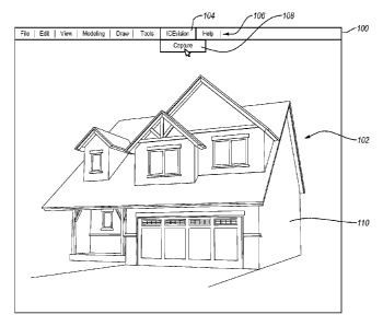
Referring now to the Figures, Figure 1 depicts a schematic diagram of a three-
dimensional computer model of a house 102 within an interface 100 of an
exemplary
design software application. As indicated above, some design software
applications
provide limited visualization and navigation capabilities without requiring
large
computing resources. For example, Figure 1 shows a three-dimensional house
rendering 102 that is displayed without shading, color, or other design
details due to
the fact that including such details may require excessive computer resources.
As mentioned above, implementations of the present invention can allow the
designer to capture the geometry and graphical attributes of a three-
dimensional
computer model in a format that allows for efficient and effective display. In
particular, one or more implementations provide a software plug- in configured
to
interact with the design software. The software plug-in can create an
additional menu
item or items in the design software. For example, Figure 1 illustrates an
additional
menu item 104 within a tool bar 106 of the design software interface 100.
In one implementation, the menu item 104 created by the software plug-in can
provide a drop-down selection that provides the designer with one or more
options
relating to the capture and rendering of the three-dimensional design. For
example,
the menu item 104 can include a selectable capture function that initiates the
capture
and/or rendering of the three-dimensional design. Additionally, the menu item
can
include other selectable functions such as "Link," which can initiate a bridge
between
the design software and the capture and render software application. The
bridge can
allow the capture and render software application to capture the geometry and
graphical aspects from a three-dimensional computer model created by the
design
software.
An end user or designer can obtain the software plug-in described above
through a variety of means. For example, the designer can download and/or
install
the software plug-in from an online source, such as a website. Of course, the
designer
can also install the software plug-in can from any other traditional means,
such as a
CD-ROM, a portable memory device, file sharing, etc. Moreover, the software
plug-
in can integrate with most, if not all, design software, including, but not
limited to,
WO 2011/066452 Page 9 PCT/US2010/058092
those mentioned above. One will appreciate that the plug-in provided can be
based
upon the particular type of design software. Thus, the plug-in for REVIT can
be
different than the plug-in for 3DS MAX, etc.
Once the designer has installed the software plug-in on the designer's
computer system, the designer can then capture a three-dimensional design in a
format that allows for efficient and effective display. In one implementation
of the
invention, for example, the designer can first open the three-dimensional
computer
model 102 in an interface 100 of the design software used to create the
design. The
designer can then select the menu item 104 from the menu bar 106 that was
added
upon installing the software plug-in, and select a function. For example, the
designer
can select the "Capture" function 108, as shown in Figure 1. Of course, in
other
implementations of the invention, the designer need not open the three-
dimensional
computer model 102; rather, the designer can select the three-dimensional
computer
model 102 based on the file name from a directory.
Upon selection of the "Capture" function 108, a capture and render software
application can automatically open. The capture and render software
application can
then automatically capture the three-dimensional geometry and graphical
aspects of
the three-dimensional computer model 102 into a geometric computer model.
Furthermore, the capture and render software application can render the
geometric
computer model into a virtual format, and display the geometric computer model
in a
viewer interface, as explained in greater detail below.
More specifically, in at least one implementation upon selection of the
"Capture" function, the plug-in can send a request to a server (web-based or
otherwise) for the capture and render software application. Upon receiving the
request, the server can send the capture and render software application to
the
designer's computer system. For example, the server can send one or more Java
application files or other executable instructions. Upon receipt of the
application
files, the designer's computer system can extract and launch the capture and
render
software application.
Thus, in at least one implementation, the capture and render software
application can be hosted on a web server. In such implementations, at least
the first
time a designer selects the "Capture" function 108 during a session, the web
server
can send the capture and render software application to the designer's
computer
WO 2011/066452 Page 10 PCT/US2010/058092
system. Upon receipt of the capture and render software application from the
web
server, the designer's computer system can launch the capture and render
software
application. One will appreciate in light of the disclosure herein that
hosting the
capture and render software application on a web server can ensure that the
designer
has the latest version of the capture and render software application each
time the
designer seeks to capture a three-dimensional computer model 102.
In an alternative implementation, the capture and render software application
can be stored directly on the designer's computer system. In such
implementations,
the designer's computer system can launch the capture and render software
application directly without requiring files from the web server. In yet
further
implementations, the capture and render software application and/or plug-in
can
require connection with, and instruction from, the web server in order to
launch the
capture and render software application, irrespective of whether the capture
and
render software application is stored locally on the designer's computer
system or on
the web server.
In any event, once the designer selects the "Capture" feature 108, the
designer's computer system can launch the capture and render software
application, if
the designer has not already opened the capture and render software
application.
Once the capture and render software application has launched, the capture and
render
software application can capture the geometry and graphical aspects of the
three-
dimensional computer model 102. For example, in one implementation the capture
and render software application automatically sends an export command to the
design
software application. The design software application then exports the file(s)
comprising the three-dimensional computer model 102. The capture and render
software application then imports the file(s) comprising the three-dimensional
computer model 102. During, or after, the importation of the file(s)
comprising the
three-dimensional computer model 102, the capture and render software
application
can parse the file(s) and save only the data necessary to recreate the
geometry and
graphical aspects of the three-dimensional computer model 102. In alternative
implementations, the capture and render software application can run through
the
database of the design software and extract and save only the data necessary
to
recreate the geometry and graphical aspects of the three-dimensional computer
model
WO 2011/066452 Page 11 PCT/US2010/058092
102. Additionally, the capture and render software application can save or
extract a
context tag that indicates what type of component each piece of geometry
comprises.
In one or more implementations the capture and render software application
can extract and/or save the only the relevant geometry and relevant graphical
aspects
of the three-dimensional computer model 102 (in contrast to all of the
geometry and
graphical aspects). Specifically, the capture and render software application
can
extract and/or save the only the data or files associated with the viewable
surface (for
example, outer surfaces) of the three-dimensional computer model 102. Thus,
the
capture and render software application can recognize components and/or
surfaces of
the three-dimensional computer model that are not viewable and exclude data
associated with such components and/or surfaces from the extracted data or not
save
such data.
For example, the files that form a wall 110 of the three-dimensional computer
model 102 can include data corresponding to the interior components of the
wall 110
(i.e., beams, framing, insulation, electrical and plumbing components), part
manufacturer data, part cost data, dimensional data, etc. In one or more
implementations, the capture and render software application can recognize and
understand the attributes of the wall and all of the components associated
with the
wall. The capture and render software application can parse the data
pertaining to the
wall 110 and save only the relevant geometry and graphical aspects (in this
case outer
wall geometry, the finish texture and color data). Thus, in one or more
implementations, the capture and render software application will recognize
the
interior components of the wall as unnecessary or irrelevant with respect to
reproducing the outer or viewable geometry (i.e., the outer surfaces of the
wall 110)
and will not save the geometry data and graphical aspect data associated with
such
interior components.
In one example implementation, the capture and render software application
can run on default parameters. More specifically, the capture and render
software
application can automatically capture geometry and graphical aspects of the
three-
dimensional computer model 102 upon a single selection of the "Capture"
function
108. Alternatively, upon selection of the "Capture" function 108, the capture
and
render software application can open a parameter menu box. The parameter menu
box can include several selections and options that dictate what features of
the three-
WO 2011/066452 Page 12 PCT/US2010/058092
dimensional computer model 102 will be captured. Additionally, the parameter
menu
box can include several additional selections and options that dictate how the
captured
geometry and graphical aspects of the three-dimensional computer model 102
will be
rendered. For example, the capture and render software application can allow
for the
capture of any number of graphical attributes, including, but not limited to,
colors,
shading, images (such as jpegs or bitmaps), finishes, object transparency, and
the like.
The capture and render software application can save the geometry, graphical
aspects, and context tags as a geometric computer model file. The geometric
computer model file can comprise a file type that is compatible with the
capture and
render software application, but not with the design software. In at least one
implementation, the capture and render software application saves or stores
the
geometric computer model file only in the memory (i.e., volatile storage) of
the
designer's computer system. In such implementations, the capture and render
software application does not cache or store the geometric computer model file
in the
non-volatile memory of the designer's computer system. In alternative
implementations, the capture and render software application can store the
geometric
computer model file in the non-volatile memory of the designer's computer
system.
Once the geometric computer model file corresponding to the three-
dimensional computer model 102 is captured, the capture and render software
application can render the geometry and graphical aspects of the geometric
computer
model accordingly. In particular, capture and render software application can
render
and display the three-dimensional geometry in a viewer interface. For example,
Figure 2 illustrates a viewer interface 200 of the capturing and rendering
software
application. The viewer interface 200 displays a rendered geometric computer
model
202 that includes the geometry and graphical aspects of the three-dimensional
computer model 102. As explained in greater detail below, the viewer interface
200
can include a tool bar 203 that provides the designer with various functions
or
features, including "Browse Designs" 204, "Publish" 206, "Bookmarks" 208, and
"Share" 210.
The capture and render software application can recognize the length, width,
and height of objects in the three-dimensional computer model 102. Moreover,
the
capture and render software application can recognize graphical attributes, in
addition
to the dimensions, such as color, shading, finishes, transparency, images, and
the like.
WO 2011/066452 Page 13 PCT/US2010/058092
Furthermore, capture and render software application can render the geometry
and
graphical aspects of the geometric computer model in a detailed and realistic-
appearing view. Also, the user can navigate different visual effects of
different angles
for the design elements throughout the three-dimensional view without needing
to
wait for additional processing. Thus, the capture and render software
application can
provide a much richer viewing experience to the user regarding how various
geometry
of the geometric computer model will look in a real-world environment, in much
quicker time.
In particular, because the geometric computer model file is much smaller than
the design software files corresponding to the three-dimensional computer
model 102,
the capture and render software application can render and allow for much
quicker
navigation than that possible with the design software. Furthermore, because
the
capture and render software application processes and only renders the
geometry and
graphical aspects of the three-dimensional computer model 102, the computing
resources used to render and navigate the geometric computer model are
minimal.
One will appreciate in light of the disclosure herein that in the
implementations in
which only the relevant geometry and relevant graphical aspects are saved, the
capture and render software application can further optimize the size of the
geometric
computer model file and the ease of displaying the geometry.
For example, Figure 3 illustrates a view of the viewer interface 200 and
rendered geometric computer model 202, in which the viewer has changed the
viewing position of the geometric computer model 202. Figure 3 further
illustrates
some exemplary controls 300 for navigating the geometric computer model 202.
In
particular, the viewer interface 200 is capable of providing the designer or
viewer
with the ability to explore the geometric computer model 202 in an intuitive
natural
manner. For example, the viewer interface can include an intuitive video-game
like
navigational configuration that changes the viewer's viewpoint, rather than
moving
the three-dimensional design in design space. The result is an increased
ability to
efficiently and effectively display all aspects of the three-dimensional
model.
As mentioned, the navigational configuration of the viewer interface 200 can
be video-game like, such that the designer controls the view point of the
viewer using
a computer mouse and/or keyboard. For example, in one or more implementations
the designer can virtually "navigate" around (or through) the geometric
computer
WO 2011/066452 Page 14 PCT/US2010/058092
model 202 by clicking the left mouse button while moving the mouse in any
direction.
In addition, in one or more implementations the designer can maintain a
position with
respect to the building, and then look (i.e., as if the user is moving his
head on his
neck in the virtual environment) in any direction by clicking the right mouse
button
while moving the mouse in any direction. Furthermore, in one or more
implementations the transparency of windows can allow the viewer to look
through
the window at a representation of what the interior of the house would look
like from
the perspective from outside the window. Additionally, in one or more
implementations the viewer can pass through door, windows, and/or walls to
allow
navigation of the interior of a structure, as if the designer where actually
in the
structure. In yet further implementations, the designer can customize the
navigational
controls (i.e., assign functions to buttons) to allow for intuitive navigation
according
to the designer's individual preferences.
As illustrated in both Figures 2 and 3, the rendered three-dimensional
geometric computer model 202 appears in virtual environment akin to a video-
game
like environment. In other words, the capture and render software application
can
incorporate not only the three-dimension geometry of the three-dimensional
computer
model 102 of Figure 1, but also incorporates graphical attributes such as the
outside
building color, the window transparency, and interior features such as color
and
shading that were specified in the design software, but were not displayed due
to
using excessive computer resources.
In one implementation, the capture and render software application can use
context-based ambient occlusion as a method for providing shading and lighting
effects on the geometric computer model 202 to provide a realistic viewing
experience. In particular, the capture and render software application can use
the
context tags captured from the three-dimensional computer model 102 to provide
more realistic rendering and displaying of the geometric computer model 202.
More
specifically, the capture and render software application can use the context
of a
three-dimensional shape to determine how to shade the shape or adjacent
shapes.
For example, the capture and render software application can calculate a
lighting value (value that indicates how bright or dark to make a vertex or
surface) for
one or more of the vertices of the geometric computer model 202 and tie the
lighting
value to the vertices. In determining the lighting value, the capture and
render
WO 2011/066452 Page 15 PCT/US2010/058092
software application can determine if other features or geometry will cause
the
particular vertices to fall within a shadow, and provide the vertex with an
appropriate
lighting value. Furthermore, the capture and render software application can
analyze
the context of other features or geometry and determine based on their context
whether to change the lighting value of a particular vertex.
For instance, in determining the lighting value of a wall section adjacent a
door, the capture and render software application can determine what geometry
is
adjacent the wall section. Thus, the capture and render software application
can
recognize the geometry of a door trim adjacent, or in front of, the wall
section. Once
adjacent geometry has been recognized, the capture and render software
application
can determine the context of the adjacent geometry (i.e., what the geometry
comprises
(in this case door trim)). Based at least in part on the context of the
adjacent
geometry, the capture and render software application provide the wall section
with a
lighting value. For example, the capture and render software application can
ignore
the effect of the door trim or a transparent table or window to reduce shading
errors.
Once the geometry, graphical aspects, and lighting values have been
determined, the capture and render software application can send this
predetermined
data to a graphical processing unit ("GPU") of a computerized system, along
with any
other relevant information. In general, GPU and related hardware is often more
able
to handle the demands that may be needed for some cases of accurate graphical
rendering. The GPU then processes the data separately from other processing
components in the computer system, and sends the processed data (e.g., pixel
information) to a display device. Since much of the detailed rendering of the
visual
effects has been done previously, the GPU can produce a fairly accurate data
stream
from the template without requiring a significant amount of additional
processing
resources and processing time.
Additionally, the GPU, in conjunction with the capture and render software
application, can allow a user to navigate the geometric computer model 202
(i.e.,
under objects, around corners, through ceilings, etc.), while still
effectively providing
the expected visual effects. For example, the user can use the navigational
controls,
which changes X/Y/Z viewing information for the design space. This input can
cause
the capture and render software application to provide additional data to the
GPU or
processing, or can simply tell the GPU to pull other previously-processed data
from
WO 2011/066452 Page 16 PCT/US2010/058092
cache. Thus, the capture and render software application can provide real-time
lighting effects to the geometric computer model 202 as it is navigated within
the
viewer interface 200.
In addition to the example views illustrated in Figures 2 and 3, the capture
and
render software application can generate almost any number of views as the
designer
virtually navigates around and in the geometric computer model 202. Moreover,
the
designer can create a virtual tour using a bookmarks feature included in at
least one
implementation of the present invention. For example, the designer can select
the
"Bookmarks" feature 208 from the tool bar 203 of the viewer interface 200.
Upon
selection of the "Bookmarks" feature 208, the capture and render software
application
can open a bookmarks window 400, as shown in Figure 4.
The bookmarks window 400 can provide the designer with the ability to save a
series of views in a particular order and then replay those views in virtual
tour format.
For example, the designer can locate a desired view and then click on the
"Bookmarks" feature 208. The bookmarks window 400 can then allow the designer
to save the particular desired view as a bookmark. After saving one or more
desired
views 402, 404, 406, 408, the designer can then create a virtual tour of the
geometric
computer model 202. The capture and render software application can also allow
the
designer to re-order or delete views to modify the tour. Furthermore, the
capture and
render software application can allow the designer to add notations to each of
the
views, as well as select the order in which the views will appear during the
virtual
tour. Additionally, in one or more implementations, the designer can control
the lapse
time between any one bookmarked view and another, and how long the tour will
pause at any given bookmarked view.
As previously mentioned, the capture and render software application can save
the file(s) or data corresponding to the geometric computer model 202 in the
memory
of the designer's computer system. These files or data can also include the
bookmarks and virtual tour files. The capture and render software application
can
provide the designer with an option of publishing the geometric computer model
202.
Specifically, the designer can select the "Publish" 206 feature provided by
the viewer
interface 200. Upon selection of the "Publish" 206 feature, the capture and
render
software application can open a publish window 500, as shown by Figure 5.
WO 2011/066452 Page 17 PCT/US2010/058092
As shown by Figure 5, the publish window 500 can allow the designer to
optionally name the geometric computer model 202, and provide a description of
the
geometric computer model 202. The publish window 500 can also provide the
option
to publish the geometric computer model 202. In particular, upon selecting the
publish icon 502, the capture and render software application can save the
geometric
computer model 202, and any associated bookmarks and virtual tour data to a
server.
In one or more implementations, the server can comprise a web server. In
particular,
the capture and render software application can save the geometric computer
model
202 to a specific web address. As explained in greater detail below, once
saved to the
web server, the capture and render software application can allow the designer
to
securely share the geometric computer model 202.
The capture and render software application can allow the designer to publish
the geometric computer model 202 in a format that allows for viewing on mobile
devices, such as the IPHONE, as shown by Figure 5. Additionally, the capture
and
render software application can allow the designer to also optionally save the
geometric computer model 202 to a local or network specific location (non-
volatile
storage) by selecting a local save option 504. One will appreciate in light of
the
disclosure herein, that in at least one implementation, the geometric computer
model
202 will not be saved to a local file (non-volatile storage) unless the local
save option
504 is selected. Specifically, in such implementations, the capture and render
software application will save the geometric computer model 202 to the
designer's
memory (i.e., volatile storage), unless the publish option is selected. Thus,
in at least
one implementation, once the designer closes the capture and render software
application, the geometric computer model 202 will be automatically deleted
from the
designer's computer system.
When the local save option 504 is used, the capture and render software
application can provide the designer the ability to use the captured geometry
and
graphical aspects of a three-dimensional computer model in other design
software
applications, without sharing the native design file. For example, a designer
can
design a piece of furniture or other model in a first design software
application,
capture and render the design of the furniture using capture and render
software
application. After saving the geometric computer model to a local file, the
designer
can then import the geometric computer model into another design using a
second
WO 2011/066452 Page 18 PCT/US2010/058092
design software application. This allows the designer to share the general
concept of
the design, no matter the other designers' choice of design software, and
without the
designer sharing any work product or other proprietary information. In at
least one
implementation, the imported geometric computer model is in a read-only
format.
Implementations of the present invention can also provide a shared web-based
database that provides any designer the ability to browse all geometric
computer
models that the designer has saved or published to the web server.
Additionally, the
shared web-based database can allow a designer to view any geometric computer
models made publicly available or shared with the designer by others. For
example,
the designer or user can select the "Browse Designs" option 204 in provided by
the
viewer interface 200. Upon selection of the Browse Designs" option 204, the
capture
and render software application can send a request to the web server, which
can
provide a list of available geometric computer models.
In any event, after publishing the geometric computer model 202, the capture
and render software application can allow a designer to share the geometric
computer
model 202 with others. In particular, the designer can select the "Share"
feature 210
feature provided by the viewer interface 200. Upon selection of the "Share"
feature
210, the capture and render software application can open a sharing window
600, as
shown by Figure 6.
The sharing window 600 can allow the designer to share a published
geometric computer model 202. In particular, after selecting the specific
geometric
computer model 202, the designer can then enter one or more email addresses in
an
email field 602, with the option of including a subject line and message. The
capture
and render software application can then send an email to each email address
listed
that provides a link to the published geometric computer model 202.
In one or more implementations, the designer can choose whether or not to
provide the viewer with the capability to share the geometric computer model
202
with other users. To facilitate this choice, the sharing window 600 can allow
the
designer to choose between a "Quick Share" 608 or a "Secure Share" 606. When
the
designer selects the "Quick Share" option 608, the capture and render software
application will forward a link that the viewer can in turn forward, and which
allows
any user or computer system with the link to gain access to the geometric
computer
model 202 through the web server. Alternatively, if the designer selects the
"Secure
WO 2011/066452 Page 19 PCT/US2010/058092
Share" option 606, the email sent to the viewer is formatted such that only
the viewer
whose email address the designer entered can use the hyperlink in the email to
view
geometric computer model 202.
In any event, when the viewer receives the email and clicks on the link, the
viewer can be directed to the appropriate website, which can confirm that the
viewer
agrees with the terms of the use agreement. Upon agreeing, the appropriate
website
can send a launching file to the viewer's computer system. In one or more
implementations, the launching file can comprise a JAVA network launching
protocol
file. Upon opening the launching file, the viewer's computer system can send a
request to the web server for a capture and render software temporary viewer
application, which is hosted on the web server.
Upon receiving the request, the web server can send the capture and render
software temporary viewer application to the viewer's computer system. For
example, the web server can send one or more Java application files or other
executable instructions. Upon receipt of the application files, the viewer's
computer
system can extract and launch the capture and render software temporary viewer
application.
In at least one implementation of the present invention, the web server can
also send executable instructions to the viewer's computer system, which when
executed by a processor, cause the capture and render software temporary
viewer
application to be stored within the memory (i.e., volatile storage) of the
viewer's
computer system. The viewer's computer system can then launch the capture and
render software temporary viewer application. Once launched, or during the
launching, the capture and render software temporary viewer application can
send a
request to the web server for the geometric computer model 202. The web server
can
send the geometric computer model 202 to the client's computer system where is
it is
stored in the memory (i.e., volatile storage) of the viewer's computer system.
In alternative implementations, the capture and render software temporary
viewer application and/or the geometric computer model 202 can be stored
within the
non-volatile storage of the viewer's computer system. One will appreciate in
light of
the disclosure herein; however, that in at least one implementation the
capture and
render software temporary viewer application and the geometric computer model
file
202 will only be stored in the memory (i.e., volatile storage) of the viewer's
computer
WO 2011/066452 Page 20 PCT/US2010/058092
system. In such implementations, the capture and render software temporary
viewer
application and the geometric computer model file 202 will automatically be
removed
the viewer's computer upon the closing of the capture and render software
temporary
viewer application.
In at least one implementation, the published and subsequently viewable
geometric computer model 202 does not allow the viewer to have access to the
original design file(s) used to create the three-dimensional computer model
102.
Moreover, the geometric computer model 202 does not contain any dimensional or
other work product information about the three-dimensional computer model 102.
Therefore, the designer can confidently share the geometric computer model 202
with
other users knowing that the other users will not have access to work product
or other
proprietary information related to the original three-dimensional computer
model 102.
Moreover, implementations of the present invention allow the user to share the
geometric computer model 202 with a viewer, no matter if the viewer has the
same
version, or any version, of design software used to create the original three-
dimensional computer model 102. Indeed, one or more implementations do not
require that the viewer have any type of design software or computer model
viewer
software prior to receiving the link from the web server. Specifically, when
the
viewer clicks on the provided link, the capture and render software temporary
viewer
application is automatically downloaded, thus allowing the viewer to view and
explore the geometric computer model 202 as described above.
For example, Figure 7 depicts a capture and render software temporary viewer
application 700 displaying the geometric computer model 202. One will
appreciate
that capture and render software viewer 700 can render and display the
geometric
computer model 202 using the same methods and techniques described above in
relation to the viewer interface 200. At this point the viewer is free to
navigate
through geometric computer model 202 using the intuitive navigational controls
described herein above.
The capture and render software viewer 700 can further allow the viewer to
view any bookmarked tours, and generally view the all aspects of the three-
dimensional model. For example, the capture and render software viewer 700 can
include a play-button 702 or similar graphic device can be displayed in the
viewer
interface 200. A viewer can select the play-button 702, at which point the
capture and
WO 2011/066452 Page 21 PCT/US2010/058092
render software viewer 700 can automatically move from one bookmarked view to
the
next in a format that allows the viewer to continue to see the three-
dimensional
geometric computer model 202 while "moving" from one view to the next. During
the virtual tour, as each bookmarked view is reached, the capture and render
software
viewer 700 can display the notations (if any) associated with each view.
Additionally,
the capture and render software viewer 700 can provide the viewer with the
ability to
pause, stop, rewind, or fast forward the bookmarked tour.
Figure 8 illustrates an architectural schematic diagram of a system 800 for
capturing and rendering the geometry and graphical aspects of a three-
dimensional
computer model. In particular, Figure 8 shows that user 802 sends one or more
user
requests 804a, 804b, 804c to one or more processers 806 of a designer computer
system 808. "Requests" can comprise any client-side instructions, or even
server-
side, that, when executed, cause the one or more processors 806 to process
computerized instructions associated with requests. The designer 802 (or
viewer 826)
can send the request using one or more input devices (i.e., microphone, joy
stick,
game pad, satellite dish, scanner, or the like).
Thus, the designer can make a request 804a to capture the geometry and
graphical aspects of a three-dimensional computer model 102 created by a
design
software application 810. Upon receiving the one or more requests 804a, the
one or
more processors 806 can send one or more requests 812a to a web server 814 for
a
capture and render software application 816 hosted on the web server 814. In
response, to the one or more requests 812a, the web server 814 can send data
or one
or more message 818 comprising the capture and render software application
816.
For example, the one or more messages 818 can include executable instructions
that
cause the designer computer system 808 to receive and launch the capture and
render
software application 816. In at least one implementation, the capture and
render
software application 816 is stored within non-volatile memory of the designer
computer system 808.
Once launched, the capture and render software application 816 can cause the
one or more processors 806 to automatically send a request to the design
software
application 810 to export the file(s) corresponding to the three-dimensional
computer
model 102. The design software application 810 can then cause one or more
processors 806 to export the file(s) corresponding to the three-dimensional
computer
WO 2011/066452 Page 22 PCT/US2010/058092
model 102. At this point, the capture and render software application 816 can
cause
the one or more processors 806 to import and parse the file(s) corresponding
to the
three-dimensional computer model 102 such that only the geometry, graphical
aspects, and one or more context tags are saved by the capture and render
software
application 816. Alternatively, once launched, the capture and render software
application 816 can cause the one or more processors 806 to run through a
database
818 associated with the design software 810 and extract and save only the data
necessary to recreate the geometry and graphical aspects of the three-
dimensional
computer model 102. In any event, the capture and render software application
816
can cause the one or more processors 806 to save the geometry, graphical
aspects, and
context tags as a geometric computer model file in the volatile storage of the
designer's computer system 808.
The capture and render software application 816 can cause the one or more
processors 806 to render the geometry and graphical aspects of the geometric
computer model 202 accordingly. In particular, the capture and render software
application 816 can cause the one or more processors 806 to determine the
geometry,
graphical aspects, and lighting values as explained above. The capture and
render
software application 816 (or the one or more processors 806) can send this
predetermined data to a GPU 820. The GPU 820 then processes the data
separately
from other processing components in the computer system 808, and sends the
processed data (e.g., pixel information) to a display device 822.
The designer 802 can also send one or more requests 804b to publish the
geometric computer model 202. Upon receipt of the one or more requests 804b,
the
capture and render software application 816 can cause the one or more
processors 806
to send the file(s)/data associated with the geometric computer model 202 to
the web
server 814. Upon receipt of such files/data, the web server 814 can store the
file(s) in
one or more data bases 824.
The designer 802 can also send one or more requests 804c to share the
geometric computer model 202. Upon receipt of the one or more requests 804b,
the
capture and render software application 816 can cause the one or more
processors 806
to send one or more requests 812c to the web server 814 to share the geometric
computer model 202 with a particular email address belonging to a viewer 826.
The
web server 814 can then prepare an email with one or more links to the web
server
WO 2011/066452 Page 23 PCT/US2010/058092
814. The web server 814 can then send the email to a server (not shown)
associated
with the email address.
The viewer 826 can use a viewer computer system 828 to open the email sent
by the web server 814. Then the viewer 826 can the send one or more requests
830a
to one or more processors 832 of the viewer computer system 828 to open the
link.
The one or more processors 832 can in turn send one or more requests 834a to
the
web server 814 to open the link. The web server 814 can then send data or one
or
more message 836a to the one or more one or more processors 832, such as for
example, a launching file. Upon opening the launching file, the one or more
processors 832 can send a request 834b to the web server 814 for a capture and
render
software temporary viewer application 838, which is hosted on the web server
814.
In response, to the one or more requests 834b, the web server 814 can send
data or one or more message 836b comprising the capture and render viewer
software
application 816. For example, the one or more messages 836b can include
executable
instructions that cause the viewer computer system 888 to receive and launch
the
capture and render viewer software application 838. In at least one
implementation,
the capture and render software temporary viewer application 838 is stored
within
non-volatile memory of the viewer computer system 828.
Once launched, or during the launching, the capture and render software
temporary viewer application 838 can send a request 834c to the web server 814
for
the geometric computer model 202. The web server 814 can send the geometric
computer model 202 to the viewer computer system 828 where is it is stored in
the
memory (i.e., volatile storage) of the viewer computer system 828.
The capture and render software temporary viewer application 838 can cause
the one or more processors 832 to render the geometry and graphical aspects of
the
geometric computer model 202. In particular, the capture and render software
temporary viewer application 838 can cause the one or more processors 832 to
determine the geometry, graphical aspects, and lighting values as explained
above.
The capture and render software temporary viewer application 838 (or the one
or
more processors 832) can send this predetermined data to a GPU 840. The GPU
840
can then process the data separately from other processing components in the
client
computer system 828, and send the processed data (e.g., pixel information) to
a
display device 842.
WO 2011/066452 Page 24 PCT/US2010/058092
Accordingly, Figures 1-8 provide a number of schematics and mechanisms for
capture, rendering, navigating, sharing, and viewing geometry and graphical
aspects
of a computer design model. In addition to the foregoing, implementations of
the
present invention can also be described in terms of flowcharts comprising one
or more
acts in a method for accomplishing a particular result. For example, Figure 9
illustrates a method of capturing the geometry and graphical aspects of a
computer
model. Similarly, Figure 10 illustrates a method from the perspective of
several client
computer systems and of a web server for capturing and securely sharing the
geometry and graphical aspects of a computer model. The acts of Figures 9 and
10
are discussed more fully below with respect to the components and diagrams of
Figures 1-8. Of course, as a preliminary matter, one of ordinary skill in the
art will
recognize that the methods explained in detail herein can be modified. For
example,
various acts of the method described can be omitted or expanded, and the order
of the
various acts of the method described can be altered as desired.
For example, Figure 9 shows that a method in accordance with in
implementation of the present invention can comprise an act 900 of identifying
one or
more files corresponding to a three-dimensional computer model. In at least
one
implementation, the three-dimensional computer model 102 was created by a
design
software application 810 and is stored within a database 818 associated with
the
design software application 810. For example, act 900 can include receiving a
request
804a to capture the geometry and graphical aspects of a three-dimensional
computer
model 102 created by a design software application 810.
Figure 9 also shows that a method in accordance with an implementation of
the present invention can comprise an act 910 of identifying geometry data and
graphical aspect data of the three-dimensional computer model. For example,
act 910
can include parsing the one or more files corresponding to a three-dimensional
computer model 102 for data/files relating to the geometry, graphical aspects,
and one
or more context tags.
Furthermore, Figure 9 shows that a method in accordance with an
implementation of the present invention can comprise an act 920 extracting the
geometry data and graphical aspect data from the one or more files
corresponding to
the three-dimensional computer model. Act 920 can include sending a request to
the
design software application 810 to export the one or more files corresponding
to a
WO 2011/066452 Page 25 PCT/US2010/058092
three-dimensional computer model 102. Act 920 can then involve importing and
parsing the geometry data and graphical aspect data from the exported files.
Alternatively, act 920 can include searching and extracting the geometry data
and
graphical aspect data from a database 818 associated with the design software
810 for
the one or more files corresponding to a three-dimensional computer model 102.
In addition, Figure 9 shows that a method in accordance with an
implementation of the present invention can comprise an act 930 of storing the
geometry data and graphical aspect data. For example, act 930 can include
storing the
geometry data and graphical aspect data of the three-dimensional computer
model 102
in a storage module unassociated with the design software application 810. In
at least
one implementation, act 930 can involve storing the geometry data and
graphical
aspect data in volatile memory.
As shown by Figure 9, the method can also comprise an act 940 of providing
an accurate three-dimensional view of the geometry and graphical aspects of
the
three-dimensional computer model. For example, act 940 can also include
providing
an accurate three-dimensional view of the geometry and graphical aspects of
the
three-dimensional computer model 102 at a display device 822 through
communication with a graphical processing unit 820. In at least one
implementation,
act 940 can include identifying one or more geometries that surround one or
more
vertices associated with the three-dimensional view of the geometry and
graphical
aspects of the three-dimensional computer model; and providing a lighting
value to
one or more vertices based on the one or more surrounding geometries. Act 940
can
also include determining the lighting value based at least in part upon the
one or more
context tags. Still further act 940 can include using the lighting value to
providing
real-time shading of the three-dimensional view as three-dimensional view
changes
based on navigational input.
Additionally, Figure 10 shows that a method from the perspective of designer
computer system 808 for capturing and securely sharing the geometry of a three-
dimensional computer model 102 can comprise an act 1000 of receiving one or
more
requests. For example, act 1000 includes requesting through a client computer
system
808 to capture the geometry and graphical aspects of a three-dimensional
computer
model 102. In particular, act 1000 can include opening a design software
application
810 used to create the three-dimensional computer model 102. Act 1000 can also
WO 2011/066452 Page 26 PCT/US2010/058092
include selecting a "Capture" feature 108 of a plug-in integrated into the
design
software application 810.
Figure 10 shows that a method from the perspective of designer computer
system 808 can comprise an act 1010 of opening a capture and render software
application. For example, act 1010 can include sending a request 812a to a web
server 814 for a capture and render software application 816 hosted on the web
server
814. Act 1010 can further include receiving one or more application files
and/or one
or more executable instructions that cause the designer computer system 808 to
receive and launch the capture and render software application 816.
Additionally, act 1010 can include sending one or more requests to the design
software application 810 to export the file(s) corresponding to the three-
dimensional
computer model 102. Act 1010 can also include exporting the file(s)
corresponding to
the three-dimensional computer model 102. Furthermore, act 1010 can include
importing and parsing the file(s) corresponding to the three-dimensional
computer
model 102 for the geometry, graphical aspects, and one or more context tags.
Alternatively, act 1010 can include analyzing a database 818 associated with
the
design software 810 and extracting the geometry, graphical aspects, and one or
more
context tags of the three-dimensional computer model 102. In any event, act
1010 can
further include saving the geometry, graphical aspects, and one or more
context tags
in volatile storage of the designer computer system.
Additionally, Figure 10 shows a method from the perspective of designer
computer system 808 can comprise an act 1020 of sending one or more geometric
computer model files. For example, act 1020 can include sending the
file(s)/data
associated with the geometric computer model 202 (i.e., the geometry,
graphical
aspects, and one or more context tags) to the web server 814. Act 1020 can
optionally
also include deleting the file(s)/data associated with the geometric computer
model
202 (i.e., the geometry, graphical aspects, and one or more context tags) from
the
volatile memory of the designer computer system 808.
In addition to the foregoing, Figure 10 shows a method from the perspective of
designer computer system 808 can comprise an act 1030 of displaying an
accurate
three-dimensional view. One will appreciate that act 1030 can be performed
before or
after act 1020. Act 1030 can include displaying an accurate three-dimensional
view
of the geometry and graphical aspects of the three-dimensional computer model
102
WO 2011/066452 Page 27 PCT/US2010/058092
at a display device 822 using the capture and render software application 816.
Act
1030 can include using ambient occlusion to give a lighting value to one or
more
vertices associated with the three-dimensional view of the geometry and
graphical
aspects of the three-dimensional computer model 102.
Furthermore, a method from the perspective of designer computer system 808
can comprise an act of receiving one or more requests 804b to share the
geometric
computer model 202. The method can further comprise sending one or more
requests
812b to the web server 814 to share the geometric computer model 202.
Specifically,
the method can include sending one or more email addresses associated with a
viewer
826 to the web server 814.
Figure 10 also shows that a method from the perspective of web server 814 for
capturing and securely sharing the geometry of a three-dimensional computer
model
102 can comprise an act 1040 of receiving one or more model files. For
example, act
1040 can include receiving, from a first remote client computer system (i.e.,
the
designer computer system 808), geometry data and graphical aspect data
extracted
from a three-dimensional computer model 102 created using a design software
application 810.
Figure 10 shows that a method from the perspective of web server 814 can
comprise an act 1050 of storing the one or more files. For example, act 1050
can
include storing the geometry data and graphical aspect data in one or more
geometric
computer model files at a web server 814.
Additionally, Figure 10 shows that a method from the perspective of web
server 814 can comprise an act 1060 of receiving one or more requests. For
example,
act 1060 can include receiving one or more requests for the one or more
geometric
computer model files from a second remote client computer system (i.e., viewer
computer system 828). Additionally, or alternatively, act 1060 can include
receiving
one or more requests from a viewer computer system 828 for a capture and
render
software temporary viewer application 838. Still further act 1060 can include
receiving one or more requests from a designer computer system 808 for a
capture
and render software application 816.
Figure 10 also shows that a method from the perspective of web server 814
can comprise an act 1070 of sending one or more files. For example, act 1070
can
include sending the one or more geometric computer model files and one or more
WO 2011/066452 Page 28 PCT/US2010/058092
viewer application files from the web server 814 to the second remote client
computer
system (i.e., viewer computer system 828). The one or more viewer application
files
can be configured to launch a temporary viewer application 838 on the second
remote
client computer system (i.e., viewer computer system 828). The temporary
viewer
application 838 can be configured to display the geometry data and graphical
aspect
data of the one or more geometric computer model files. In at least one
implementation, the geometric computer model files consist essentially of the
geometry and the one or more graphical aspects of the three-dimensional
computer
model 102, and one or more context tags.
Act 1070 can also include sending one or more executable instructions and
one or more application files from the web server 814 to a remote client
computer
system 828 or 808. The one or more executable instructions can cause one or
more
processors to launch a capture and render software temporary viewer
application 838
or a capture and render software application 816 on the second remote client
computer system 828 or 808. Furthermore, act 1070 can include sending one or
more
executable instructions configured to cause the second remote client computer
system
828 or 808 to store the geometric computer model files and/or the one or more
application files in volatile memory.
Still further act 1070 can include sending one or more executable instructions
configured to cause the second remote client computer system 808 or 828 to
delete the
one or more geometric computer model files upon the closing of the capture and
render software temporary viewer application 838 or the capture and render
software
application 816. Still further act 1070 can include sending a hyperlink
containing the
location of the one or more geometric computer model files from the web server
814
to an email address associated with an intended viewer 826.
Figure 10 additionally shows a method from the perspective of viewer
computer system 828 for capturing and securely sharing the geometry of a three-
dimensional computer model 102 can comprise an act 1080 of sending one or more
requests. For example, act 1080 can include sending one or more requests 834c
to a
web server 814 for one or more geometric computer model files comprising
geometry
data and graphical aspect data extracted from a three-dimensional computer
model
102 created using a design software application 810.
WO 2011/066452 Page 29 PCT/US2010/058092
Additionally, Figure 10 shows that a method from the perspective of viewer
computer system 828 can comprise an act 1090 of opening a temporary viewer
application. For example, act 1090 can include opening a temporary viewer
application 838 hosted by the web server 814. In at least one implementation,
act
1090 can include receiving one or more executable instructions and one or more
viewer application files from the web server 814.
Figure 10 additionally shows that a method from the perspective of viewer
computer system 828 can comprise an act 1092 of receiving the one or more
files.
For example, act 1092 can include receiving the one or more geometric computer
model files from the web server 814. Act 1092 can also include storing the one
or
more geometric computer model files in volatile memory.
In addition to the foregoing, Figure 10 shows a method from the perspective of
viewer computer system 828 can comprise an act 1094 of displaying an accurate
three-dimensional view. Act 1094 can include displaying an accurate three-
dimensional view of the geometry and graphical aspects of the three-
dimensional
computer model 102 at a display device 842 using temporary viewer application
838.
Act 1094 can include using ambient occlusion to give a lighting value to one
or more
vertices associated with the three-dimensional view of the geometry and
graphical
aspects of the three-dimensional computer model 102.
Accordingly, Figures 1-10 provide a number of components, schematics, and
mechanisms for providing for the capture, rending, displaying, navigating
and/or
viewing of the geometry of one or more three-dimensional models. Additionally,
one
or more implementations allow a user to share the geometry and the graphical
attributes of a three-dimensional model without sharing the source file or
proprietary
details of the source file. Furthermore, one or more implementations can allow
for
sharing of the geometry and graphical attributes of a three-dimensional model
without
requiring the viewer to have the software used to create the three-dimensional
model.
The embodiments of the present invention may comprise a special purpose or
general-purpose computer including various computer hardware components, as
discussed in greater detail below. Embodiments within the scope of the present
invention also include computer-readable media for carrying or having computer-
executable instructions or data structures stored thereon. Such computer-
readable
WO 2011/066452 Page 30 PCT/US2010/058092
media can be any available media that can be accessed by a general purpose or
special
purpose computer.
By way of example, and not limitation, such computer-readable media can
comprise RAM, ROM, EEPROM, CD-ROM or other optical disk storage, magnetic
disk storage or other magnetic storage devices, or any other medium which can
be
used to carry or store desired program code means in the form of computer-
executable
instructions or data structures and which can be accessed by a general purpose
or
special purpose computer. When information is transferred or provided over a
network or another communications connection (either hardwired, wireless, or a
combination of hardwired or wireless) to a computer, the computer properly
views the
connection as a computer-readable medium. Thus, any such connection is
properly
termed a computer-readable medium. Combinations of the above should also be
included within the scope of computer-readable media.
Computer-executable instructions comprise, for example, instructions and data
which cause a general purpose computer, special purpose computer, or special
purpose processing device to perform a certain function or group of functions.
Although the subject matter has been described in language specific to
structural
features and/or methodological acts, it is to be understood that the subject
matter
defined in the appended claims is not necessarily limited to the specific
features or
acts described above. Rather, the specific features and acts described above
are
disclosed as example forms of implementing the claims.
The present invention may be embodied in other specific forms without
departing from its spirit or essential characteristics. For example, the
computer model
102 shown and described was the model of a house. One will appreciate that the
present invention is not so limited. Indeed, the present invention can be used
to
capture and share not only architectural models, but any three-dimensional
model.
The described embodiments are to be considered in all respects only as
illustrative
and not restrictive. The scope of the invention is, therefore, indicated by
the
appended claims rather than by the foregoing description. All changes which
come
within the meaning and range of equivalency of the claims are to be embraced
within
their scope.