Language selection

Search

Patent 2782003 Summary

Third-party information liability

Some of the information on this Web page has been provided by external sources. The Government of Canada is not responsible for the accuracy, reliability or currency of the information supplied by external sources. Users wishing to rely upon this information should consult directly with the source of the information. Content provided by external sources is not subject to official languages, privacy and accessibility requirements.

Claims and Abstract availability

Any discrepancies in the text and image of the Claims and Abstract are due to differing posting times. Text of the Claims and Abstract are posted:

  • At the time the application is open to public inspection;
  • At the time of issue of the patent (grant).
(12) Patent: (11) CA 2782003
(54) English Title: BREATHING AIR UNIT
(54) French Title: UNITE D'AIR DE RESPIRATION
Status: Granted
Bibliographic Data
(51) International Patent Classification (IPC):
  • A62B 7/00 (2006.01)
(72) Inventors :
  • JOHANNESSEN, OYVIND NAESS (Norway)
(73) Owners :
  • E INNOVATION AS (Norway)
(71) Applicants :
  • E INNOVATION AS (Norway)
(74) Agent: NORTON ROSE FULBRIGHT CANADA LLP/S.E.N.C.R.L., S.R.L.
(74) Associate agent:
(45) Issued: 2017-08-01
(86) PCT Filing Date: 2010-12-02
(87) Open to Public Inspection: 2011-06-16
Examination requested: 2015-06-08
Availability of licence: N/A
(25) Language of filing: English

Patent Cooperation Treaty (PCT): Yes
(86) PCT Filing Number: PCT/NO2010/000441
(87) International Publication Number: WO2011/071388
(85) National Entry: 2012-05-25

(30) Application Priority Data:
Application No. Country/Territory Date
20093496 Norway 2009-12-09

Abstracts

English Abstract

A breathing air unit (1) comprising an electric motor (2) for driving a compressor (4), wherein compressed air is conducted through a first heat exchanger (10) cooled by cooling air of the compressor (4), and wherein the compressed air is conducted through a second heat exchanger (16) being cooled by cooling air of the motor (2).


French Abstract

L'invention concerne une unité d'air de respiration (1) comprenant un moteur électrique (2) permettant d'entraîner un compresseur (4), l'air comprimé étant conduit à travers un premier échangeur de chaleur (10) refroidi par l'air de refroidissement du compresseur (4), et l'air comprimé étant conduit à travers un second échangeur de chaleur (16) qui est refroidi par l'air de refroidissement du moteur (2).

Claims

Note: Claims are shown in the official language in which they were submitted.

5
Claims
1. A device for compressing and cooling breathable air, said device comprising

a housing having arranged therein a compressor and a motor operatively
connected to drive the compressor;
the compressor comprises a compressor housing with a compressor cooling fan
mounted at a first end of the compressor housing, the compressor cooling fan
being
arranged to draw a first flow of cooling air into and through the interior of
the compressor
housing to cool the compressor, the first cooling air flow exiting the
compressor housing
and into a first heat exchanger in fluid communication therewith,
the motor comprises a motor cooling fan, the motor cooling fan being arranged
to draw a second flow of cooling air across the motor to cool the motor;
a second heat exchanger sealingly connected to the motor cooling fan, whereby
the second flow of cooling air drawn by the motor cooling fan must necessarily
pass
through the second heat exchanger;
a first inlet pipe arranged to introduce an ambient breathable air to the
compressor, the compressor being arranged to compress the air,
a second pipe arranged to lead the compressed air from the compressor to the
first heat exchanger,
a third pipe arranged to lead the compressed air from the first heat exchanger
to
the second heat exchanger, and
a fourth outlet pipe arranged to lead the compressed air out of the housing,
the
compressed air being available to a user via the outlet pipe.
2 The device according to claim 1, wherein the compressor is a scroll
compressor
3 The device according to claim 1, wherein the second heat exchanger is
located upstream
of the motor in relation to a flow of cooling air generated by the motor
cooling fan,
4 The device according to claim 1, wherein the device is a portable unit
5. The device according to claim 1, wherein the motor comprises a motor
cooling fan
mounted at a first end of the motor

Description

Note: Descriptions are shown in the official language in which they were submitted.


CA 02782003 2012-05-25
WO 2011/071388 PCT/N02010/000441
1
BREATHING AIR UNIT
This invention concerns a breathing air unit. More particularly, the invention
relates to
a breathing air unit comprising a motor for driving a compressor, wherein
compressed
air is conducted through a first heat exchanger cooled by cooling air from the
compressor.
Relatively strict authority requirements have been stipulated with respect to
the
quality of compressed air to be used as breathing air. With oil as a lubricant
in a
compressor chamber and as a coolant for other mechanical components in a
compressor, there will always be a risk of getting oil vapour into the
compressed air.
io The air from compressors of this type is therefore unsuitable as
breathing air if not
subjected to extensive filtering.
According to prior art, so-called oil-free compressors, normally in the form
of piston
compressors and certain screw compressors, are used for delivering breathing
air. The
oil-free compressor may form a part of a unit for delivering breathing air.
Units of this
type are oftentimes of such a size that they resemble stationary
installations.
During work on large constructions with significant distances involved, a need
for
relatively long pipe- and hose connections arises, which is labour-intensive
and must
be viewed in context of surrounding work with respect to the danger of breaks
in the
hose connections. Frequently these hose connections cause condensation and
bacterial
problems in the breathing air, hence result in an uncertain supply of
breathing air to
the user.
Moreover, examples of prior art within the area of breathing air units may be
found in
DE 4344353 Al and JP 8010331 A.
DE 4344353 Al discloses a portable breathing air unit, wherein the breathing
air is
cooled by means of a single heat exchanger. This heat exchanger is not cooled
by
means of the cooling fan of the motor or the cooling fan of the compressor.

CA 02782003 2012-05-25
WO 2011/071388 2 PCT/N02010/000441
JP 8010331 A concerns a breathing apparatus for medical use, wherein a scroll
compressor is used in the breathing apparatus.
The object of the invention is to remedy or reduce at least one of the
disadvantages of
the prior art.
The object is achieved in accordance with the invention and by virtue of the
features
disclosed in the following description and in the subsequent claims.
A breathing air unit comprising an electric motor for driving a compressor is
provided,
wherein compressed air is conducted through a first heat exchanger cooled by
cooling
air from the compressor. The breathing air unit is characterized in that the
compressed air is conducted through a second heat exchanger cooled by cooling
air
from the motor.
The compressor may be comprised of a scroll compressor.
A scroll compressor frequently comprises two snail-shaped laminas/ ribs, which
are
working against each other, and which are structured for oil-free delivery of
pressurized air. Generally, the delivery of pressurized air is free of any
pulsing.
However, compressors of this type deliver pressurized air at a relatively high

temperature. Accordingly, the general view in this field of expertise is that
scroll
compressors are unsuitable for delivering breathing air unless external
elements are
provided in order to cool the compressed air.
Advantageously, however, the scroll compressor is compact, as compared to oil-
free
piston compressors, with respect to the delivered amount of air. The inventor
has
succeeded in building a wheel-going, compact breathing air unit capable of
being
wheeled, by hand, onto the user location.
According to the invention, the superfluous heat is removed from the
compressed air
by virtue of conducting the compressed air through the second heat exchanger,
which
is cooled by cooling air of the motor. Advantageously, the motor's own cooling
fan
may be used for the purpose, but a separate fan may also be used. This
technical
solution contributes further to allowing a breathing air unit according to the
invention
to be provided in a relatively compact and lightweight design.
The second heat exchanger may be located upstream of the motor. By so doing,
it is
avoided that the cooling air is heated by the motor before the cooling air
passes
through the second heat exchanger.

CA 02782003 2016-10-25
3
The compressed air may be conducted, in a manner known per se, through conven-
tional filters in order to satisfy current requirements with respect to purity
and quality
of breathing air.
The cooling air of the motor normally discharges from the motor in a known
manner.
In an alternative embodiment, the cooling air from the motor may be conducted
through the first heat exchanger as an addition to the cooling air of the
compressor.
The unit according to the invention renders possible to build a compact and
relatively
simple breathing air unit capable of easily being wheeled onto the user
location.
Hereinafter, an example of a preferred embodiment is described and depicted in
the
accompanying drawings, wherein:
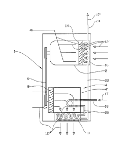
Fig. 1 shows a principle sketch of a breathing air unit according to the
invention;
and
Fig. 2 shows a symbol diagram for the breathing air unit in fig. 1.
In the drawings, reference numeral 1 denotes a breathing air unit comprising
an elec-
tric motor 2 and a compressor 4. The motor 2 drives the compressor 4 via a V-
belt
transmission 6.
The compressor 4, which in this preferred embodiment is a scroll compressor
with a
compressor housing 4, is provided with a compressor fan 8. The compressor fan
8 is
arranged in a manner allowing it to cause a first flow of cooling air 12 to
flow through
the compressor 4 when the compressor 4 is operating. The compressor fan 8 also
causes the first flow of cooling air 12 to flow through a first heat exchanger
10.
Arrows 12 in the figures show flow directions. The first flow of cooling air
12 flowing
internally in the compressor housing and across the compressor 4 has only been
in-
significantly heated when flowing into the first heat exchanger 10.
The motor 2 is provided with a motor fan 14 drawing a second flow of cooling
air 12'
into the motor 2 via an upstream second heat exchanger 16, the motor fan 14
being
arranged in a manner allowing it to blow the second flow of cooling air 12'
across the
motor 2. The second heat exchanger 16 is connected in a sealing manner to the
motor
fan 14 in such a way that all of the second flow of air 12' flowing through
the motor
fan 14 also must flow through the second heat exchanger 16.
Uncompressed breathable air 17, which is comprised of pre-filtered, ambient
air, flows

CA 02782003 2016-10-25
4
into the compressor 4 via an air inlet 18. Compressed breathable air 17' flows
from
the compressor 4 via a compressor pipe 20 and onto the first heat exchanger
10, and
then onto the second heat exchanger 16 via an intermediate pipe 22. The
compressed
breathable air 17' flows from the second heat exchanger 16 via an outlet pipe
24 and
onto, respectively, a water separator 26, a pressure vessel 28 and onwards via
filters
(not shown) and valves (not shown) onto a user (not shown); se figure 2.
Thus, the breathing air 17' compressed in the compressor 4 becomes cooled by
means
of the compressor cooling air 12 in the first heat exchanger 10, and then by
the motor
cooling air 12' in the second heat exchanger 16.
By so doing, the compressed breathable air 17' is cooled to a comfortable user
tem-
perature before reaching the user (not shown), and without having to pass
through
long hose- or pipe connections capable of causing condensation and bacterial
prob-
lems.

Representative Drawing
A single figure which represents the drawing illustrating the invention.
Administrative Status

For a clearer understanding of the status of the application/patent presented on this page, the site Disclaimer , as well as the definitions for Patent , Administrative Status , Maintenance Fee  and Payment History  should be consulted.

Administrative Status

Title Date
Forecasted Issue Date 2017-08-01
(86) PCT Filing Date 2010-12-02
(87) PCT Publication Date 2011-06-16
(85) National Entry 2012-05-25
Examination Requested 2015-06-08
(45) Issued 2017-08-01

Abandonment History

There is no abandonment history.

Maintenance Fee

Last Payment of $263.14 was received on 2023-11-09


 Upcoming maintenance fee amounts

Description Date Amount
Next Payment if standard fee 2024-12-02 $347.00
Next Payment if small entity fee 2024-12-02 $125.00

Note : If the full payment has not been received on or before the date indicated, a further fee may be required which may be one of the following

  • the reinstatement fee;
  • the late payment fee; or
  • additional fee to reverse deemed expiry.

Patent fees are adjusted on the 1st of January every year. The amounts above are the current amounts if received by December 31 of the current year.
Please refer to the CIPO Patent Fees web page to see all current fee amounts.

Payment History

Fee Type Anniversary Year Due Date Amount Paid Paid Date
Registration of a document - section 124 $100.00 2012-05-25
Application Fee $400.00 2012-05-25
Maintenance Fee - Application - New Act 2 2012-12-03 $100.00 2012-05-25
Maintenance Fee - Application - New Act 3 2013-12-02 $100.00 2013-10-21
Maintenance Fee - Application - New Act 4 2014-12-02 $100.00 2014-10-07
Request for Examination $800.00 2015-06-08
Maintenance Fee - Application - New Act 5 2015-12-02 $200.00 2015-10-21
Maintenance Fee - Application - New Act 6 2016-12-02 $200.00 2016-10-05
Final Fee $300.00 2017-06-20
Maintenance Fee - Patent - New Act 7 2017-12-04 $200.00 2017-10-24
Maintenance Fee - Patent - New Act 8 2018-12-03 $200.00 2018-11-13
Maintenance Fee - Patent - New Act 9 2019-12-02 $200.00 2019-11-21
Maintenance Fee - Patent - New Act 10 2020-12-02 $250.00 2020-11-19
Maintenance Fee - Patent - New Act 11 2021-12-02 $255.00 2021-11-03
Maintenance Fee - Patent - New Act 12 2022-12-02 $254.49 2022-11-11
Maintenance Fee - Patent - New Act 13 2023-12-04 $263.14 2023-11-09
Owners on Record

Note: Records showing the ownership history in alphabetical order.

Current Owners on Record
E INNOVATION AS
Past Owners on Record
None
Past Owners that do not appear in the "Owners on Record" listing will appear in other documentation within the application.
Documents

To view selected files, please enter reCAPTCHA code :


To view images, click a link in the Document Description column. To download the documents, select one or more checkboxes in the first column and then click the "Download Selected in PDF format (Zip Archive)" or the "Download Selected as Single PDF" button.

List of published and non-published patent-specific documents on the CPD .

If you have any difficulty accessing content, you can call the Client Service Centre at 1-866-997-1936 or send them an e-mail at CIPO Client Service Centre.


Document
Description 
Date
(yyyy-mm-dd) 
Number of pages   Size of Image (KB) 
Abstract 2012-05-25 1 51
Claims 2012-05-25 1 14
Drawings 2012-05-25 2 22
Description 2012-05-25 4 149
Representative Drawing 2012-07-19 1 5
Cover Page 2012-08-06 1 31
Description 2016-10-25 4 149
Claims 2016-10-25 1 36
Drawings 2016-10-25 2 24
Final Fee 2017-06-20 2 64
Representative Drawing 2017-07-05 1 7
Cover Page 2017-07-05 1 33
PCT 2012-05-25 6 247
Assignment 2012-05-25 6 206
Examiner Requisition 2016-04-25 3 223
Amendment 2015-06-08 2 77
Amendment 2016-10-25 10 307