Note: Descriptions are shown in the official language in which they were submitted.
:A 02782123 2012 05 25
WO 2010/106434 PCT/1B2010/000615
1
MICROFLUIDIC DEVICE FOR ISOLATION OF CELLS
TECHNICAL FIELD
The present invention relates to a microfluidic system, an
apparatus for isolation of particles, a microfluidic device,
and a method for isolation of particles.
BACKGROUND ART
Known to the art is a device for isolation of particles of a
given type, which comprises a main chamber, in which an
operator, using a pipette, introduces a sample through a hole
of the main chamber, and a recovery chamber, from which the
operator, once again using a pipette, draws the particles of
the given type through a hole of the recovery chamber.
The documents Nos. US2003/0073110 and EP1179585 disclose
complex devices for the manipulation of samples, which
comprise a plurality of valves completely contained in the
devices themselves.
The document No. US2004/0209354 discloses only some aspects of
a system for the manipulation of particles, details of the
structure of the device and of its operation are not
specified.
Known devices have various problems of precision during the
steps of separation, introduction, and recovery. Furthermore,
the results are not always reproducible, at times
contamination of the sample occurs during the various steps,
and the intervention of operators with particular manual
skills is frequently necessary.
DISCLOSURE OF INVENTION-
The aim of the present invention is to provide a microfluidic
system, an apparatus for isolation of particles, a
microfluidic device, and a method for isolation of particles,
:A 02782123 2012 05 25
WO 2010/106434 PCT/1B2010/000615
2
which will enable the drawbacks of the current art to be
overcome, at least partially, and will at the same time be
easy and economically advantageous to produce.
According to the' present invention, a microfluidic system is
provided in accordance with what is specified in the ensuing
independent claims and, preferably, in any one of the claims
that depend directly or indirectly upon the independent
claims.
Unless otherwise explicitly specified, in the present text the
following terms have the meaning indicated hereinafter.
By "equivalent diameter" of a cross section is understood the
diameter of a circle having the same area as the cross
section.
By "cross section" of a channel or of a duct is understood the
section substantially perpendicular to the longitudinal
extension of the channel (or duct) i.e., to the direction of
advance of the fluid in the channel (or duct).
By "equivalent diameter" of a hole is understood the diameter
of a circle having the same area as the cross section of
smallest dimensions of the hole itself.
By "microfluidic system (or device)" is understood a system
(or device) comprising at least one microfluidic channel (or
duct).
By "microfluidic channel (or duct)" is understood a channel
(or duct) having a cross section with equivalent diameter of
less than 1 mm.
The dimensions of the channels or ducts can be measured in a
standard way using profilometers.
A 02782123 2012-05-25
WO 2010/106434 PCT/1B2010/000615
3
In the present text, by "particle" is understood a corpuscle
having its largest dimension of less than 500
gm
(advantageously less than 150 gm). Non-limiting examples of
particles are: cells, cellular detritus (in particular, cell
fragments), cellular aggregates (such as, for example, smalL
clusters of cells deriving from stem cells, such as
neurospheres or mammospheres), bacteria, lipospheres,
(polystyrene and/or magnetic) microspheres, and complex
nanospheres (for example, nanospheres of up to 100 nm) formed
by microspheres linked to cells. Advantageously, the particles
are cells.
According to some embodiments, the particles (advantageously
cells and/or cellular detritus) have a largest dimension of
less than 60 pm.
The dimensions of the particles can be measured in a standard
way using microscopes with graduated scale or normal
microscopes used with graduated-scale slides (on which the
particles are deposited).
In the present text, by "dimensions" of a particle is
understood the length, the width, and the thickness of the
particle.
The term "substantially selective" is used for identifying a
displacement (or other analogous terms indicating a movement
and/or a separation) of particles, in which the particles that
are displaced and/or separated are particles for the vast
majority of one or more given types. Advantageously, a
substantially selective displacement (or other analogous terms
indicating a movement and/or a separation) envisages
displacement of particles with at least 90% (advantageously
95%) of particles of the given type or types (percentage given
by the number of particles of the given type or types with
respect to the total number of particles).
A 02782123 2012-05-25
WO 2010/106434 PCT/1B2010/000615
4
BRIEF DESCRIPTION OF THE DRAWINGS
The invention is described hereinafter with reference to the
annexed drawings, which illustrate some non-limiting examples
of embodiments thereof and in which:
Figure 1 is a schematic illustration of a system built
in accordance with the present invention;
Figure 2 is a schematic illustration of an alternative
embodiment of a system built in accordance with the present
invention;
Figure 3 is a schematic lateral view of the system of
Figure 1;
Figure 4 is an exploded perspective view of a device
built in accordance with the present invention;
Figure 5 is a top plan view of a component of the device
of Figure 4;
Figure 6 is a plan view from beneath of the component of
Figure 5;
Figure 7 is a perspective view of components of the
device of Figure 4;
Figure 8 is an exploded perspective view of a component
of the device of Figure 4;
Figure 9 is a top plan view of the component of Figure
8;
Figure 10 is a partial perspective view with items
removed for reasons of clarity of an apparatus built in
accordance with the present invention;
Figure 11 is a partial perspective view with items
removed for reasons of clarity of the apparatus of Figure
in a different operating position;
Figure 12 is a perspective view from beneath of a detail
of the apparatus of Figures 10 and 11;
Figure 13 is a top plan view of a part of the apparatus
of Figures 10 and 11, with items removed for reasons of
clarity;
Figures 14 and 15 illustrate in partial cross section a
:A 02782123 2012 05 25
WO 2010/106434 PCT/1B2010/000615
detail of the systems of Figures 1 to 3 in two different
operating positions;
Figure 16 illustrates in partial cross section a detail
of the systems of Figures 1 to 3;
Figure 17 is a perspective view of a part of the detail
illustrated in Figures 14 and 15;
Figure 18 is an exploded perspective view of the detail
of Figure 17;
Figures 19 and 20 illustrate a detail of the device of
Figure 4 in various operating steps;
Figure 21 is a top plan view of a device of Figure 4;
Figure 22 illustrates photographs of tests conducted
using the system of Figure 1;
Figure 23 illustrates at an enlarged scale an embodiment
of a detail of Figures 1 and 2;
Figure 24 is a perspective view of a variant of the part
illustrated in Figure 17;
Figure 25 is an exploded perspective view of the variant
of Figure 24;
Figure 26 is a lateral cross-sectional view of the
variant of Figure 24;
- Figures 27 and 28 illustrate a detail of the device of
Figure 31 in various operating steps;
- Figure 29 is an exploded perspective view of a component of
the device of Figure 31;
- Figure 30 is a top plan view of the component of Figure 29;
- Figure 31 is a top plan view of a device built in accordance
with the present invention;
- Figure 32 is a plan view from beneath of a variant of the
component of Figure 6 and, in particular, a component of the
device of Figure 31; and
- Figure 33 illustrates at an enlarged scale a detail of
Figure 32.
BEST MODE FOR CARRYING OUT THE INVENTION
Microfluidic system
A 02782123 2012-05-25
WO 2010/106434 PCT/1B2010/000615
6
Provided according to a first aspect of the present invention
is a microfluidic system 1 for the substantial isolation of
particles Cl (schematically illustrated in Figure 20) of at
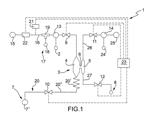
least one given type from a sample. The system 1 (Figure 1)
comprises: an inlet 2, through which, in use, the .ample is '
introduced into the system 1; a separation unit 3, which is
designed to separate in a substantially selective way at least
a part of the particles Cl of the given type from further
particles C2 of the sample (schematically illustrated in
Figure 20); and an outlet 8, which is connected to the
separation unit 3 and, in particular, through which, in use,
at least part of the particles Cl of the given type separated
in a substantially selective way exit from the system 1. The
separation unit 3 is connected to the inlet 2.
According to some embodiments, the system 1 comprises: a valve
9, set between the inlet 2 and the separation unit 3 (in
particular, between the inlet 2 and the main chamber 4); and a
valve 12, set between the outlet 8 and the separation unit 3.
In particular, the system 1 comprises a valve set between the
separation unit 3 and each opening of the system 1 towards the
outside.
According to some embodiments, the separation unit 3 comprises
a main chamber 4 and a recovery chamber 5 and is designed to
transfer at least part of the particles Cl of the given type
from the main chamber 4 to the recovery chamber 5 in a
substantially selective way with respect to the further
particles C2 of the sample.
The separation unit 3 further comprises a channel 5, which
connects (i.e., enables passage of fluid between) the chambers
4 and 5 and has dimensions (in particular, width and length)
much smaller than those of both of the chambers 4 and 5
themselves.
A 02782123 2012-05-25
WO 2010/106434 PCT/1B2010/000615
7
The system 1 is equipped with: an outlet 7, connected to the
main chamber 4 to enable the sample to enter freely within the
main chamber 4, thus functioning as breather; and the outlet
8, which is connected to the recovery chamber 5 and through
which, in use, at least part of the particles Cl Of the given
type collected in the recovery chamber 5 exit from the system
1.
The system 1 further comprises: the valve 9, set upstream of
the main chamber 4; a valve 10, set between the main chamber 4
and the outlet 7; a valve 11, connected to the recovery
chamber 5; and the valve 12, set between the recovery chamber
and the outlet 8. In particular, the valve 11 is set between
the recovery chamber 5 and a source of a carrier liquid.
More precisely, the recovery chamber 5 is set between the main
chamber 4 on one side and the valves 11 and 12 on the other
side; the main chamber 4 is set between the recovery chamber 5
on one side and the valves 9 and 10 on the other side.
The valves 9 and 10 are designed to regulate inflow of the
sample to the main chamber 4.
The valves 11 and 12 are designed to regulate inflow of a
carrier liquid to the recovery chamber 5 and outflow of the
carrier liquid together with the particles Cl of the given
type from the recovery chamber 5 through the outlet 8.
If, in use, the valves 9 and 12 are closed and the valves 11
and 10 are opened, a flushing of the main chamber 4 is carried
out; in other words, the further particles C2 of the sample
are discharged (i.e., made to flow away) from the main chamber
4.
According to specific embodiments, the carrier liquid is a
buffer solution, in particular phosphate-buffered saline
A 02782123 2012-05-25
WO 2010/106434 PCT/1B2010/000615
8
(PBS).
According to the embodiment illustrated in Figure 1, the
system 1 comprises: a reservoir 13, which is set between the
inlet 2 and the valve 9 and is designed to collect the sample
introduced through the inlet 1 itself; and a reservoir 14 for
containing the carrier liquid, which is designed to fill the
recovery chamber 5. In other words, the reservoir 14 functions
as source of the carrier liquid. The system 1 further
comprises a reservoir 7', which is set at the outlet 7 and is
designed to collect the fluids coming from the main chamber 4.
The valve 9 is set between the inlet 2 and the main chamber 4,
in particular between the reservoir 13 and the main chamber 4,
and is designed to connect or isolate the inlet 2 and the main
chamber 4 with respect to one another.
Advantageously, the system 1 further comprises a pressure
source 15 for imposing a pressure difference between the
reservoir 13 and the main chamber 5 in a direction of supply
of the given pressure. In particular, the pressure source 15
is designed to impose a pressure from the reservoir 13 towards
the main chamber 5 in a direction of supply of the given
pressure. According to some embodiments, the reservoir 13 is
set between the pressure source 15 and the valve 9.
In particular, the reservoir 13 is set between the pressure
source 15 and the main chamber 4.
According to specific embodiments, the system 1 comprises a
duct 16, which connects. (i.e., enables passage of fluid
between) the pressure source 15 and the main chamber 4 and
along which the reservoir 13 and the valve 9 are set. The duct
16 has a cross section of equivalent diameter of less than or
equal to 2 mm; advantageously, the duct 16 has a cross section
of equivalent diameter greater than or equal to 50 m. The
A 02782123 2012-05-25
WO 2010/106434 PCT/1B2010/000615
9
duct 16 comprises at least one stretch, which has a cross
section with equivalent diameter of less than or equal to
0.9 mm.
The system 1 further compi.ises a vibration device 17, which is
designed to cause variation in an oscillating way of the
pressure exerted on the sample at least in an area from the
inlet 2 to the main chamber 4 and is set between the pressure
source 15 and the reservoir 13. In this way, the particles Cl
and C2 of the sample present in the reservoir 13 and/or in the
duct 16 and/or in the main chamber 4 are made to vibrate;
inflow of the particles Cl and C2 of the sample from the
reservoir 13 to the main chamber 4 is improved. The particles
Cl and C2 have a smaller tendency to cluster or adhere to the
walls of the reservoir 13 and/or of the duct 16 and/or of the
main chamber 4. The homogeneity of the distribution of the
particles Cl and C2 within the main chamber 4 is improved.
Advantageously, the vibration device 17 comprises an
oscillating diaphragm 18, connected, in particular by means of
a T-joint 19, to the duct 16. According to specific
embodiments, the oscillating diaphragm is a micropump
(Thinxxs MDP2205) with inlet and outlet short-circuited.
According to some embodiments (not illustrated in Figure 1),
the inlet 2 is set along the duct 16, between the pressure
source 15 (in particular, the joint 19) and the reservoir 13.
According to some embodiments, the system 1 comprises a duct
20, which is set between the main chamber 4 and the outlet 7
and has at least one stretch 20' having a cross section
smaller than the cross section of the duct 16. In particular,
the cross section of the stretch 20' is smaller by at least
100 gm than the cross section of the duct 16. Advantageously,
the stretch 20' is set immediately downstream (i.e., without
interposition of further stretches or elements) of the main
A 02782123 2012-05-25
WO 2010/106434 PCT/1B2010/000615
chamber 4.
The stretch 20' has a width of less than 150 gm, a depth of
less than 110 gm, and a length greater than 2 mm.
Advantageously, the stretch 20' has a width greater than
100 m, a depth greater than 30 gm, and, in particular, a
length of less than 6 mm.
According to some embodiments, the duct 20 comprises a stretch
20", which is set between the stretch 20' and the outlet 7
and has a cross section of equivalent diameter greater than
that of the stretch 20' (in particular, substantially equal to
that of the duct 16).
In general, according to different embodiments, the system 1
comprises: a sensor for detecting directly or indirectly when
the sample starts to enter the duct 20; a blocking device for
blocking inflow of the sample towards the main chamber; and a
control assembly connected to the sensor and to the blocking
device for actuating the blocking device according to what is
detected by the sensor (in particular, when the sample starts
to enter the duct 20).
According to some specific embodiments, the system 1
comprises: a pressure sensor 21 for detecting pressure
variations along the duct 16 and/or at the main chamber 4; and
a blocking device 22 for blocking inflow of the sample towards
the main chamber 4. The system 1 further comprises a control
assembly 23 connected to the pressure sensor 21 and to the
blocking device 22 for actuating the blocking device 22 as a
function of the variation of pressure detected. In particular,
in use, the control assembly 23 actuates the blocking device
22 when the pressure sensor 21 detects a pressure greater than
a given threshold pressure.
According to further specific embodiments, the system 1
A 02782123 2012-05-25
WO 2010/106434 PCT/1B2010/000615
11
comprises, in addition or as an alternative to the pressure
sensor 21, one or more from among the following elements: an
optical sensor, set at the entrance of the stretch 20'; a
detector of electrical conductivity, which is set at the
'entrance of the stretch 20' for detecting variations, of
conductivity due to the start of the passage of the sample; a
detector of electrical permittivity, which is set at the
entrance of the stretch 20' for detecting variations of
permittivity due to the start of the passage of the sample; a
detector of thermal resistance, which is set at the entrance
of the stretch 20' for detecting variations of thermal
resistance due to the start of the passage of the sample; and
a detector of thermal capacity, which is set at the entrance
of the stretch 20' for detecting variations of thermal
capacity due to the start of the passage of the sample. In all
these cases, the control assembly 23 is connected to the
detector/detectors and is designed to actuate the blocking
device 20 as a function of the variations detected by the
detector/detectors.
According to some embodiments, the optical sensor is an
integrated photodiode or else an external video camera
(possibly with a system for image enlargement).
With particular reference to Figure 23, the blocking device 22
comprises a relief valve 22' and is, advantageously, set
between the pressure source 15 and the reservoir 13; when the
blocking device 22 is operated, the relief valve 22' is
opened, and the jet of air coming from the pressure source 15
is released towards the outside, and the pressure along the
duct 16 drops. The relief valve 22' is hydraulically connected
to the duct 16 by means of a T-joint 22".
In particular, the blocking device 22 is set between the joint
19 and the pressure source 15, specifically upstream of the
pressure sensor 21 with respect to the direction of supply of
A 02782123 2012-05-25
WO 2010/106434 PCT/1B2010/000615
12
the pressure to the main chamber 4.
From what has been set forth above, it may be inferred that
introduction of the sample into the separation unit 3 is
improved, so reducing the risk of a significant part of the
sample passing beyond the separation unit 3 itself.
According to alternative embodiments, the blocking device 22
is not present, the blocking function being performed by the
valve 9, which is connected to the control assembly 23. In
other words, the control assembly 23, in use, closes the valve
9 when the pressure sensor 21 detects a pressure higher than
the given threshold pressure.
Advantageously, the control assembly 23 is connected to the
valves 9, 10, 11, and 12.
The connection between the control assembly and other elements
(devices, valve units, etc.) can be provided via traditional
electrical connections (conductor cables) or else via
electromagnetic waves (for example, by means of radio waves,
microwaves, etc.).
According to some embodiments, the system 1 comprises an inlet
24. The reservoir 14 is set between the inlet 24 and the valve
11 and is designed to collect the carrier liquid introduced
through the inlet 24.
The valve 11 is set between the inlet 24 and the recovery
chamber 5 and is designed to connect or isolate the inlet 24
and the recovery chamber 5 with respect to one another. In
particular, the valve 11 is set between the reservoir 14 and
the recovery chamber 5 and is designed to connect or isolate
the reservoir 14 and the recovery chamber 5 with respect to
one another.
A 02782123 2012-05-25
WO 2010/106434 PCT/1B2010/000615
13
According to some embodiments, the system 1 comprises a
pressure source 25 for imposing a pressure difference between
the reservoir 14 and the recovery chamber 5. In particular,
the pressure source 25 imposes a pressure from the reservoir
14 towards the recovery chamber 5.
Advantageously, the reservoir 14 is set between the pressure
source 25 and the valve 11. In particular, the system 1
comprises a duct 26, which connects (i.e., enables passage of
fluid between) the pressure source 25 and the recovery chamber
and along which the reservoir 14 and the valve 13 are set.
According to some embodiments, the inlet 24 is set along the
duct 26, in particular between the pressure source 25 and the
reservoir 14.
With particular reference to Figure 3, the system 1 comprises
a vibration device 17a, which is similar to the vibration
device 17 and is designed to cause a variation in an
oscillating way of the pressure at least in an area of the
recovery chamber 5. In this way, the particles Cl of the given
type present within the recovery chamber 5 are made to
vibrate, and the outflow of the particles Cl of the given type
itself from the recovery chamber 5 towards the outlet is
improved. The particles Cl have a reduced tendency to cluster
or adhere to the walls of the recovery chamber 5 and/or of a
duct 27 that connects (i.e., enables passage of fluid between)
the recovery chamber 5 to the outlet 8. The valve 12 is set
between the recovery chamber 5 and the outlet 8.
Advantageously, the vibration device 17a comprises a diaphragm
pump 18a connected, in particular by means of a T-joint 19a,
to the duct 26.
According to embodiments (not illustrated), the system for
filling of the chamber 5 is similar to that for the chamber 4.
A 02782123 2012-05-25
WO 2010/106434 PCT/1B2010/000615
14
Consequently, in said cases, a blocking device (not
illustrated) is set between the pressure source 25 and the
reservoir 14; moreover, one or more sensors and/or detectors
(not illustrated) analogous to the ones described above with
reference to the main chamber 4 are arranged at the entrance
of the duct 27 or in other appropriate positions.
According to embodiments (not illustrated), the system 1
comprises a detector (in particular, an optical or
impedentiometric or ultrasound detector), which is set at the
outlet 8, is connected to the control assembly 23, and is
designed to detect a liquid that exits from the outlet 8. The
control assembly 23 is designed to regulate the opening of the
valve 11 and/or 12 as a function of what is detected by the
optical sensor. In particular, in use, when the optical sensor
detects at least one drop of carrier liquid (in which at least
part of the particles Cl of the given type is present) the
control assembly 23 actuates a relief valve, which brings the
actuation pressure to zero, thus blocking the flow of the
liquid.
In addition or as an alternative, when the optical sensor
detects at least one drop of carrier liquid (in which at least
part of the particles Cl of the given type is present) the
control assembly 23 closes the valve 12 and/or the valve 11.
In this way, it is possible to obtain the particles Cl in a
very small volume of liquid. This facilitates the subsequent
steps of analysis.
Figure 2 illustrates an embodiment of the system 1 that
differs from the system 1 of Figure 1 for the position of the
duct 26 with respect to the recovery chamber 5 and in that it
comprises a duct 28, which connects the recovery chamber 5 to
the outlet 7 (or to a further outlet, not illustrated) and
along which a valve 29 is set, connected to the control
A 02782123 2012-05-25
WO 2010/106434 PCT/1B2010/000615
assembly 23. The duct 26 connects up to the recovery chamber 5
between the ducts 27 and 28. In particular, the duct 26
connects up to the recovery chamber 5 substantially in front
of the channel 6.
With particular reference to Figures 14 and 15, according to
some embodiments, at least one from among the valves 9, 10, 11
and 12 (in particular, each valve 9, 10, 11 and 12) has a
particular structure described below with reference to a
particular valve V (in other words, one or more of the valves
9, 10, 11 and 12 has the structure of the valve V described
below).
According to one aspect of the present invention, a valve V is
provided.
The valve V is equipped with a closing element 30, which
comprises (in particular, is made of) a substantially elastic
material, and is designed to pass between a blocking position
(illustrated in Figure 14), in which the closing element
30 separates two stretches 31 and 32 of a respective duct, and
an opening position (illustrated in Figure 15), in which the
closing element 30 is set in such a way that the passage of
fluid between the stretches 31 and 32 is allowed.
The valve V comprises a diaphragm 33, which is set between the
two stretches 31 and 32. When the closing element 30 is set in
the blocking position, the closing element 30 itself is in
contact with the diaphragm 33 so as to separate the stretches
31 and 32. When the closing element 30 is set in the opening
position, the closing element 30 itself is set at a distance
from the diaphragm 33 so as to enable the passage of fluid
between the stretches 31 and 32.
The valve V further comprises a respective mechanical pressure
element 34, which pushes the closing element 30 towards the
A 02782123 2012-05-25
WO 2010/106434 PCT/1B2010/000615
16
stretches 31 and 32 (in particular, towards the diaphragm 33)
so as to keep the closing element 30 itself in the blocking
position. Advantageously, the mechanical pressure element 34
comprises (in particular, is) a spring, which is compressed
when _the closing element 34 passe 'S from the blocking position
to the opening position and extends when the closing element
34 passes from the opening position to the blocking position.
The valve V comprises a fluid-dynamic actuator 35, which in
turn comprises an actuator nozzle 36 equipped with a hollow
element 37, which houses the mechanical pressure element 34.
The hollow element 37 has an internal channel 38 and an open
end (in particular, provided with an actuator hole 39) set in
contact with the closing element 34.
The fluid-dynamic actuator 35 comprises a sealing element 40,
which is designed to slide in a fluid-tight way along the
internal channel 38 and is set in a position corresponding to
the actuator hole 39 in contact with the mechanical pressure
element.
The fluid-dynamic actuator 35 further comprises a suction unit
41, which, in turn, comprises a duct 42 that connects the
actuator nozzle 36 to a suction source 43 (illustrated in
Figure 3).
In use, when the suction unit 41 is operated, the sealing
element 30 is sucked back and pushes the sealing element 40,
which slides within the internal channel 38 so as to compress
the mechanical pressure element 34. Said negative pressure
moves the closing element 30 away from the diaphragm 33 in
such a way that the closing element 30 reaches the opening
position. When the suction unit is deactivated, the mechanical
pressure element 34 pushes the sealing element 40 towards the
outside through the actuator hole 39. The sealing element 40
in turn pushes the closing element 30 against the diaphragm 33
:A 02782123 2012 05 25
WO 2010/106434 PCT/1B2010/000615
17
in such a way that the closing element 30 itself reaches the
blocking position.
The closing element 30 (also illustrated in Figure 7) has a
membrane pbrtion 44 nd a projection 45 that extends along a
perimetral edge of the membrane portion 44. In other words,
the closing element 30 has a larger thickness at the
perimetral edge. This enables improvement of the mechanical
resistance of the membrane and fluid tightness between the
closing element 30 and the actuator nozzle 36 (in particular,
the hollow element 37). The projection 45 has an annular
shape.
According to specific embodiments, the membrane portion 44 has
a substantially cylindrical shape; in this case, the
projection 45 has the shape of a circular ring.
According to some embodiments, the closing element 30 is made
up of a single elastomeric material (i.e., an elastomer) or
else by a combination (for example, a mixture) of a number of
elastomeric materials that are different from one another.
Advantageously, the elastomer comprises (in particular,
consists of) a silicone, in particular a silicone rubber.
According to some embodiments, the silicone has the following
formula:
[R2SiO]n
where n is an integer greater than 4, each R is chosen,
independently of the others, in the group consisting of:
methyl, ethyl, propyl.
According to some embodiments, the elastomer comprises (i.e.,
is constituted by) just one silicone or, alternatively, a
number of silicones that are different from one another.
A 02782123 2012-05-25
WO 2010/106434 PCT/1B2010/000615
18
According to some embodiments, set underneath the actuator
nozzle 36 is a mechanical pressure element 46 (in particular,
a spring) for pushing the actuator nozzle 36 itself against
the closing element 30.
According to a variant, the fluid-dynamic actuator 35 has the
structure illustrated in Figures 24 to 26, in which the
sealing element 40 comprises two components 40' and 40",
which can be dismantled.
It should be emphasized that the particular structure of the
valve V has significant advantages over the prior art.
A first advantage consists in the lower risk of gas
contamination (in particular, air) of the sample. In this
regard, it should be noted that usually the closing element
30 is partially permeable to gas and that in the solution
proposed it is not necessary to supply a jet of air to keep
the closing element 30 in the blocking position (by supplying
the jet of air, part of the jet of air would enter the duct).
A second advantage consists in the reduction of the head
losses when the suction source is functioning (the parts are
fitted together so as to present a high fluid tightness).
In the embodiment of Figure 3, the valves 9 and 11 are
illustrated schematically and substantially have the same
structure as the valve V described above. In this case,
advantageously, the valves 9 and 11 are each connected to a
respective suction source 43.
According to some embodiments (not illustrated), the system 1
does not comprise the pressure sources 15 and 25. In this
case, the valves 9 and/or 11, instead of being single valves
comprise a plurality of valves arranged in succession along
the duct 16 and/or 26. In use, the valves arranged in
A 02782123 2012-05-25
WO 2010/106434 PCT/1B2010/000615
19
succession are opened and closed in sequence to supply the
sample and/or the carrier liquid to the separation unit 3. In
this way, the valves arranged in succession work in a way
similar to a peristaltic pump.
It should be noted that to work as a peristaltic pump at least
three valves arranged in succession are normally necessary.
According to some embodiments, however, the valves 9 and/or 11
each comprise (in particular, consist of) two valves arranged
in succession. In these cases, said valves are operated in
combination with the valves 10 and/or 12 to work as a
peristaltic pump.
These embodiments present some advantages: they do not require
integration of cumbersome pressure sources; and they enable in
a very precise way regulation of the amount of fluid that is
fed to the separation unit 3.
In accordance with the embodiment illustrated in Figure 3, the
system 1 comprises a dielectrophoresis system. The separation
unit 3 comprises at least one part of the dielectrophoresis
system. According to some embodiments, the separation unit 3
comprises the dielectrophoresis system (in its entirety).
In particular, the system 1 (specifically the
dielectrophoresis system) comprises an optical sensor 47. The
control assembly 23 is connected to the optical sensor 47 and
to the separation unit 3. Advantageously, the optical sensor
46 comprises a video camera 48. In use, the control assembly
23 actuates different active components of the chambers 4 and
as a function of what is detected by the optical sensor 47.
According to some embodiments, the separation unit 3 further
comprises an operator interface 49 (human/machine interface).
Advantageously, the operator interface 49 comprises a personal
CA 02782123 2016-07-29
computer.
According to some embodiments, the dielectrophoresis system
and/or its operation are/is as described in at least one of the
patent applications Nos. W00069565, W02007010367, W02007049120,
the contents of which are integrally recalled herein for
completeness of description.
According to some embodiments, the system 1 (Figure 2)
comprises a cooling assembly 50, which is designed to cool at
least part of the separation unit 3, in particular the main
chamber 4 and the recovery chamber 5.
The cooling assembly 50, according to some embodiments, is a
Peltier assembly and comprises: a cooling plate 51 having an
active surface 52, designed to absorb the heat from the
separation unit 3; and a discharging surface 53 for yielding
heat. Advantageously, the active surface 52 has a smaller
extension than the discharging surface 53.
According to some embodiments, set between the active surface 52
and the separation unit 3 is a mat (in itself known) made of a
heat-conductive polymeric material.
The cooling assembly 50 further comprises a heat-transfer plate
54 connected to a conditioning circuit 55, which functions as
heat-exchanger device.
The circuit 55 comprises: two ducts 56; a radiator 57, which is set
between the two ducts 56; a plurality of fans 58 for cooling a
conditioning liquid whilst it flows within the radiator 57; and a
pump 59 to cause the conditioning liquid to flow along the ducts 56
and through the radiator 57.
According to the embodiment illustrated in Figure 3, the
A 02782123 2012-05-25
WO 2010/106434 PCT/1B2010/000615
21
system 1 comprises at least one (in the case in point, four)
mechanical pressure element 60 (in particular, a spring) for
pushing the cooling assembly 50 towards the main chamber 4 and
the recovery chamber 5.
With particular reference to Figures 16, 18, 13, and 3, the
system 1 further comprises two pressure-supply nozzles 61 and
61a arranged between two stretches of the duct 16 and of the
duct 26, respectively.
The pressure-supply nozzle 61 comprises a hollow body 62,
which is connected to a pressure device 64, and has a
pressure-supply hole 63 set at an opposite end with respect to
the pressure device 64.
The pressure device 64 comprises a pressure unit 65, which, in
turn, comprises the pressure source 15 and a duct (in
particular, a first stretch of the duct 16), which connects
the pressure source 15 to the pressure-supply nozzle 61.
Set between the pressure-supply hole 63 and a second stretch
of the duct 16 is a seal ring 66 (illustrated in Figures 7,
16) comprising (in particular, consisting of) a substantially
elastic material.
Advantageously, the substantially elastic material is defined
as described above with reference to the closing element 30.
According to some embodiments, the seal ring 66 is
substantially circular and has: a substantially central hole
67; an internal portion that delimits the hole 67; and a
peripheral portion having a larger thickness than an internal
portion.
According to some embodiments, the system 1 further comprises
at least one mechanical pressure element 68 (in particular, a
A 02782123 2012-05-25
WO 2010/106434 PCT/1B2010/000615
22
spring), which is set so as to push the pressure-supply nozzle
63 towards (in particular, against) the seal ring 66. In this
way, a smaller dispersion of the pressure (i.e., a better
seal) is obtained between the pressure-supply nozzle 63, the
seal ring 66 .and the second stretch of the duct i6. The
mechanical pressure element 68 has the important function of
compensating for any possible lack of planarity of the device
and regulating the forces of contact applied.
According to advantageous embodiments, the pressure-supply
nozzle 61a has the same structure as the pressure-supply
nozzle 61, is connected to the pressure device 64 and is
pushed towards a respective seal ring 66a by a corresponding
mechanical pressure element 68a.
The system 1 further comprises a seat 69 (partially
illustrated in Figure 13), which is designed to house a
removable collector (for example, a test tube), of a type in
itself known and not illustrated, and is set at the outlet 8.
Set between the duct 27 and the seat 69 is a seal ring 70,
which is designed to guarantee a smaller dispersion (i.e., a
better seal) between the duct 27 and the seat 69. The seal
ring 70 comprises (in particular, consists of) a substantially
elastic material.
Advantageously, the substantially elastic material is defined
as described above with reference to the closing element 30.
According to some embodiments, the
seal ring 70 is
substantially circular and has: a substantially central hole
71; an internal portion that delimits the hole 71; and a
peripheral portion having a larger thickness than an internal
portion.
According to some embodiments, the system 1 comprises two
A 02782123 2012-05-25
WO 2010/106434 PCT/1B2010/000615
23
separable portions: a substantially fixed apparatus 72 (an
embodiment of the apparatus 72 is partially illustrated in
Figures 10 and 11) and a device 73 (an embodiment of the
device 73 is illustrated in top plan view in Figure 21 and in
exploded view in Figure 4).
According to a particular aspect of the present invention, a
microfluidic system is provided for isolation of particles Cl
of at least one given type from a sample, the system 1
comprising: a first inlet 2, through which, in use, the sample
is introduced into the system 1; a separation unit 3, which
comprises a main chamber 4 and a recovery chamber 5 and is
designed to transfer at least part of the particles Cl of the
given type from the main chamber 4 to the recovery chamber 5
in a substantially selective way with respect to further
particles C2 of the sample; a first outlet 7, connected to the
main chamber 4; and a second outlet 8, which is connected to
the recovery chamber 5, through which, in use, at least part
of the particles Cl of the given type collected in the
recovery chamber 5 exit from the system 1; the system 1 being
characterized in that it comprises: a first valve 9, set
upstream of the main chamber 4; a second valve 10, set between
the main chamber 4 and the first outlet 7; a third valve 11,
set upstream of the recovery chamber 5; and a fourth valve 12,
set between the recovery chamber 5 and the second outlet 8.
According to some embodiments, the system comprises one or
more of the characteristics described above in accordance with
the first and second aspects of the present invention.
In use, the system 1 (in accordance with one or more of the
aspects of the invention referred to above) is used according
to the method described hereinafter.
Method
Provided according to a third aspect of the present invention
A 02782123 2012-05-25
WO 2010/106434 PCT/1B2010/000615
24
is a method for isolation of particles Cl of at least one
given type from a sample by means of a microfluidic system.
The microfluidic system is the system 1 or a microfluidic
system similar to the system 1. Advantageously, the
microfluidic system is the 'system 1 as described above in
accordance with one of the preceding aspects of the present
invention. In any case, for reasons of simplicity in the
ensuing description of the method the microfluidic system and
its parts will be identified with the reference numbers used
above for identifying the system 1 and similar or identical
parts, respectively.
The method comprises: a step of introduction of the sample
into a system 1 through an inlet 2 of the system 1; a
separation step, during which at least part of the particles
Cl of the given type are separated from further particles C2
within a separation unit 3 of the system 1; a first supply
step, which at least partially precedes the separation step
and during which at least part of the sample is fed to the
separation unit 3 (the first supply step is schematically
illustrated in Figures 19e-19i); and a recovery step, which is
at least partially subsequent to the separation step and
during which at least part of the particles Cl of the given
type separated in a substantially selective way flow away from
the separation unit 3 through an outlet 8 of the system 1 (the
recovery step is schematically illustrated in Figures 20c and
20d).'
According to some embodiments, the system 1 comprises: a valve
9 set between the inlet 2 and the separation unit 3; and a
valve 12 set between the outlet 8 and the separation unit 3.
During the separation step, the valves 9 and 12 are kept
closed.
In particular, the system 1 comprises a valve set between each
opening (for example, inlets and/or outlets) of the system 1
A 02782123 2012-05-25
WO 2010/106434 PCT/1B2010/000615
towards the outside and the separation unit 3. During the
separation step, each of these valves is kept closed.
According to some embodiments, the recovery step is completely
subsequent to the separation step.
According to some embodiments, the separation step is
completely subsequent to the first supply step.
According to some embodiments, during the separation step, the
particles Cl of the given type are transferred from a main
chamber 4 to a recovery chamber 5 of the separation unit 3 in
a substantially selective way with respect to further
particles C2 of the sample (the end of the separation step is
illustrated in Figure 20a).
According to some embodiments, during the separation step,
using a system as described in Figure 2, the particles Cl of a
number of given types are transferred from a main chamber 4 to
a particular area of the recovery chamber 5 isolated via fluid
resistance from the rest of the recovery chamber.
An outlet 7 and an outlet 8 of the system 1 are connected to
the main chamber 4 and to the recovery chamber 5,
respectively.
Advantageously, the system 1 comprises: the valve 9, which is
set upstream of the main chamber 4; a valve 10, set downstream
of the main chamber 4; a valve 11, set upstream of the
recovery chamber 5; the valve 12, set downstream of the
recovery chamber 5. During the separation step, the valves 9,
10, 11, 12 are closed, in particular so as to isolate the main
chamber 4 and the recovery chamber 5 with respect to the
outside.
The method further comprises: the first supply step, which at
A 02782123 2012-05-25
WO 2010/106434 PCT/1B2010/000615
26
least partially precedes the separation step and during which
at least part of the sample is fed into the main chamber 4
(the first supply step is schematically illustrated in Figures
19e-19i); and a second supply step, which at least partially
precedes the separation step and during which the carrier.
liquid is fed to the recovery chamber 5 (the second supply
step is illustrated in Figures 19a-19d).
The method further comprises the recovery step, during which
the carrier liquid, together with at least part of the
particles Cl of the given type, flow away from the recovery
chamber 5 through the outlet 8 (the recovery step is
schematically illustrated in Figures 20c and 20d).
According to some embodiments, during the step of introduction
at least part of the sample is introduced into a reservoir 13
of the system 1.
Advantageously, the separation step occurs by
dielectrophoresis. At least during the separation step, the
separation unit 3 is cooled.
According to some embodiments, at least one or both of the
first and the second supply steps are completely prior to the
separation step.
According to some embodiments, the second supply step at least
partially precedes the first supply step. Advantageously, the
second supply step is completely prior to the first supply
step.
According to some embodiments, a first pressure is set to
supply the sample to the main chamber 4.
In particular, the first pressure pushes the sample from the
reservoir 13 towards the main chamber 4.
A 02782123 2012-05-25
WO 2010/106434 PCT/1B2010/000615
27
According to some embodiments, the first pressure is exerted
at least prior to and during the first supply step.
Advantageously, during the recovery step, at least part of the
particles Cl of the given type are subjected to vibration; in
particular, they are subjected to a pressure that varies in an
oscillating way (the frequency of vibration is between 2 Hz
and 80 Hz, advantageously from 5 Hz to 40 Hz).
Advantageously, during the first supply step a valve 9 of the
system 1, said valve 9 being set upstream of the main chamber
4, and a valve 10 of the system 1, said valve 10 being set
between the main chamber 4 and the outlet 7, are open. In
particular, during the first supply step, the sample passes
through the valve 9.
According to some embodiments, during the first supply step,
the sample is subjected to vibration; in particular, it is
subjected to a pressure that varies in an oscillating way (the
frequency of vibration is between 2 Hz and 80 Hz,
advantageously from 5 Hz to 40 Hz).
According to particular embodiments, the system 1 comprises: a
duct 16 for connecting the inlet 2 to the main chamber 4; and
a duct 20, which is set between the main chamber 4 and the
outlet 7 and has a cross section smaller, in particular by at
least 100 gm, than the cross section of the duct 16; during
the first supply step, the pressure of the sample being
detected; supply of the sample being blocked according to the
pressure detected, in particular when a pressure higher than a
given value is detected.
According to further embodiments, in addition or as an
alternative to the detection of pressure one or more of the
following detections is made: optical detection of the passage
of the sample between the chamber 4 and the duct 20; detection
of the variation of the electrical conductivity in an area of
A 02782123 2012-05-25
WO 2010/106434 PCT/1B2010/000615
28
connection between the chamber 4 and the duct 20 due to the
start of the passage of the sample; detection of the variation
of the electrical permittivity in an area of connection
between the chamber 4 and the duct 20 due to the start of the
passage of the sample; detection _of the variation of the
thermal resistance in an area of connection between the
chamber 4 and the duct 20 due to the start of the passage of
the sample; and detection of the variation of the thermal
capacity in an area of connection between the chamber 4 and
the duct 20 due to the start of the passage of the sample.
In all the above cases, inflow of the sample 40 is blocked
when it is found that the sample starts to enter the duct 20.
According to some embodiments, during the second supply step,
a valve 11 of the system 1, said valve 11 being set upstream
of the recovery chamber 5, and a valve 12, said valve 12 being
set between the recovery chamber 5 and the outlet 8, are open.
Advantageously, a second pressure is set to supply the carrier
liquid to the recovery chamber 5. In particular, the second
pressure pushes the carrier liquid from a reservoir 14 of the
system 1 towards the recovery chamber 5. During the second
supply step, the carrier liquid passes through the valve 11.
According to some embodiments, the second pressure is exerted
at least before and during the second supply step.
During the recovery step the valves 11 and 12 are open.
According to some embodiments, the method comprises a step of
discharge, which is at least partially subsequent to the
separation step and at least partially prior to the recovery
step and during which at least part of the further particles
C2 of the sample are made to flow away from the main chamber 4
through the outlet 7; the discharge step is schematically
A 02782123 2012-05-25
WO 2010/106434 PCT/1B2010/000615
29
illustrated in Figures 20b and 20c. Advantageously, the
discharge step is completely subsequent to the separation step
and/or completely prior to the recovery step.
During the discharge step, the valves 10 and 11 are open so as
to supply the carrier liquid to the main chamber 4.
Carrying-out of the discharge step enables reduction of the
risks of part of the further particles C2 that are recalled
from the main chamber 4 by the flow of the carrier liquid
through the recovery chamber 5 from passing, during the
recovery step, through the outlet 8.
In practice, according to some embodiments, the valves 11 and
12 are opened so as to fill the recovery chamber 5 with the
carrier liquid. At this point, the valves 9 and 10 are opened,
in such a way that the sample will fill the main chamber 4.
The valves 9, 10, 11 and 12 are, then, closed, and the
particles Cl of the given type are brought in a substantially
selective way from the main chamber 4 to the recovery chamber
5. At this point, the valves 11 and 10 are opened so as to
cause at least part of the further particles C2 to flow away
from the chamber 4.
According to some embodiments, the particles Cl of the given
type are arranged within the recovery chamber 5 in such a way
that, during the discharge step, they remain at least in part
inside the recovery chamber 5 itself. In particular, the
particles Cl of the given type are arranged laterally with
respect to (i.e., not in front of) a channel 6 for connection
between the main chamber 4 and the recovery chamber 5.
Specifically, the particles C2 are arranged between the
channel 6 and a duct 26 for connection to the outlet 8.
According to some embodiments, the system 1 comprises a valve
29 (Figures 2 and 27), which is set between the recovery
A 02782123 2012-05-25
WO 2010/106434 PCT/1B2010/000615
chamber and the outlet 7 (or a further outlet not
illustrated). The chamber 5 comprises: a first area 5' which
is hydraulically connected to the duct 27 (and hence to the
valve 12); a second area 5", hydraulically connected to the
duct 28 (and hence to the valve 29); and a further 'area, which
defines a terminal stretch of the duct 26 (and is hence
connected to the valve 11).
During the second filling step, the valves 12 and 11 are open
so as to fill the first area 5' of the recovery chamber 5,
which connects the valves 12 and 11; the valves 11 and 29 are
open for filling the second area 5" of the recovery chamber 5
that connects the valves 11 and 29.
According to specific embodiments, the valves 12, 11 and 29
are opened so as to fill the first area 5' (Figures 27b and
27c); at this point, the valve 12 is closed and the second
area 5" is filled (Figure 27d).
During the separation step, at least part of the particles Cl
of the given type and at least part of the particles C3 of at
least one second given type are transferred into the recovery
chamber 5 (Figures 28a and 28b) (in particular, into the
second area 5"). The recovery step comprises a first recovery
substep, during which at least pert of the particles Cl of the
given type is brought in a substantially selective way into
the first area 5' (Figure 28d) and, subsequently, at least
part of the particles Cl of the given type is made to flow
away from the first area 5' through the outlet 8 by supplying
to the recovery chamber 5 further carrier liquid (Figure 28e).
The recovery step comprises a second recovery substep, during
which at least part of the particles C3 is made to exit from
the recovery chamber 5 through the outlet 8 by supplying to
the recovery chamber 5 further carrier liquid.
A 02782123 2012-05-25
WO 2010/106434 PCT/1B2010/000615
31
Advantageously, during the second recovery substep, at least
part of the particles C3 is brought into the first area 5'
(Figures 28e and 28f) and, subsequently, at least part of the
particles C3 is made to flow away from the first area 5'
through the outlet 8 (Figure 28g).
According to some embodiments, the method comprises a flushing
step, during which further particles C2 present in the main
chamber 4 are removed from the channel 6. During the flushing
step, the valves 11 and 10 are opened (Figure 28c).
Advantageously, during the flushing step, the valve 29 is
closed and the particles Cl and C3 are arranged in the second
area 5". Advantageously, during the flushing step, the valve
12 is closed. Advantageously, during the flushing step, the
valve 9 is closed.
Advantageously, the flushing step is at least partially (in
particular, completely) subsequent to the recovery step and at
least partially (in particular, completely) prior to the
recovery step.
According to some embodiments, during the recovery step, the
first drop of carrier liquid that exits from the outlet 8 is
detected; when the first drop is detected, outflow from the
recovery chamber 5 is blocked.
According to some embodiments, a number of recovery steps
succeed one another, changing the containers arranged in the
proximity of the outlet 8 whenever at least one drop is
detected.
According to some embodiments, carbon dioxide is fed into the
system 1. In this way, the presence of oxygen inside the
system 1 is reduced or eliminated. The presence of oxygen
inside the system can lead to formation of bubbles during the
various steps of the method.
A 02782123 2012-05-25
WO 2010/106434 PCT/1B2010/000615
32
According to alternative embodiments, the carrier liquid
(and/or possibly the sample) is degassed by means of
ultrasound before introduction into the system 1 (or into the
separation unit 3).
Advantageously, the sample and the carrier liquid are used at
a temperature higher than 20 C, in particular higher than
25 C. Also this reduces the risk of formation of bubbles.
According to some embodiments, the method is applied using a
system 1 defined in accordance with the first aspect of the
present invention.
According to some embodiments, the system 1 comprises two
separable portions: a substantially fixed apparatus 72 (an
embodiment of the apparatus 72 is partially illustrated in
Figures 10 and 11) and a device 73 (an embodiment of the
device 73 is illustrated in top plan view in Figure 21 and in
exploded view in Figure 4). The device 73 is advantageously
disposable and designed to be connected to the apparatus 72.
According to some embodiments, only part of the sample is
brought into the main chamber 4. In practice, the sample is
subjected to a plurality of successive partial separations.
Microfluidic device
Provided according to a fourth aspect of the present invention
is the device 73 for isolation of particles Cl of at least one
given type from a sample. The device 73 comprises: the inlet
2, through which, in use, the sample is introduced into the
device 73; and the separation unit 3, which comprises a main
chamber 4 and a recovery chamber 5. The separation chamber 3
(in particular, the main chamber 4) is connected to the inlet
2. In particular, the separation unit 3 comprises part of the
dielectrophoresis system.
A 02782123 2012-05-25
WO 2010/106434 PCT/1B2010/000615
33
In use, when the device 73 is mounted within the apparatus 72,
the separation unit 3 is designed to transfer at least part of
the particles Cl of the given type from the main chamber 4 to
the recovery chamber 5 in a substantially selective way with
respect to fiirther particles C2 of the sample.
According to some embodiments, the device 73 comprises the
outlet 7 connected to the main chamber 4; the outlet 8 is
connected to the recovery chamber 5.
Through the outlet 8, in use, at least part of the particles
Cl of the given type collected in the recovery chamber 5 exit
from the device 73.
The outlet 7 is designed to enable the sample to enter freely
within the main chamber 4, thus functioning as breather.
The device 73 further comprises; a valve portion 74, which is
set upstream of the main chamber 4 (in particular, between the
main chamber 4 and the inlet 2); and a valve portion 75, which
is set between the main chamber 4 and the outlet 7.
The valve portion 74 is designed to form part of the valve 9.
The valve portion 75 is designed to form part of the valve 10.
The device also comprises: a valve portion 76, which is
connected to the recovery chamber 5; and a valve portion 77,
which is set between the recovery chamber 5 and the outlet 8.
In particular, the recovery chamber 5 is set between the main
chamber 4 on one side and the third and fourth valve portions
76, 77 on the other side; the main chamber 4 is set between
the recovery chamber 5 on one side and the first and second
valve portions 74 and 75 on the other side.
The valve portion 75 is designed to form part of the valve 11.
The valve portion 76 is designed to form part of the valve 12.
A 02782123 2012-05-25
WO 2010/106434 PCT/1B2010/000615
34
According to some embodiments, at least one of the valve
portions 74, 75, 76 and 77 comprises the closing element 30,
which is designed to pass between a blocking position, in
which the closing element 30 is set so as to separate two
stretches of a respective channel of the device 73, and an
opening position, in which the closing element 30 is set in
such a way that the two stretches are connected to one
another. Advantageously, each valve portion 74, 75, 76 and 77
comprises a respective closing element 30.
Advantageously, the closing element 30 is defined as described
above in relation to the system 1. In particular, the closing
element 30 has a membrane part, which comprises, in particular
is made of, a substantially elastic material.
According to some embodiments, at least one, in particular
each, of the valve portions 74, 75, 76 and 77, comprises the
diaphragm 33, which is set between the two stretches of the
duct of the device 73. In the blocking position the closing
element 30 is in contact with the diaphragm 33; in the opening
position the closing element 30 is set at a distance from the
diaphragm 33.
At least one, in particular each, of the valve portions 74,
75, 76 and 77 comprises at least one hole in a channel of the
device 73. In particular, each closing element 30 is set in a
point corresponding to two respective holes of a corresponding
channel, said holes being separated from one another by a
respective diaphragm 33. Each of these holes has a diameter
ranging from 0.1 to 0.7 mm. According to specific embodiments,
each hole has a diameter of approximately 0.5 mm.
According to some embodiments, each valve portion 74, 75, 76
and 77 corresponds to a part of the valve V described above
without the fluid-dynamic actuator 35.
A 02782123 2012-05-25
WO 2010/106434 PCT/1B2010/000615
At least one of the closing elements 30 can be actuated by an
actuator external to the device 73; in particular, the
external actuator forms part of the apparatus 72. More
specifically, each of the closing elements 30 can be actuated
by a respective actuator external to the device 73; in
particular, the external actuators form part of the apparatus
72.
At least one, in particular each, of the closing elements
30 is at least partially exposed and set facing outwards. In
this way, the possibility of coupling of the closing element
30 with the respective external actuator and an interaction
thereof is rendered more convenient.
According to some embodiments, the device 73 further
comprises: the reservoir 13, which is set between the inlet 2
and the valve portion 74 and is designed to collect the sample
introduced through the inlet 2; and a channel 78, which
connects the reservoir 13 to the main chamber 4 and along
which the valve portion 74 is set. In particular, the channel
78 constitutes a part of the duct 16.
Advantageously, the channel 78 has a cross section of
equivalent diameter ranging from 0.9 mm to 50 gm. In
particular, the channel 78 has a width ranging from 0.7 to
0.1 mm and a depth ranging from 1.00 to 0.15 mm. According to
specific embodiments, the channel 78 has a width of
approximately 0.5 mm and a depth of from approximately 0.25 to
approximately 0.5 mm. The particular paths of the channel 78
contribute to reduction of the risk of the air entering the
device 73.
Advantageously, the reservoir 13 has a volume of from 5 L to
100 L, in particular a width ranging from 3 to 0.8 mm and a
depth ranging from 1.5 to 0.25 mm.
A 02782123 2012-05-25
WO 2010/106434 PCT/1B2010/000615
36
According to specific embodiments, the reservoir 13 has a
volume of approximately 35 gL, a width of approximately 1 mm,
and a depth of approximately 0.5 mm.
Advantageously, the valve portion 74 is set between the
reservoir 13 and the main chamber 4.
According to some embodiments, the device 73 comprises a
supply hole 79. In particular, the supply hole 79 is set at
the inlet 2. The reservoir 13 is set between the supply hole
79 and the main chamber 4. The channel 78 connects the supply
hole 79 to the main chamber 4.
According to some embodiments, the device 73 comprises the
seal ring 66, which surrounds the supply hole 79 outwards.
Advantageously, the seal ring 66 is defined as described above
in relation to the system 1 and, in particular, is designed to
couple with a respective pressure-supply nozzle 61.
According to some embodiments, the device 73 comprises a
channel 80 (corresponding to part of the duct 20), which is
set between the main chamber 4 and the outlet 7 and comprises
the stretch 20'. The stretch 20' has a cross section smaller,
in particular by at least 100 gm, than the cross section of
the channel 78 (the stretch 20' is more clearly illustrated in
Figure 9).
Advantageously, the stretch 20' has a width of less than
150 gm, a depth of less than 110 gm, and a length greater than
2 mm. Advantageously, the stretch 20' has a width greater than
100 gm, a depth greater than 30 gm, and, in particular, a
length of less than 6 mm.
According to some embodiments, the device 73 comprises the
reservoir 14, which is designed to contain the carrier liquid.
A 02782123 2012-05-25
WO 2010/106434 PCT/1B2010/000615
37
Advantageously, the reservoir 14 has a volume ranging from
mL to 100 L, a width ranging from 5 to 0.8 mm, and a depth
ranging from 1.5 to 0.25 mm.
According to specific embodiments, the reservOir 14 has a
volume of approximately 150 L, a width of approximately 1 mm,
and a depth of approximately 0.5 mm.
The device 73 comprises a channel 81, which connects the
reservoir 14 to the recovery chamber 5 and along which the
valve portion 76 is set.
In particular, the channel 81 constitutes a part of the duct
26.
Advantageously, the channel 81 has a cross section of
equivalent diameter ranging from 0.9 mm to 200 gm. In
particular, the channel 81 has a width ranging from 0.7 to
0.25 mm and a depth ranging from 0.7 to 0.15 mm. According to
specific embodiments, the channel 81 has a width of
approximately 0.5 mm and a depth of approximately 0.25 mm.
The particular paths of the channel 81 contribute to reduction
of the risk of the air entering the device 73.
According to some embodiments, the valve portion 76 is set
between the reservoir 14 and the recovery chamber 5.
According to some embodiments, the device 73 comprises a
supply hole 82. The reservoir 14 is set between the supply
hole 82 and the recovery chamber 5, the channel 81 connecting
the supply hole 82 to the recovery chamber 5.
According to some embodiments, the device 73 comprises the
seal ring 66a, which surrounds the supply hole 82 outwards.
Advantageously, the seal ring 66a is defined as described
A 02782123 2012-05-25
WO 2010/106434 PCT/1B2010/000615
38
above in relation to the system 1 and, in particular, is
designed to couple with a respective pressure-supply nozzle
61a.
The device 73 comprises electrical Connectors 83 (illustrated
in Figure 3) for electrical connection of the device 73 itself
to the apparatus 72. Advantageously, the electrical connectors
83 comprise (in particular, consist of) at least one
electrical circuit, in particular a connection electrical
printed circuit (PCB).
According to the embodiment illustrated in Figure 31, the
device 73 comprises a further valve portion 29' designed to
form a part of the valve 29. In this case, the valve portion
29' is set between the recovery chamber 5 and an outlet of the
device 73 (i.e., of the system 1). Said outlet can be a
further outlet with respect to the outlets 7 and 8 described
above or can coincide with the outlet 7 or the outlet 8 (in
the embodiment illustrated in Figure 31, said outlet
corresponds with the outlet 7).
Consequently, according to some embodiments, the device 73
comprises a further outlet; the valve portion 29' is set
between the recovery chamber 5 and the further outlet;
optionally, the further outlet corresponds to the outlet 7.
The device 73 further comprises the duct 28, which
hydraulically connects the chamber 5 (in particular, the
second area 5") to the further outlet. The valve portion 29'
is set in a position corresponding to the duct 28.
In these cases, the chamber 5 comprises: the first area 5',
which is hydraulically connected to the duct 27 (and hence to
the valve portion 77); the second area 5", which is
hydraulically connected to the duct 28 (and hence to the valve
portion 29'); and the further area, which defines a terminal
A 02782123 2012-05-25
WO 2010/106434 PCT/1B2010/000615
39
stretch of the channel 81 (i.e., of the duct 26) (and is hence
connected to the valve portion 76).
The duct 28 has a cross section of equivalent diameter ranging
from 0.9 mm to 200 gm. In particular, the duct 28 has a width
ranging from 0.7 to 0.25 mm and a depth ranging from 0.7 to
0.15 mm. According to specific embodiments, the duct 28 has a
width of approximately 0.5 mm and a depth of approximately
0.25 mm.
The device 73 of Figure 31 is designed to form part of the
system 1 illustrated in Figure 2 and to function according to
what is illustrated in Figures 27 and 28.
Apparatus
According to a fifth aspect of the present invention, an
apparatus 72 for isolation of particles C2 of at least one
given type from a sample is provided.
The apparatus 72 comprises: a seat 84 (illustrated open in
Figure 11 and closed in Figure 10) for housing a microfluidic
device (in particular, the device 73) for isolation of the
particles Cl of the given type from the sample; electrical
connectors 85 (illustrated in Figures 3 and 13) for electrical
connection of the apparatus 1 to the microfluidic device; and
the control assembly 23, connected to the electrical
connectors 85. According to some embodiments, the apparatus 72
comprises part of the dielectrophoresis system.
According to some embodiments, the apparatus 72 comprises a
hatch 86, which is illustrated in a raised position in Figure
11 and in a lowered position in Figure 10. The bottom face of
the hatch 86 is illustrated in Figure 12.
The apparatus 72 comprises: at least four fluid-dynamic
actuators 35, each of which is designed to form a part of a
A 02782123 2012-05-25
WO 2010/106434 PCT/1B2010/000615
respective valve and comprises a respective actuator nozzle 36
(see, in particular, Figure 13), which has a respective
actuator hole 39; and at least two pressure-supply nozzles 61
and 61a, which each have a respective pressure-supply hole 63
and 63a.
Each fluid-dynamic actuator 35 is designed to move a
respective closing element 30 external to the apparatus 72, in
particular belonging to said microfluidic device 73. In
particular, each fluid-dynamic actuator 35 is designed to
couple (coming into contact) with a respective closing element
30.
The apparatus comprises: at least the pressure device 64,
connected to the pressure-supply nozzles 61 to determine a
pressure at the pressure-supply holes 63 and 63a; and at least
one pressure device 87, which is connected to the actuator
nozzles 36 (Figure 3) and is designed to cause suction in a
region corresponding to at least one of the actuator holes
(Figures 14 and 15).
When the hatch 86 is in a raised position, the seat 84 is open
and accessible from outside (Figure 11); in particular, when
the hatch 86 is in a raised position, the microfluidic device
(in particular, the device 73) can be inserted underneath the
hatch 86 itself. In use, once the microfluidic device has been
inserted under the hatch 86, the hatch 86 is lowered (Figure
10) and the microfluidic device is brought into the seat 84.
This is done by turning the handles 88, which have at one end
thereof cam profiles 89. The cam profiles 89, by turning, push
the hatch 86 downwards, overcoming the resistance of springs
(which are in themselves known and are not illustrated), which
tend to keep the hatch 86 in a raised position.
According to what is illustrated in Figure 12, the hatch 86
comprises holes 86a for inspecting the valves 9, 10, 11 and 12
A 02782123 2012-05-25
WO 2010/106434 PCT/1B2010/000615
41
and an opening 86b for rendering the chambers 4 and 5 visible.
According to some embodiments, the apparatus 72 comprises a
pressure assembly 90 (Figure 3), comprising the pressure
devices'64 and 87. The pressure assembly 90 comprises at least
one pump.
According to some embodiments, the pressure device 64
comprises the pressure unit 65 and at least one pressure unit
65a, each of which is connected to the respective pressure-
supply nozzle 61 and 61a. The pressure units 65 and 65a can be
operated separately and are each designed to define a pressure
at (in particular, a jet of air through) the corresponding
pressure-supply hole 63 and 63a.
According to some embodiments, the pressure device 64
comprises at least one pressure source 15 (and/or 25) (Figures
1, 2 and 3). At least one between the pressure unit 65 and the
pressure unit 65a comprises a corresponding duct (in
particular, for the pressure unit 65, a first stretch of the
duct 16; for the pressure unit 65a, a first stretch of the
duct 26), which connects the pressure source 15 and/or 25 to
the respective pressure-supply nozzle 61 and/or 61a.
The apparatus 72 comprises: the pressure sensor 21 for
detecting the pressure along the aforesaid duct; and the
blocking device 22, which is designed to interrupt the
transmission of pressure to the respective pressure-supply
nozzle 61 and/or 61a. The control assembly 23 is connected to
the pressure sensor 21 and to the blocking device 22 for
actuating the blocking device 22 as a function of the pressure
detected.
According to some embodiments, the pressure sensor 21 is set
in a position corresponding to the pressure device 64.
A 02782123 2012-05-25
WO 2010/106434 PCT/1B2010/000615
42
Advantageously, the blocking device 22 comprises a relief
valve, which is, in particular, set along the aforesaid duct
(a first stretch of the duct 16 and/or a first stretch of the
duct 26).
According to the embodiments illustrated in Figures 1 and 2,
the blocking device 22 is set along a first stretch of the
duct 16, and the pressure sensor 21 is designed to detect the
pressure within the duct 16 itself.
According to some embodiments (not illustrated), the apparatus
72 comprises a pressure sensor for detecting the pressure at
the duct 26 and a blocking device. The pressure sensor and the
blocking device are defined and arranged in a way similar to
what has been described above with reference to the pressure
sensor 21 and to the blocking device 22.
According to some embodiments, the apparatus 72 comprises at
least one vibration device 17 and/or 17a, which is set along
the aforesaid duct (a first stretch of the duct 16 and/or a
first stretch of the duct 26) and is designed to cause
variation in an oscillating way of the pressure defined by the
pressure source 15 and/or 25 at the respective pressure-supply
hole 63 and/or 63a (Figure 3).
Advantageously, the vibration device 17 and/or 17a comprises a
diaphragm pump.
Advantageously, the apparatus 72 comprises two vibration
devices 17 and 17a, which are arranged along a first stretch
of the duct 16 and a first stretch of the duct 26,
respectively. The vibration devices 17 and 17a are designed to
cause variation in an oscillating way of the pressure defined
by the corresponding pressure sources 15 and 25 at the
pressure-supply holes 63 and 63a, respectively.
A 02782123 2012-05-25
WO 2010/106434 PCT/1B2010/000615
43
According to some embodiments, the pressure device 87
comprises at least four suction units 41, each connected to a
respective actuator nozzle 36. The suction units 41 can be
operated separately from one another and are each designed to
carry out at least one operation of suction at a corresponding
actuator hole 39.
Advantageously, the pressure device 87 comprises at least one
suction source 43. At least one of the suction units 41
comprises: a respective duct 42, which connects the suction
source 43 to the respective actuator nozzle 36; and a blocking
device (in itself known and not illustrated), which is
designed to interrupt the transmission of the suction to said
respective actuator nozzle 36.
Advantageously, the aforesaid blocking device comprises an
element chosen in a group consisting of: a valve set along the
duct 42, and an actuation of the pressure source 43, said
actuation being designed to activate or deactivate the
pressure source 43 itself.
According to some embodiments, at least one of the actuator
nozzles 36 comprises (Figures 14 and 15) a corresponding
mechanical pressure element 34, which is designed to exert a
pressure through the respective actuator hole 39 towards the
outside.
Advantageously, the mechanical pressure element 34 comprises a
spring, at an external end of which the sealing element 40 is
set.
Advantageously, one or more of the actuator nozzles 36
comprises a hollow element 37 for housing the mechanical
pressure element 34 and for connecting the respective suction
unit 41 to the corresponding actuator hole 39. The hollow
element 37 is equipped with one end having the corresponding
A 02782123 2012-05-25
WO 2010/106434 PCT/1B2010/000615
44
actuator hole 39.
According to some embodiments, the apparatus 72 comprises at
least one mechanical pressure element 46 for pushing one or
more of the actuator nozzles 36 towards the microffuidic
device. Advantageously, the mechanical pressure element 46
comprises (in particular, is constituted by) a spring.
Advantageously, the apparatus 72 comprises a plurality of
mechanical pressure elements 46, each for pushing a respective
actuator nozzle 36 towards the microfluidic device. In
particular, each mechanical pressure element 46 is designed to
push a respective actuator nozzle towards (against) a
corresponding closing element 30.
According to some embodiments, one or more (in particular,
all) of the fluid-dynamic actuators 35 is defined as described
above in relation to the system 1.
According to some embodiments, the apparatus 72 comprises at
least one mechanical pressure element 68 and/or 68a for
pushing at least one respective pressure-supply nozzle 61
and/or 61a towards (in particular, against) the microfluidic
device.
According to some embodiments, the apparatus 72 comprises the
cooling assembly 50, which is designed to cool at least part
of the microfluidic device. In particular, the part of the
microfluidic device from which heat is absorbed is the
separation unit 3.
Advantageously, the cooling assembly 50 is defined in
accordance with what has been described in relation to the
system 1.
In particular, the cooling assembly 50 comprises: a cooling
A 02782123 2012-05-25
WO 2010/106434 PCT/1B2010/000615
plate 51 having an active surface 52 designed to absorb heat
from the microfluidic device; and a discharging surface 53 for
yielding heat. The active surface 52 is of dimensions smaller
than the discharging surface 53.
Advantageously, the cooling assembly 50 comprises a Peltier
and a heat-exchanger device (in particular, the conditioning
circuit 55) connected to the Peltier.
Advantageously, the apparatus 72 comprises at least one
mechanical pressure element 60 (in particular, a plurality
thereof) for pushing the cooling assembly 50 towards the
microfluidic device.
According to one embodiment (not illustrated), the apparatus
72 comprises at least one further actuator nozzle 36 and one
further corresponding suction unit 41.
According to some embodiments, the control assembly 23 is
connected to the pressure devices 64 and 87 for regulating the
pressure and/or the suction at each actuator nozzle 36 and/or
each pressure-supply nozzle 61 independently of one another.
According to some embodiments, the apparatus 72 comprises a
collection unit for collecting a carrier liquid containing at
least part of the particles Cl of the given type. In
particular, the collection unit comprises a seat 69 (Figure
13), which is designed to house a removable collector (for
example, a test tube), of a type in itself known and not
illustrated, and is set at the outlet 8.
Advantageously, the apparatus 72 comprises a detector (for
example, a video camera in itself known and not illustrated)
for detecting when a drop of said carrier liquid enters the
collection unit.
A 02782123 2012-05-25
WO 2010/106434 PCT/1B2010/000615
46
Said detector is connected to the control assembly 23. In use,
when the detector notices the passage of a drop, the control
assembly interrupts the outflow of the carrier liquid from the
recovery chamber 5.
According to some embodiments, parts of the device 73 and/or
of the apparatus 72 are defined, even only as regards some
aspects taken separately from the others, as the similar parts
of the system 1 and/or vice versa.
Microfluidic device
Provided according to a further aspect of the present
invention is a device 73 for substantial isolation of
particles Cl of at least one given type from a sample. The
device 73 comprises: the inlet 2, through which, in use, the
sample is introduced into the device 73; a separation unit 3,
which is designed to separate in a substantially selective way
at least a part of the particles Cl of the given type from
further particles C2 of the sample; and an outlet 8, which is
connected to the separation unit 3 and through which, in use,
at least part of the particles Cl of the given type separated
in a substantially selective way exit from the device 73.
The device 73 comprises: a valve portion 74, set between the
inlet 2 and the separation unit 3; and a valve portion 77, set
between the outlet 8 and the separation unit 3. In particular,
the device 73 comprises a valve portion set between each
opening of the device 73 towards the outside and the
separation unit 3.
According to some embodiments, the device 73 is defined, even
only as regards some aspects taken separately from the others,
as in accordance with the fourth aspect of the present
invention.
Advantages
It should be emphasized that the present invention has various
A 02782123 2012-05-25
WO 2010/106434 PCT/1B2010/000615
47
advantages, in addition to the ones referred to above, as
compared to the state of the art. Amongst these we mention the
following.
The particles Cl Of the given type can be brought into the
recovery chamber 5 whilst the separation unit 3 is isolated
from the outside (the valves 9-10 are closed). In this way,
evaporation both of the part liquid of the sample and of the
carrier liquid is substantially prevented. By avoiding
evaporation, there do not occur return currents from the
recovery chamber 5 to the main chamber 4 (or vice versa), thus
reducing the risk of the particles Cl and/or C2 moving in a
non-controlled way (specifically, particles Cl brought into
the recovery chamber 5 do not return into the main chamber 4;
likewise, further cells C2 are not recalled into the recovery
chamber 5). Furthermore, by avoiding evaporation, there does
not occur an increase in the concentration of the salts in the
separation unit 3. The increase of the concentrations of the
salts can cause increases in conductivity and local power
dissipation with corresponding problems (damage to possible
electrodes present in the chambers 4 and 5).
The various steps are controlled by the control assembly 23.
This determines a higher degree of reproducibility (according
to the prior art, an operator had to introduce the sample and
the recovery liquid by means of a pipette).
The presence of carbon dioxide within the device 73 before
loading the sample reduces the risk of formation of bubbles
inside the chambers 4 and 5. The bubbles reduce the volume of
the sample analysed and can prevent recovery of the particles
Cl of the given type above all if they occupy a region
corresponding to the channel 6.
The sample comes into contact only with the device 73, which
is advantageously disposable. In this way, it is not necessary
CA 02782123 2016-07-29
48
to wash the various parts of the system 1, and the risks of
contamination between successive samples are drastically reduced.
In this regard, it should also be emphasized that the majority of
the active components, which are more complex and costly, are set
in the apparatus 72, which is not disposable.
The system 1 presents extremely small unused volumes thanks to
the fact that the sample is kept in the reservoir 13 very close
to the separation unit 3. The reservoirs 13 and 14 form both
part of the device 73.
The present patent application claims the priority of two Italian
patent applications (specifically, B02009A000152, B02009A000153),
the contents of which are integrally recalled herein.
Further characteristics of the present invention will emerge
from the ensuing description of some merely illustrative and
non-limiting examples of embodiment of the device 73 and of
operation of the system 1.
Example 1
This example describes production of a silicon-based chip 91 of
the separation unit 3. The chip is more clearly represented in
Figure 9 and in exploded view in Figure 8.
The chip has a width of 19.9 mm, a length of 24.5 mm, and a
thickness of 1.2 mm and comprises: a silicon substrate 92
(thickness: 600 pm); a spacer element 93, which delimits the
chambers 4 and 5 and the channel 6 (thickness: 90 pm); and a
transparent lid 94, in particular made of borosilicate or quartz
(500 pm).
The substrate 92 was obtained using CMOS (complementary metal-oxide
semiconductor) standard technologies. Laminated at 90
A 02782123 2012-05-25
WO 2010/106434 PCT/1B2010/000615
49
on the substrate 92 was a layer of photo-polymer (Dryresist
in particular Ordyl SY300, Elga Europe) (thickness: 90 gm).
The layer of photo-polymer was then partially protected by a
photo-lithographic mask (a transparent slide printed with a
resOlution of 24000 DPI) and subjected to UV radiation (150 W)
for 15 seconds so as to polymerize the areas of the layer of
photo-polymer exposed (i.e., not covered by the dark parts of
the mask). Once selective polymerization was completed, the
non-polymerized part was removed by immersing the laminated
substrate in a developer (BMR developer - mixture of xylene,
2-butoxyethyl acetate, mixture of isomers).
At this point, the substrate 91 with the corresponding spacer
element 93 thus obtained was put in an oven at 50 C for one
hour to obtain drying.
The lid 94 (made of glass and having a thickness of 500 gm)
was obtained by milling. The holes of the lid 94 presented a
frusto-conical shape with the bottom part having a diameter of
700 gm and the top part having a diameter of 1200 gm.
The lid 94 was pressed against the spacer element 8 for
80 minutes at a temperature of 95 C to obtain a thermal bond.
Example 2
This example describes a PCB (printed circuit board) 95
partially illustrated in perspective in Figure 4.
The PCB 95 comprised four layers of copper prepared using
photo-lithographic techniques of a known type (see, for
example, the previous example).
The PCB 95 had a main structure made of composite material of
epoxy polymer and glass fibre. The shape of the PCB 95
illustrated in Figure 4 was obtained by milling the main
structure.
A 02782123 2012-05-25
WO 2010/106434 PCT/1B2010/000615
The copper layers were embedded in the main structure and were
exposed outwards with four hundred pads oriented (in Figure 4)
upwards (i.e., towards the chip 91) and arranged (two hundred,
in the area indicated by the arrow 96 and, two hundred, in the
area indicated by the arrow 97) on opposite _sides of an
opening 98 of the PCB 95 itself.
These pads were electrically connected to further four hundred
pads oriented (in Figure 4) downwards; two hundred of the
further pads were arranged at one edge of the PCB in the area
indicated by the arrow 99; two hundred of the further pads
were arranged in a position corresponding to one edge of the
PCB 95 in the area indicated by the arrow 100.
The pads arranged in the areas 96 and 97 were coated with gold
designed to connect electrically the PCB 95 to the chip 91.
The pads arranged in the areas 98 and 99 were coated with gold
and functioned as electrical connectors for electrical
connection of the device 73 to the apparatus 72 and, in
particular, to the control assembly 23.
The PCB 95 had a thickness of approximately 1.6 mm.
Example 3
This example describes the connection between the chip 91 and
the PCB 95.
The chip 91 was aligned to the centre of the PCB 95 using a
"pick & place" device and glued on the PCB 95 itself with an
adhesive.
The four hundred pads of the PCB 95 arranged in the areas 96
and 97 were connected to the chip 91 by means of known wire-
bonding techniques with aluminium wires, each of which
connected a respective pad to one side 101 or 101a of the chip
A 02782123 2012-05-25
WO 2010/106434 PCT/1B2010/000615
51
95. The wires were then coated with an epoxy resin that was
made to polymerize so as to protect the wires themselves.
At this point, an amount of 1 L of paint containing silver was
introduced into each of four chambers 102 (Figure 9) that were
arranged at the corners of the chip 91 through four of the
holes of the lid 94 (said holes are designated in Figures 8
and 9 by the number 103). The paint was used for creating an
electrical connection between the silicon substrate 92 and the
lid 94.
Figures 29 and 30 illustrate a variant of the chip 91. Said
variant can be produced and assembled so as to obtain the
device 73 illustrated in Figure 31 in a way similar to what
has been described in Examples 1 to 3.
Example 4
This example -describes production of an intermediate plate 104
made of PMMA, a top plate 105 made of Plexiglas, and a
supporting plate 106 made of Plexiglas (Figure 4).
The plates 104, 105 and 106 had a thickness of approximately
1 mm and were obtained by milling. After milling, a satin
finish was carried out for removing the burrs deriving from
milling. The plates 104, 105 and 106 were then washed with
ultrasound bath.
The plate 104 is illustrated in top plan view in Figure 5 and
in plan view from beneath in Figure 6. As may be readily
noted, on the top surface of the plate 104 (Figure 5) part of
the channels (for example, 78, 80, 81), the reservoirs (for
example, 13, 7' and 14) and the holes (for example, 79, 82,
107, 107', 107" and 108) of the device 73 were obtained. The
holes 107 were through holes that traverse the entire
thickness of the plate 104 and were in pairs component
elements of the valve portions 74, 75, 76 and 77 (Figure 21).
A 02782123 2012-05-25
WO 2010/106434 PCT/1B2010/000615
52
The hole 108 was set at the outlet 8; through the hole 108, in
use, the carrier liquid flows away together with the particles
C2. The holes 107' and 107" were through holes for connection
to the chip 91.
On the bottom surface of the plate 104 around each pair of the
holes 107 and around the hole 108 a respective cavity 109 was
set. Each cavity had an annular shape and had a diameter of
approximately 0.5 mm and a depth of approximately 0.25 mm. The
presence of the cavity 109 reduced the area that the closing
elements 30 and the seal ring 70 had to press to remain in
fluid-tight contact (as regards the closing elements 30 for
closing the holes 107).
The plates 104, 105 and 106 had respective through holes 109.
During assembly of the device 75, the plates 104, 105 and 106
were arranged in such a way that fixed linear rods extended
through the holes 110; in this way, it was possible to align
the plates 104, 105 and 106 precisely. The plates 104, 105 and
106 had respective central openings through which, once the
device 73 was assembled, it was possible to observe the
contents of the chambers .4 and 5.
The plate 106 had openings 111, which, once the device 73 was
assembled, enabled the closing elements 30 and the seal rings
66 and 70 to be exposed outwards. Set around each opening 111
was a respective annular cavity, which enabled a better
positioning and a better seal of the closing elements 30 and
of the seal rings 66 and 70. In practice, said cavities
functioned as housings for the closing elements 30 and the
seal rings 66 and 70.
Also the aforementioned channels, reservoirs, cavities,
openings and holes were obtained by micro-milling.
Figures 32 and 33 illustrate a variant of the plate 104. In
A 02782123 2012-05-25
WO 2010/106434 PCT/1B2010/000615
53
this case, each cavity 109 has a perimetral channel 119, which
is, in particular, substantially circular. For each valve
portion 74, 75, 76 and 77, a hole 107 is set in a position
corresponding to the channel 119 and a hole 107 is set in the
cavity 109 outside_ the channel 119. This particular
configuration enables reduction of the perturbations (in
particular, movement - suction - of fluid) during opening of
the valve V (Figures 14 and 15). Opening of the valve V is
relatively gradual and, hence, the negative pressure that is
created at the valve V itself during opening is relatively
low.
Example 5
The closing elements 30, the seal rings 66 and 70, and a
connection element 112 were obtained by means of injection-
moulding techniques in themselves known. The material used was
Elastosil treated so as to obtain a degree of hardness of
60 shore for the closing elements 30 and 50 shore for the seal
rings 66 and 70 and the connection element 112.
The connection element 112 had a central opening 113 and
through holes 114, which, once the device 73 had been
assembled, connected the chip 91 to the plate 104. In
particular, the holes 114 connected the holes 107' with holes
115 of the substrate 92 and the holes 107" with holes 116 of
the substrate 92.
Example 6
This example describes assembly of the various components
described above to obtain the device 73. As has already been
mentioned, to align the various components fixed linear rods
were used.
The plates 104 and 105 were connected with ethanol bond.
A bi-adhesive layer 117 (Duplobond manufactured by Elcom
S.p.A. - thickness: 0.325 mm) was applied on the top face of
A 02782123 2012-05-25
WO 2010/106434 PCT/1B2010/000615
54
the plate 106. The bi-adhesive layer 117 adequately shaped (in
particular, with a central opening and holes corresponding to
the holes 110) was, for example, obtained from a continuous
tape, which was cut by means of laser or a dinking machine.
The closing elements 30, the seal rings 66 and 70, and the
connection element 111 were mounted on the plate 106. At this
point, an organosilane layer was deposited on the bottom
surface of the plate 104 and was removed selectively by means
of plasma to form a bond only where necessary (a method for
selective bonding between the silicone elements and PMMA -
polymethyl methacrylate - is described in the patent
application No. IT B02007A000588, the contents of which are
completely recalled herein for completeness of description).
In particular, the organosilane was removed or was not applied
in areas corresponding to the supply holes 79 and 82 and the
holes 107, 107' and 107". The closing elements 30, the seal
rings 66 and 70, and the connection element 111 were activated
by means of plasma. The plates 104 and 106 were brought into
contact and pressed against one another.
At this point, a further bi-adhesive layer 118 (Duplobond
manufactured by Lohmann S.p.A. - thickness: 0.325 mm) was
applied on the bottom face of the plate 106.
The plate 106 was then pressed against the top face of the PCB
95, the chip 91 having already been mounted on said face.
Example 7
This example describes tests conducted for optimizing
operation of the system 1.
The sedimentation of the particles Cl and/or C2 represents one
of the causes of adhesion of the particles in the reservoir 13
and/or in the duct 78.
A 02782123 2012-05-25
WO 2010/106434 PCT/1B2010/000615
Usually, before the sample is introduced into the chamber 4,
the sample itself remains in the reservoir 13 for quite a long
time (in particular, approximately half an hour). During this
period, the particles Cl and C2 deposit on the bottom of the
reservoir. To 'detach the particles from the bottom a strong
force is usually necessary. Furthermore, the particles Cl and
C2 displace generally more slowly than the liquid part of the
sample within the chamber 4. Consequently, the particles Cl
and C2 enter the chamber 4 when the chamber 4 has already been
at least in part occupied by the liquid part of the sample and
manage to distribute only in the central part of the chamber 4
and not uniformly (they do not manage to reach the peripheral
corner parts of the chamber 4). It may be noted that there is
also the marked risk of not all the particles Cl and C2
reaching the chamber 4.
The non-uniform distribution of the particles Cl and C2 within
the chamber 4 renders more problematical separation of the
particles Cl from the particles C2 and transfer of the
particles Cl themselves into the chamber 5.
Two tests of charging of the chamber 4 were, consequently,
conducted keeping the vibration device 17 (comprising a
micropump Thinxxe MDP2205 short-circuited) turned off during
the first test and operated (at a frequency of 30 Hz) during
the second test.
The samples used were prepared using a K562 cell culture (the
concentration of the samples was of approximately
1250 particles/ L) labelled with DAPI.
The results of the tests with the vibration device 17
deactivated are illustrated in the photographs of the left-
hand column of Figure 22. The results of the tests with the
vibration device 17 activated are illustrated in the
photographs of the right-hand column of Figure 22. The
:A 02782123 2012 05 25
WO 2010/106434 PCT/1B2010/000615
56
photographs were taken in different optical conditions.
As may be readily noted, when the vibration device 17 was
activated, the particles Cl and C2 distributed in a more
homogeneous 'way also within the corners of the chamber 4, thus
leading to a significant reduction of the unused volumes.